5
Before Use
About This Operation Manual
•Information in this operation manual is subject to change without notice in the
interest of product improvement.
•Every effort has been made to ensure that the information contained in this
operation manual is correct. If you discover any errors or omissions, however,
please contact your Sibata representative.
•The copyright of this operation manual belongs to Sibata Scientific Technology
Ltd. This operation manual, or any part thereof, may not be reproduced, reprinted,
or altered in any form without prior written permission from Sibata Scientific
Technology Ltd.
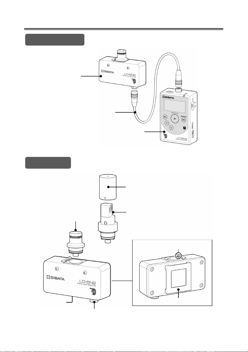
Product Contents
Check the package for the following items before using the product.
Detector unit ······················· 1
Control unit ························· 1
Connector cable··················· 1
AC adapter ························· 1
Clip ··································· 3
USB cable (A-miniB Type) ···············1
Soft case (for holding the control unit)····1
Warranty ·································1
Combination standard scattering plate and zero filter (with filter ×1*, protective
cap ×1) ························································································1
* The filter is attached to the combination standard scattering plate and zero filter.
Operation manuals for main unit, communication software (Japanese,
English)················································································1 each
Quick reference manual (Japanese, English) ······································1
Manufacture's Inspection Result·······················································1
Communication software for the LD-6N/6N2 (CD-ROM) ························1
Check the contents of the package before use. If any parts are broken or missing, contact the distributor
where you purchased the product.
Safety Precautions
The precautionary information in this operation manual is provided to ensure the
safe use of the product and to prevent property damage and injury to you and other
people. It is all important for ensuring safety, so be sure to read it thoroughly before
using the product and observe it during use.
Users (Important)
This product should only be operated by trained and experienced operators that
understand the specialized technology and dangers involved. Untrained or
currently being trained operators should only operate the product under close
supervision by a person that is already trained or has sufficient specialized
experience. This operation manual is written assuming the product will be operated
by a person that understands the risks of operating the product.