ENGLISH
Luminescence sensor
with bar graph and Teach-in
Operating Instructions
Safety notes
>Read the operating instructions before starting operation.
>Connection, assembly, and settings only by competent technicians.
>Protect the device against moisture and soiling when operating.
>No safety component in accordance with EU machine guidelines.
Risk group 1
WARNING: UV-light emitted from this product.
Do not stare at operating lamp.
Correct use
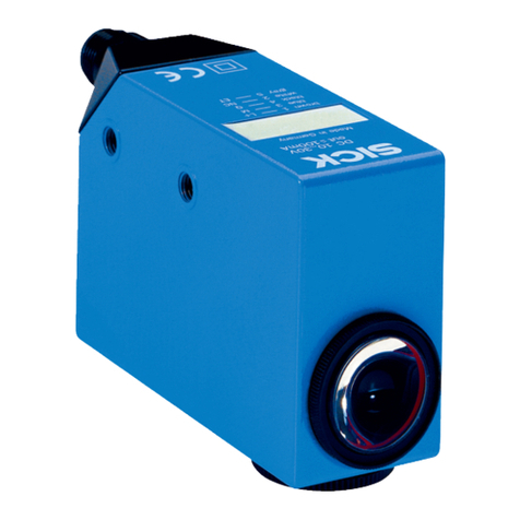
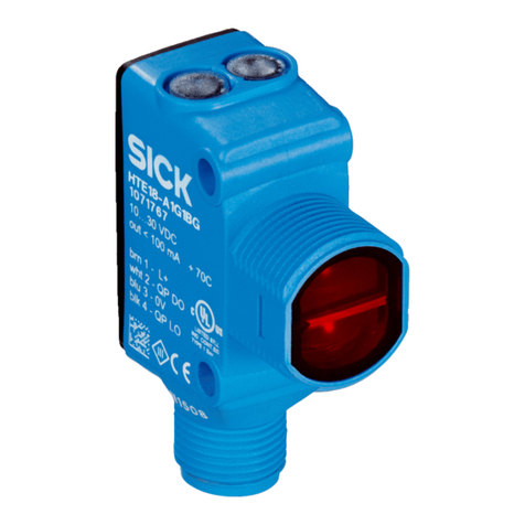
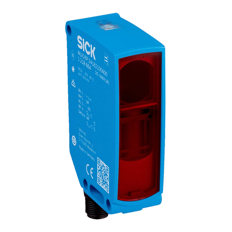
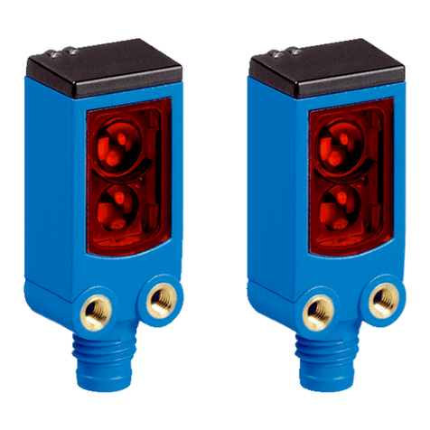
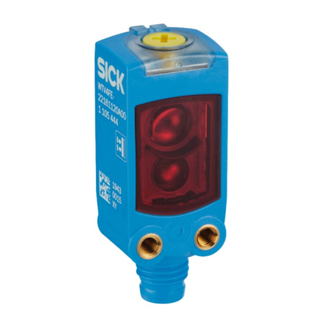
The luminescence sensor LUT9 is an optoelectronic sensor and is used for
optical, non-contact detection of uorescent test objects.
Starting operation
1 Equipment plug horizontally (H) and vertically (V) adjustable.
Connect and secure cable receptacle tension-free. The following apply
for connection in B: brn = brown, blk = black, blu = blu, wht = white,
gra = grey. Outputs: QPNP , QNPN or QA= analog output or
C/ Q = IO link.
Connect the sensor according to the Bconnection chart.
Mount sensor with mounting holes to a suitable xture and align it.
Pay attention to sensing range for this (see the technical data at the
end of these operating instructions and the chart, x = sensing range,
y = relative sensitivity, SW = switching threshold).
Align the horizontal and vertical movements of the test object using
correspondingly long markings.
Connect sensor to operating voltage (see nameplate).
The rst LED of the bar chart lights up.
Manufacturer’s setting: max. senstitivity, bright switchover.
2 Teach-in function:
Set selector knob to “TEACH”. Set bright and dark switchover via
Teach-in sequence. The yellow switch-output diode lights up when a
luminescent test object is detected.
2a First Teach-in operation:
Move luminescent mark or background into the light spot. Press the
Teach-in button. The transmitting light, the bar graph and the switch-
output diode ash slowly.
2b Second Teach-in operation:
Move luminescent mark or background into the light spot. Press the
Teach-in button. The bar graph glows continuously. If the transmitting
light and the switch-output diode ash, the dierence in luminescence
between mark and background was too low.
Bar graph:
Quality of Teach-in. The more LEDs light up, the better the Teach-in
operation. If the sensor is manually adjusted, no prediction of detec-
tion reliability is possible.
2c 1 LED lights up:
Unreliable teach-in. Stabilisation of operation: observe quality of
luminescence and sensing distance. Readjust or clean sensor or carry
out ne adjustment manually.
2d 2–4 LEDs light up:
Teach-in sucient, sucient luminescence or dierence present.
2e > 4 LEDs light up:
Reliable teach-in
3 Manualneadjustment,increaseordecreasesensitivity:
Turn selector knob to “+” or “–” and press Teach-in button.
The bar chart indicates sensitivity.
To trigger switching operation, output Q changes status if the neces-
sary intensity of luminescence is too high or too low. 2 x press is
equivalent to shifting one segment. The maximum degree of sensitivity
is achieved at 10 sec. Lock the Teach-in button with “RUN” to prevent
it being pressed accidentally. The bar graph indicates the intensity of
luminescence.
4 Setevaluationmode:
Set selector knob to “MODE” and press Teach-in button.
HR = high-resolution mode for low intensity of luminescence and long
response time.
S = standard mode for standard applications.
HS = high-speed mode for high intensity of luminescence and short
response time.
The luminescence intensity is displayed in evaluation mode.
Selector switches one position forward for each press of the button.
The last setting is saved.
5 Settingdelayinswitch-o:
Turn selector knob to “TIMER” and press Teach-in button. The bar
graph indicates the time-step set. Selector switches one position
forward for each press of the button. The last setting is saved.
Lens replacement:
The screwed-in lens can be replaced by another lens.
Sensing distances: 10 /20 /50/90 mm.
6 Reset:
Set selector knob to “MODE” and press Teach-in button > 5 sec.
Maintenance
SICK sensors are maintenance-free.
We recommend doing the following regularly:
- clean the external lens surfaces
- check the screw connections and plug-in connections.
No modications may be made to devices.
DEUTSCH
Lumineszenzsensor
mit Balkenanzeige und Teach-in
Betriebsanleitung
Sicherheitshinweise
>Vor der Inbetriebnahme die Betriebsanleitung lesen.
>Anschluss, Montage und Einstellung nur durch Fachpersonal.
>Gerät bei Inbetriebnahme vor Feuchte und Verunreinigung schützen.
>Kein Sicherheitsbauteil gemäß EU-Maschinenrichtlinie.
More representatives and agencies at www.sick.com ∙ Subject to change
without notice ∙ The specied product features and technical data do not
represent any guarantee.
Weitere Niederlassungen nden Sie unter www.sick.com ∙ Irrtümer
und Änderungen vorbehalten ∙ Angegebene Produkteigenschaften und
technische Daten stellen keine Garantieerklärung dar.
Plus de représentations et d’agences à l’adresse www.sick.com ∙ Sujet à
modication sans préavis ∙ Les caractéristiques de produit et techniques
indiquées ne constituent pas de déclaration de garantie.
Para mais representantes e agências, consulte www.sick.com ∙ Alterações
poderão ser feitas sem prévio aviso ∙ As características do produto e os
dados técnicos apresentados não constituem declaração de garantia.
Altri rappresentanti ed agenzie si trovano su www.sick.com ∙ Contenuti
soggetti a modiche senza preavviso ∙ Le caratteristiche del prodotto e i dati
tecnici non rappresentano una dichiarazione di garanzia.
Más representantes y agencias en www.sick.com ∙ Sujeto a cambio sin
previo aviso ∙ Las características y los datos técnicos especicados no
constituyen ninguna declaración de garantía.
欲了解更多代表机构和代理商信息,请登录 www.sick.com ∙
如有更改 , 不另行通知 ∙ 对所给出的产品特性和技术参数
的正确性不予保证。
その他の営業所は www.sick.com よりご覧ください ∙ 予告なし
に変更されることがあります ∙ 記載されている製品機能およ
び技術データは保証を明示するものではありません。
LUT9
-------------------------------------------------------- 8013227.1AY6 0221 COMAT -----------------------------------------------------
Q
– +
TEACH
RUN
–
+
MODETIMER
Q
A
1
2
5
3
4
LUT9U- _ 0 _ _ _
LUT9B- _ 0 _ _ _
LUT9U- _ 1 _ _ _
LUT9B- _ 1 _ _ _
LUT9U- _ 2 _ _ _
LUT9B- _ 2 _ _ _
2c
Q
–+
TEACH
RUN
–
+
(max. 10 s)
MODETIMER
„+“
„–“
Q
–+
TEACH
RUN
–
+
HR
S
HS
MODETIMER
1 x
2 x
3 x
S = Default
Q
–+
TEACH
RUN
–
+
0 ms
10 ms
20 ms
MODETIMER
1 x
2 x
3 x
0 ms = Default
Q
– +
TEACH
RUN
–
+
MODETIMER
Q
(slow)
(slow)
(slow)
Q
– +
TEACH
RUN
–
+
MODETIMER
Q
(fast)
(fast)
Q
2b
2a
BLUT9U-1 _ _ _ _
LUT9B-1 _ _ _ _ LUT9U-P _ _ _ _
LUT9U-N _ _ _ _
50
(1.97)
100
(3.94)
150
(5.91)
200
(7.87)
250
(0.83)
30.4
(1.20)
28
(1.10)
13
(0.51)
52
(2.05)
80
(3.15)
17
(0.67)
3
(0.12) 40
(1.57)
53
(2.09)
2d
2e
LUT9 U-11106 U-11206
U-12206
U-_120L
U-113_6
U-12306
B-12336
U-_130L
U-11406 U-11606
B-11626
Sensing range TW Tastweite TW Distance de détection TW Raio de exploração TW Distanza di ricezione TW Rango de exploración TW 探测距离 TW スキャニング範囲 TW Область сканирования (TW) 10 mm 1) 20 mm 1) 50 mm 1) 90 mm 1) 150 mm 1)
Light spot dimension Lichtfleckabmessung Dimension de la tache lumineuse Diâmetro do ponto de luz Diametro punto luminoso Dimensiones del punto de luz 光点直径 スポット径 Размер светового пятна 2 x 6 mm 3 x 9 mm 5 x 15 mm 12 x 12 mm 5 x 12 mm
Supply voltage VSVersorgungsspannung UVTension d’alimentation UVTensão de força UVTensione di alimentazione UVTensión de alimentación UV电源电压 UV供給電圧 UVНапряжение питания UVDC 12 ...30 V 2)
Current consumption Stromaufnahme Consommation de courant Consumo de corrente Corrente assorbita Consumo de corriente 电流消耗 供給電圧 Потребление тока < 100 mA 3)
Output current Imax. Ausgangsstrom Imax. Courant de sortie Imax. Corrente de saída Imax. Corrente di uscita max. Imax. Corriente de salida Imax. 输出电流 Imax. 最大出力電流 Imax. Выходной ток Imax. 100 mA
Signal sequence Signalfolge Fréquence Sequência de sinais Sequenza signali Secuencia de señales 信号流 信号伝達時間 Последовательность сигналов 500/s 2.500/s 6.500/ s 4)
Response time Ansprechzeit Temps de réponse Tempo de reação Tempo di risposta Tiempo de reacción 触发时间 応答時間 Время отклика 1.000 µs/200 µs/75 µs
Switching output Schaltausgang Sortie logique Saída de circuito Uscita di commutazione Salida de conmutación 开关输出端 スイッチング出力 Переключающий выход PNP High = UV ≤ 2V / Low ca. 0 V 5)
NPN High = ca. UV/Low < 2 V
Analog output QAAnalogausgang QASortie analogique QASaída analógica QAUscita analogica QASalida analógica QA模拟输出端QAアナログ出力 QAАналоговый выход QA0 … 12.5 mA 5) 6)
Protection class Schutzklasse Classe de protection Classe de proteção Classe di protezione Clase de protección 保护级别 保護クラス7) Класс защиты 7)
Enclosure rating (IEC 60529) Schutzart (IEC 60529) Type de protection (IEC 60529) Tipo de proteção (IEC 60529) Tipo di protezione (IEC 60529) Categoría de protección (IEC 60529) 保护种类(IEC60529) 保護等級(IEC60529) Степень защиты (IEC 60529) IP 67
Ambient operating temperature Betriebsumgebungstemperatur Température ambiante Temperatura ambiente de operação Temperatura ambiente circostante Temperatura ambiente de servicio 工作环境-温度 動作周囲温度 Диапазон рабочих температур –10 … +55 °C
1) From front edge of lens
2) Limits.
Residual ripple max. 5 VPP.
VSconnections reverse polarity protected.
Operation in short-circuit protected network
max. 8 A
3) Without load
4) Sensing ratio 1:1
5) Short-circuit protected
6) Reliable switching ≥ 2.5 mA
Rated load resistance RL = 500 W
7) Reference voltage 50 V DC
1) Ab Vorderkante Objektiv
2) Grenzwerte.
Restwelligkeit max. 5 VSS
UV-Anschlüsse verpolsicher.
Betrieb in kurzschlussgeschütztem Netz
max. 8 A
3) Ohne Last
4) Tastverhältnis 1:1
5) Kurzschlussgeschützt
6) Sicheres Schalten ≥ 2,5 mA
Nennlastwiderstand RL = 500 W
7) Bemessungsspannung DC 50 V
1) Depuis le bord avant de l’objectif
2) Valeurs limites
Ondulation résiduelle max. 5 VSS.
Raccordements UVprotégés contre les inversions
de polarité. Fonctionnement sous secteur protégé
contre les courts-circuits à 8 A max.
3) Sans charge
4) Rapport de détection 1 : 1
5) Protégé contre les courts-circuits
6) Commutation sûre ≥ 2,5 mA
Résistance ballast nominale RL = 500 W
7) Tension de calcul DC 50 V
1) A partir da borda da frente da objetiva
2) Valores limite.
Ondulação residual max. 5 VSS.
Conexões UVprotegidas contra inversão de polos.
Operação em rede com proteção contra curto-
circuito max. 8 A
3) Sem carga
4) Relação de deteç ão 1:1
5) Protegido contra curto-circuito
6) Comutação segura ≥ 2,5 mA
Resistência de carga nominal RL = 500 W
7) Tensão de dimensionamento DC 50 V
1) Dal bordo d’attacco dell’obiettivo
2) Valori limite.
Ondulazione residua max. 5 VSS.
UV-collegamenti con protezione contro inversione di poli.
Funzionamento in una rete protetta contro corto circuiti
massimo fino ad 8 A
3) Senza carico
4) Rapporto impulso-pausa 1:1
5) Protetto contro corto circuiti
6) Cambio sicuro ≥ 2,5 mA
Resistenza di carico nom. RL = 500 W
7) Tensione di taratura DC 50 V
1) A partir del borde delantero del objetivo
2) Límite.
De ondulación residual max. 5 VSS.
Conexiones UVprotegidas contra inversión de polos.
Funcionamiento en red protegida contra cortocircuitos max. 8 A
3) Sin carga
4) Relación de exploración 1:1
5) Protección contra cortocircuito
6) Conmutación segura ≥ 2,5 mA
Resistencia de la carga nominal RL = 500 W
7) Tensión de dimensionamiento DC 50 V
1) 自镜头前沿
2) 极限值剩。
余波纹度 max. 5 VSS。
UV-接头防反接。
在有短路保险的电网
工作电流最大为 8A
3) 时无负载
4) 探测比 1:1
5) 具有短路保险
6) 安全开关 ≥ 2,5mA
额定负载电阻 RL = 500W
7) 限定电压 DC 50 V
1) 対象物の前端から
2) 残留リ。
ップルの限界値、最大 5 VSS。
UV接続、逆極保護。
短絡保護された回路、8A 以下で使用
3) 負荷なし
4) 検出比 1:1
5) 短絡防止
6) 安全なスイッチング ≥ 2.5mA
負荷抵抗 RI=500Ω
7) 基準電圧 50 V DC
1) От передней кромки объектива
2) Предельные значения.
остаточной пульсации макс. 5 VSS Разъемы для
напряжения питания с защитой от перепутывания.
Эксплуатация в защищенных от короткого замыкания
сетях с силой тока не более 8A.
3) Без нагрузки
4) Коэффициент усреднения 1:1
5) С защитой от короткого замыкания
6) Безопасное переключение ≥ 2,5 мА
Номинальное сопротивление нагрузки RL = 500 W
7) Расчетное напряжение DC 50 V
Risikogruppe 1
WARNUNG: UV-Strahlung emittiert durch dieses Produkt.
Bei Betrieb nicht in die Lampe blicken.
Bestimmungsgemäße Verwendung
Der Lumineszenzsensor LUT9 ist ein optoelektronischer Sensor und wird
zum optischen, berührungslosen Erfassen von uoreszierenden Prüfobjek-
ten eingesetzt.
Inbetriebnahme
1 Gerätestecker nach horizontal (H) und vertikal (V) schwenkbar.
Leitungsdose spannungsfrei aufstecken und festschrauben. Für
Anschluss in Bgilt: brn = braun, blk = schwarz, blu = blau, wht = weiß,
gra = grau.
Ausgänge: QPNP ,QNPN , QA= Analogausgang oder C/ Q = IO-Link.
Sensor laut Anschlussschema Banschließen.
Sensor mit Befestigungsbohrungen an geeignetem Halter montieren
und grob ausrichten. Dabei Tastweite beachten (s. technische Daten
am Ende dieser Betriebsanleitung und siehe Diagramm, x = Tastweite,
y = relative Empndlichkeit, SW = Schaltschwelle).
Seiten- und Höhenbewegungen des Prüfobjektes durch entsprechend
lange Markierungen ausgleichen.
Sensor an Betriebsspannung legen (s. Typenaufdruck), die erste LED
der Balkenanzeige leuchtet.
Auslieferungszustand: max. Empndlichkeit, hellschaltend.
2 Teach-in:
Drehwahlschalter auf „TEACH“.
Hell- und Dunkelschaltung über die Reihenfolge des Teach-in festle-
gen. Die gelbe Schaltausgangsdiode leuchtet bei Erkennung eines
lumineszierenden Prüfobjekts.
2a Erster Teach-in-Vorgang:
Lumineszierende Marke oder Untergrund in den Lichteck bringen,
Teach-in-Taste drücken. Das Sendelicht, die Balkenanzeige und die
Schaltausgangsdiode blinken langsam.
2b ZweiterTeach-in-Vorgang:
Untergrund oder lumineszierende Marke in den Lichteck bringen,
Teach-in-Taste drücken. Die Balkenanzeige leuchtet kontinuierlich.
Blinkt das Sendelicht und die Schaltausgangsdiode, war der Lu-
mineszenzunterschied Marke/Untergrund zu gering.
Balkenanzeige:
Qualität des Teach-in. Je mehr LEDs leuchten, desto besser ist der
Teach-in.
Wird der Sensor manuell nachjustiert, ist keine Aussage über Detek-
tionssicherheit möglich.
2c 1 LED leuchtet:
Kein zuverlässiger Teach. Stabilisieren des Betriebs:
Lumineszenzqualität und Tastweite beachten. Sensor neu justieren
bzw. reinigen oder manuelle Feineinstellung durchführen.
2d 2–4 LEDs leuchten:
Teach ausreichend, ausreichende Lumineszenz bzw. Unterschied
vorhanden.
2e > 4 LEDs leuchten:
Zuverlässiger Teach
3 ManuelleFeineinstellung,Empndlichkeitanheben/absenken:
Drehwahlschalter auf „+“ oder „–“ und Teach-in-Taste drücken: Balke-
nanzeige zeigt Empndlichkeit an.
Ausgang Q wechselt Zustand bei Über- bzw. Unterschreitung der
notwendigen Lumineszenzintensität, um Schaltvorgang auszulösen.
2 x drücken entspricht Verschiebung eines Segments. Max.
Empndlichkeitsstufe bei 10 s erreicht. Die Teach-in-Taste gegen
unbeabsichtiges Betätigen mit „RUN“ sperren. Balkenanzeige zeigt die
Lumineszenzintensität an.
4 EinstellungAuswerte-Modus:
Drehwahlschalter auf „MODE“ und Teach-in-Taste drücken:
HR = High-Resolution-Mode für geringe Lumineszenzintensität und
lange Ansprechzeit.
S = Standard-Mode für Standardanwendungen.
HS = High-Speed-Mode für hohe Lumineszenzintensität und kurze
Ansprechzeit.
Im Auswertemodus wird die Lumineszenzintensität angezeigt.
Auswahl läuft pro Tastendruck eine Position weiter. Letzte Einstellung
wird gespeichert.
5 EinstellungAusschaltverzögerung:
Drehwahlschalter auf „TIMER“ und Teach-in-Taste drücken: Balkenan-
zeige zeigt eingestellte Zeitstufe an.
Auswahl läuft pro Tastendruck eine Position weiter. Letzte Einstellung
wird gespeichert.
Objektivwechsel:
Das eingeschraubte Objektiv kann gegen andere Ob jektive ausgetau-
scht werden. Tastweiten: 10 / 20/ 50 / 90 mm
6 Reset:
Drehwahlschalter auf „MODE“ und Teach-in-Taste > 5 s drücken.
Wartung
SICK-Sensoren sind wartungsfrei.
Wir empfehlen, in regelmäßigen Abständen
– die optischen Grenzächen zu reinigen,
– Verschraubungen und Steckverbindungen zu überprüfen.
Veränderungen an Geräten dürfen nicht vorgenommen werden.
28
(1.10)
