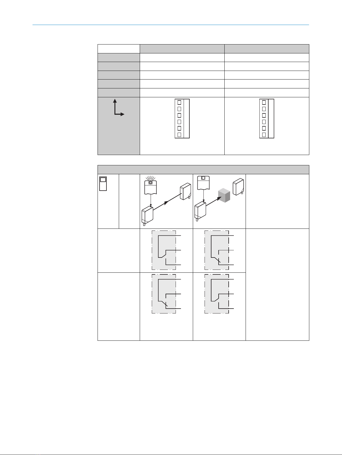
3Switch: light (L) / dark
(D)
4Switch: NPN / PNP
5Potentiometer: adjust‐
ment of time delay t2
6Potentiometer: adjust‐
ment of time delay t1
7Potentiometer: adjust‐
ment of time stage
3Switch: light (L) / dark
(D)
4Switch: NPN / PNP
3Switch: light (L) / dark
(D)
4Potentiometer: adjust‐
ment of time delay t2
5Potentiometer: adjust‐
ment of time delay t1
6Potentiometer: adjust‐
ment of time stage
3Switch: light (L) / dark
(D)
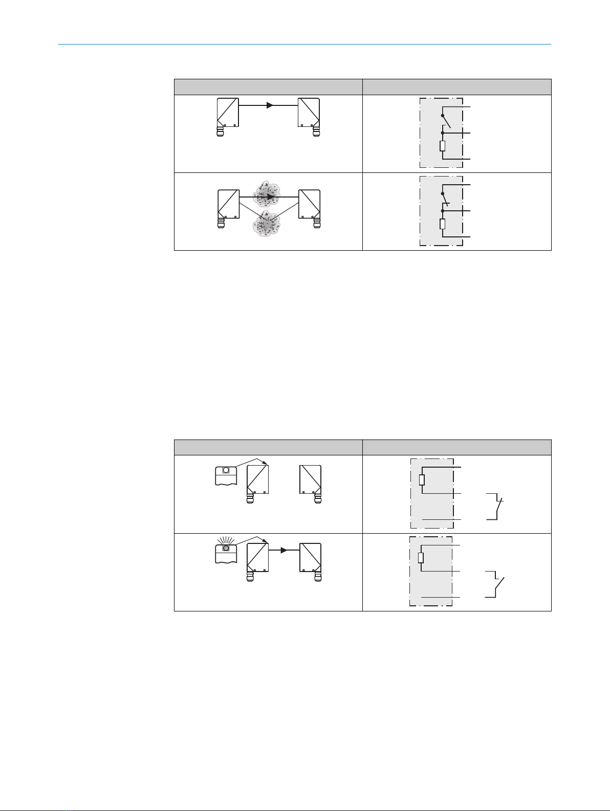
5 Mounting
Mount sensors (sender and receiver) using suitable mounting brackets (see the SICK
range of accessories). Align the sender and receiver with each other.
NOTE
Swap the sender and receiver arrangement at every second through-beam photoelec‐
tric sensor and ensure that there is sufficient distance between the through-beam pho‐
toelectric sensors.
Receiver (WE)
Receiver (WE)
Sender (WS)
Sender (WS)
Sender (WS)
Receiver (WE)
Figure 1: Arrangement of several through-beam photoelectric sensors
Note the sensor’s maximum permissible tightening torque of 2 Nm.
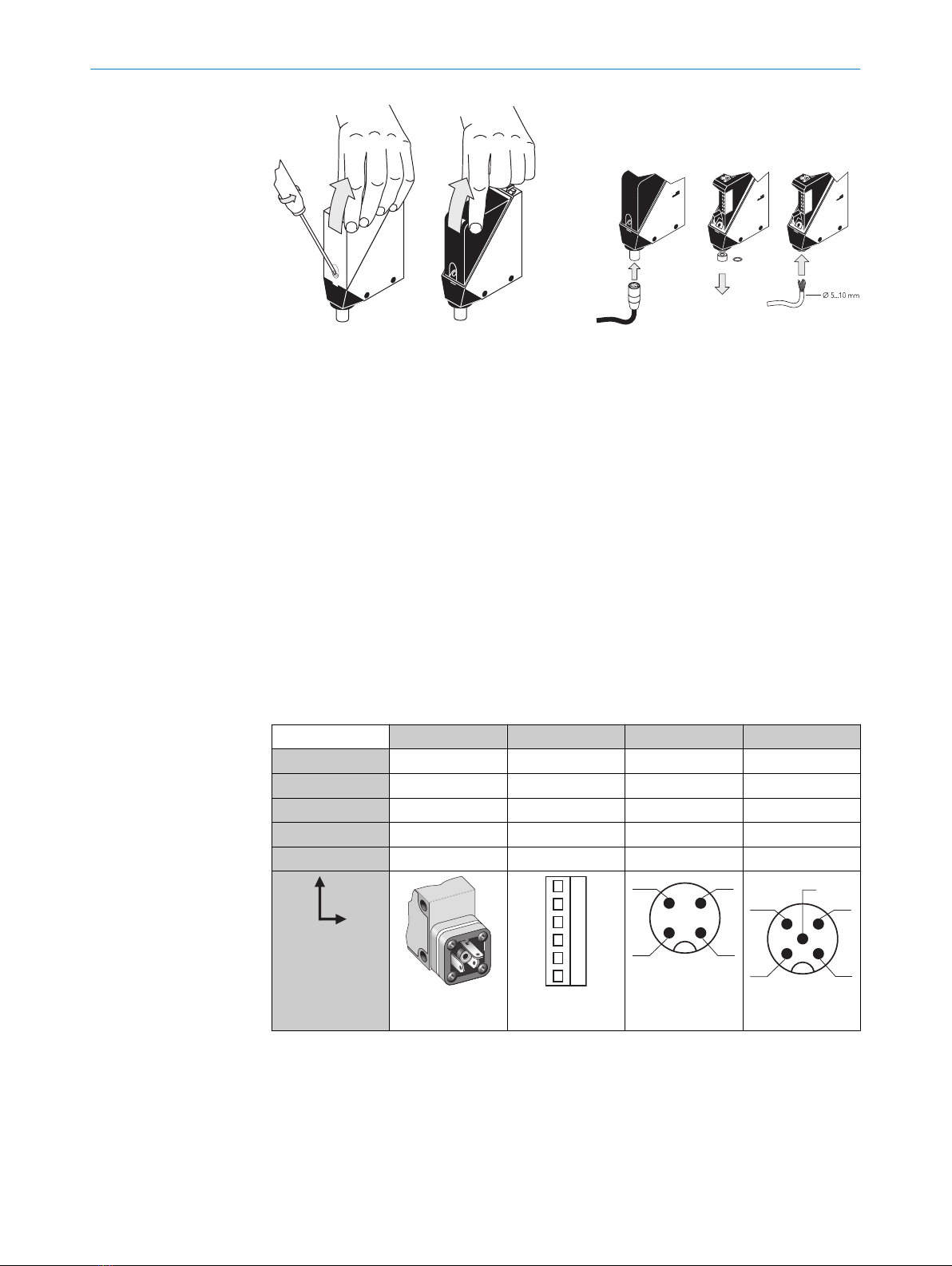
6 Electrical installation
The sensors must be connected in a voltage-free state. The following information must
be observed, depending on the connection type:
– Plug connection: note pin assignment: when the cover is open, the male connector
can be swiveled horizontally and vertically.
– Terminal connection: note the permissible cable diameter of 5 to 10 mm. When
the cover is open, the M16 fitting can be swiveled horizontally and vertically.
Unscrew the M16 fitting and remove sealing plug. Lead voltage-free supply cable
through and connect sensor in accordance with table 2 and table 5. Retighten
M16 fitting with seal so that the IP enclosure rating of the device is ensured.
5 MOUNTING
68009200.11O1 | SICK
Subject to change without notice