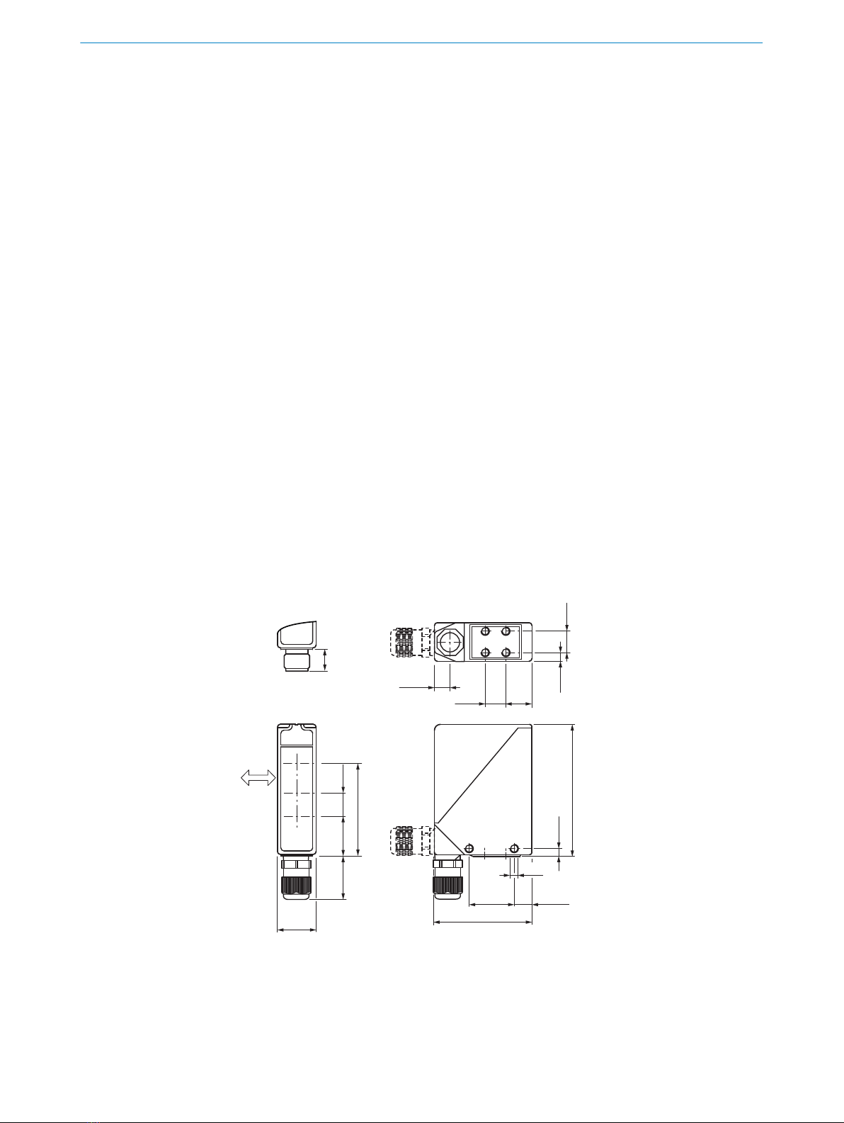
6Center of optical axis, receiver (far range)
7M5 threaded mounting hole, 6 mm deep
8M5 threaded mounting hole, through-hole
9M16 screw fixing and plug rotatable by 90°
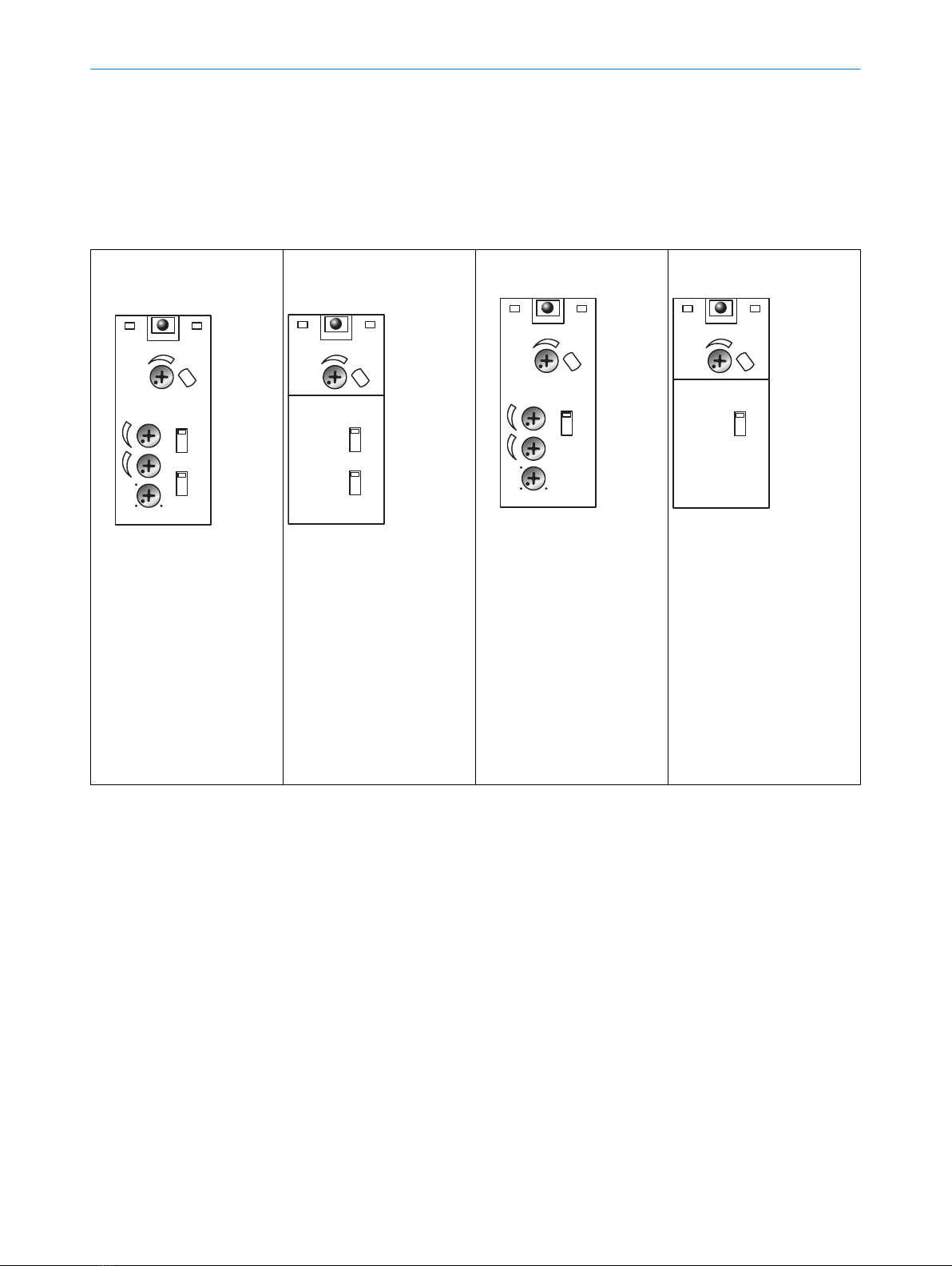
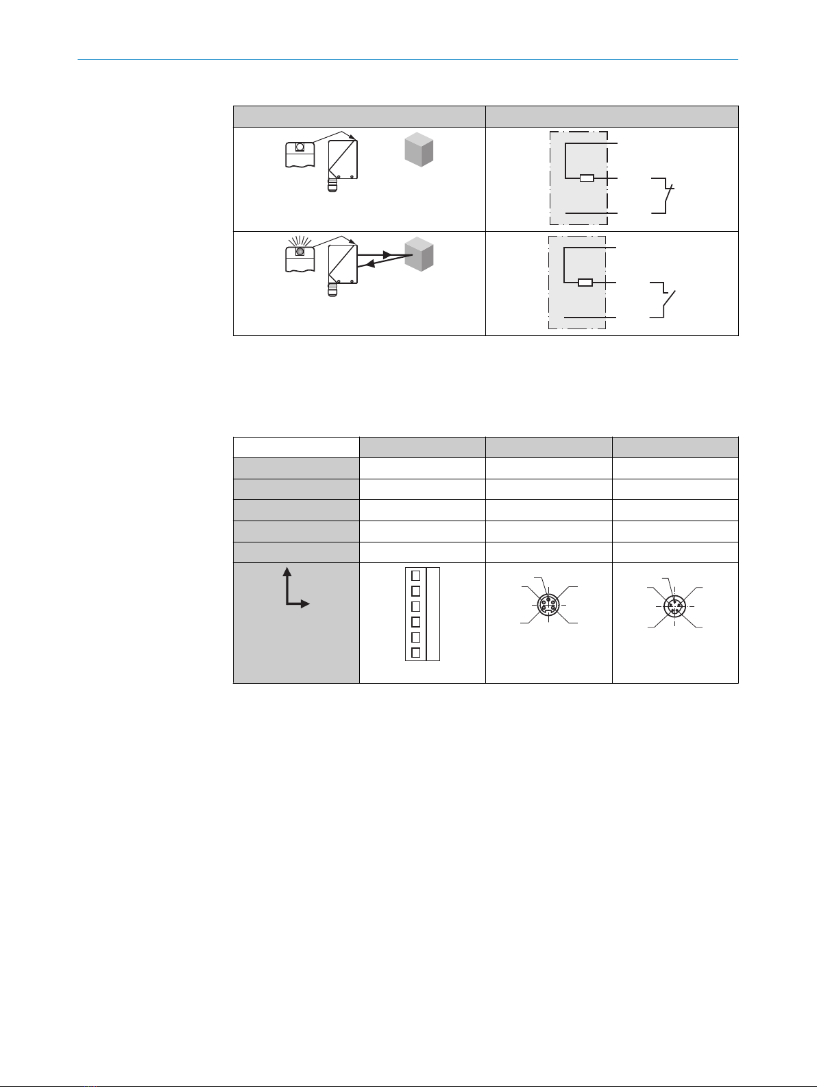
Table 1: Display and operating elements
WT24-2Bx2x, -2Vx2x, -2Bx5x,
-2Vx5x
t2
t2
t1
t1
t1+ t2
t0
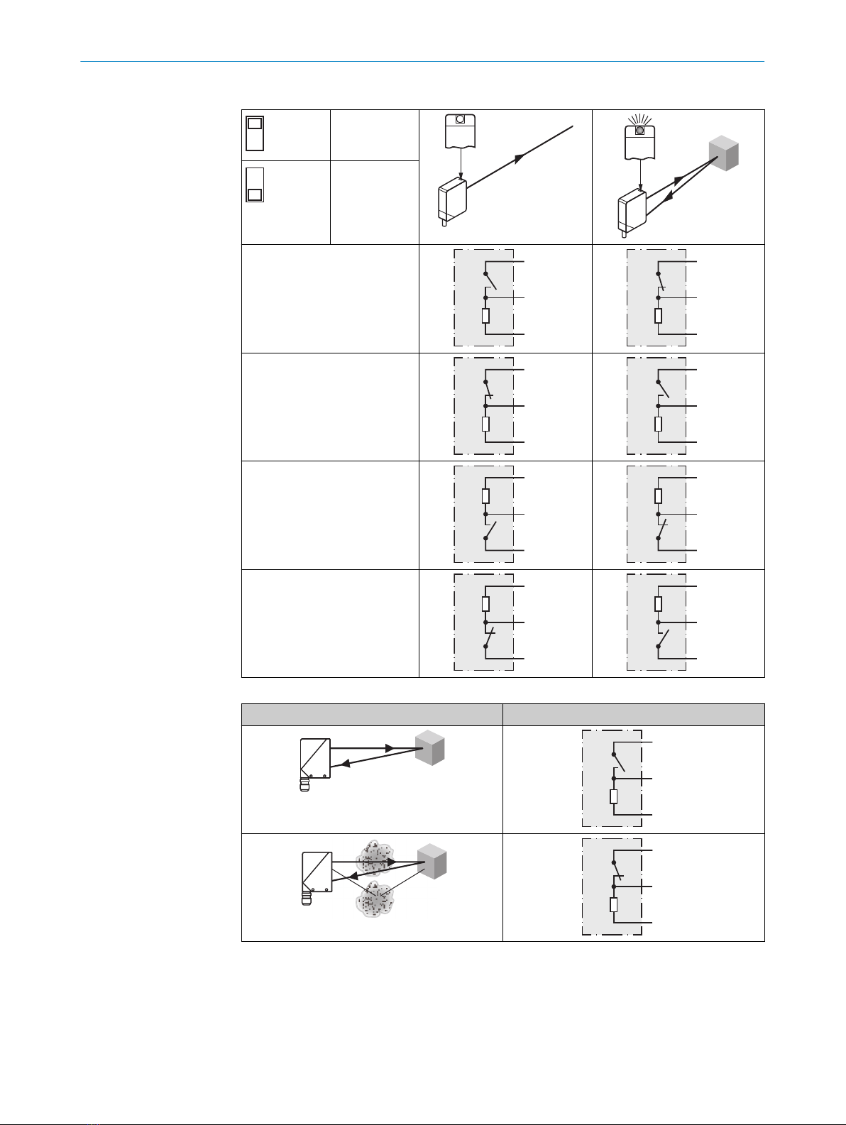
PNP
NPN
D
H
1
2
3
6
4
5
7
1.0
1Yellow LED indicator
2Potentiometer: adjust‐
ing the sensing range
3Switch: light (L) / dark
(D)
4Switch: NPN / PNP
5Potentiometer: adjust‐
ment of time delay t2
6Potentiometer: adjust‐
ment of time delay t1
7Potentiometer: adjust‐
ment of time stage
WT24-2Bx1x, -2Vx1x, -2Bx4x,
-2Vx4x
1Yellow LED indicator
2Potentiometer: adjust‐
ing the sensing range
3Switch: light (L) / dark
(D)
4Switch: NPN / PNP
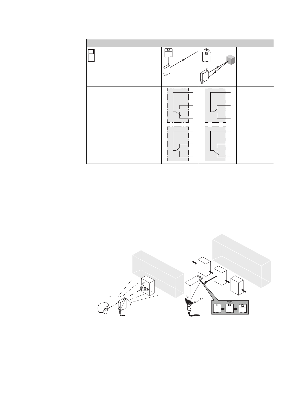
WT24-2Rx2x, -2Rx5x
t2
t2
t1
t1
t1+ t2
t0
D
H
1.0
1
2
3
5
4
6
1Yellow LED indicator
2Potentiometer: adjust‐
ing the sensing range
3Switch: light (L) / dark
(D)
4Potentiometer: adjust‐
ment of time delay t2
5Potentiometer: adjust‐
ment of time delay t1
6Potentiometer: adjust‐
ment of time stage
WT24-2Rx1x, -2Rx4x
1Yellow LED indicator
2Potentiometer: adjust‐
ing the sensing range
3Switch: light (L) / dark
(D)
4 Mounting
Mount the sensor using a suitable mounting bracket (see the SICK range of accesso‐
ries).
Note the sensor's maximum permissible tightening torque of 2 Nm.
Note the preferred direction of the object relative to the sensor, cf. figure 1.
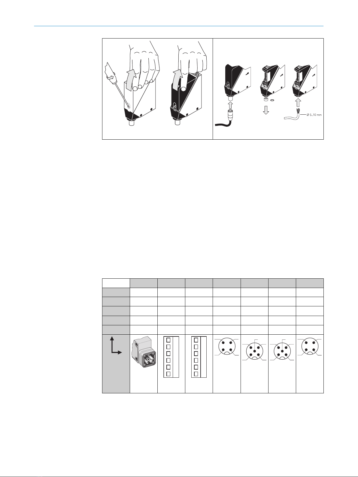
5 Electrical installation
The sensors must be connected in a voltage-free state (UV = 0 V). The following informa‐
tion must be observed, depending on the connection type:
– Plug connection: note pin assignment: when the lid is open, the male connector
can be swiveled horizontally and vertically.
– Terminal connection: Note the permissible cable diameter of 5 to 10 mm. When
the lid is open, the M16 connector can be swiveled horizontally and vertically.
Unscrew the M16 connector and remove sealing plug. Lead voltage-free supply
cable through and connect sensor in accordance with table 2 table 6. Retighten
M16 connector with seal so that the IP enclosure rating of the device is ensured.
3 OPERATING AND STATUS INDICATORS
68008784.Z474 | SICK
Subject to change without notice