SICK LiDAR Manual

TECHNICAL INFORMATION
LiDAR Localization Hardware Integration
LiDAR localization

Described product
LiDAR Localization Hardware Integration
Manufacturer
SICK AG
Erwin-Sick-Str. 1
79183 Waldkirch
Germany
Legal information
This work is protected by copyright. Any rights derived from the copyright shall be
reserved for SICK AG. Reproduction of this document or parts of this document is only
permissible within the limits of the legal determination of Copyright Law. Any modifica‐
tion, abridgment or translation of this document is prohibited without the express writ‐
ten permission of SICK AG.
The trademarks stated in this document are the property of their respective owner.
© SICK AG. All rights reserved.
Original document
This document is an original document of SICK AG.
2T E C H N I C A L I N F O R M A T I O N | LiDAR Localization Hardware Integration 8024819/2019-09-02 | SICK
Subject to change without notice

Contents
1 About this document........................................................................ 4
1.1 Purpose of this document........................................................................ 4
1.2 Scope......................................................................................................... 4
1.3 Target groups............................................................................................ 4
1.4 Symbols and document conventions...................................................... 4
2 Safety information............................................................................ 5
2.1 General safety notes................................................................................ 5
3 Supported hardware......................................................................... 6
3.1 2D LiDAR sensors..................................................................................... 6
3.2 Localization controllers............................................................................ 6
4 Device overview................................................................................. 8
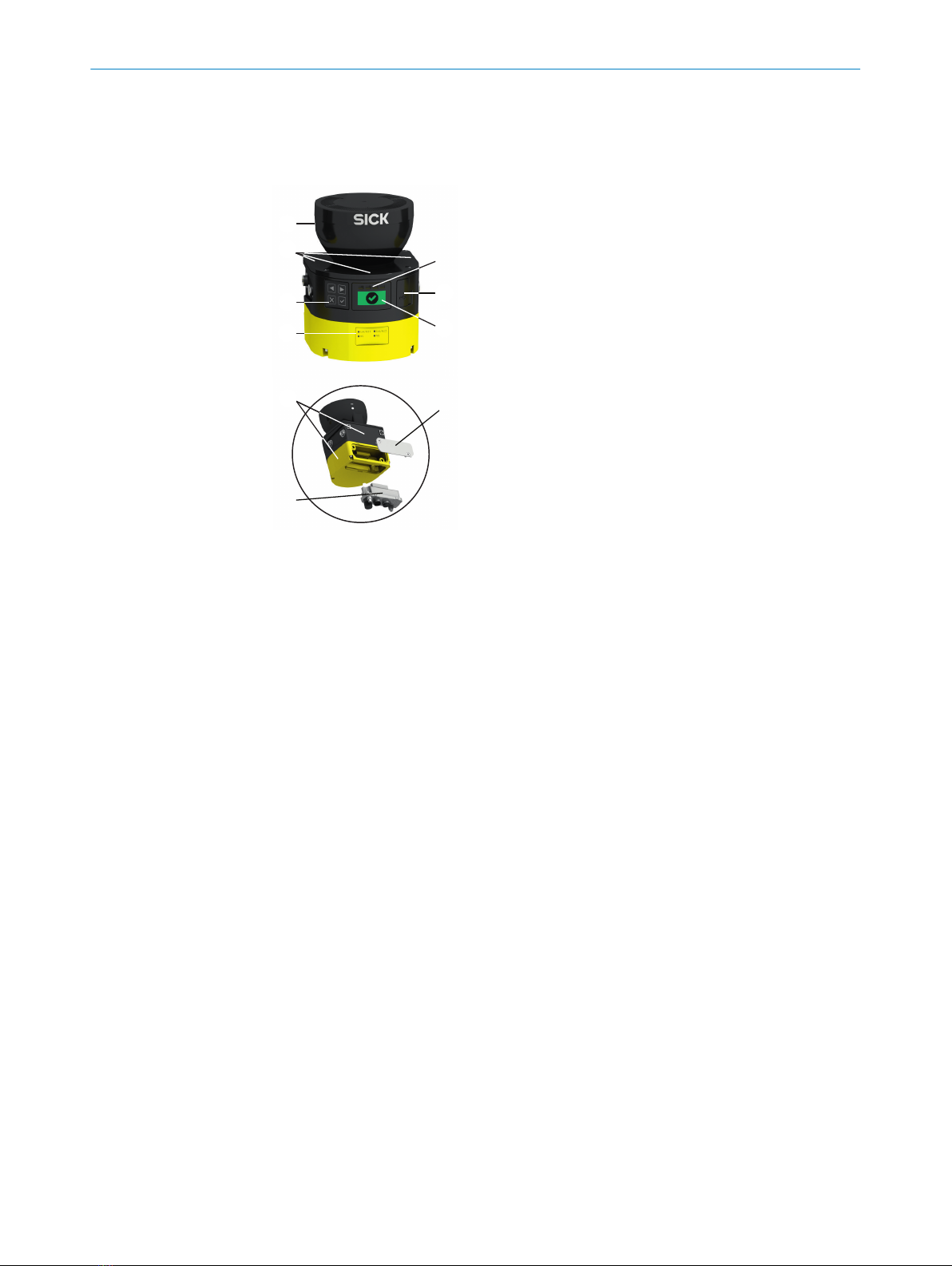
4.1 Device overview microScan3................................................................... 8
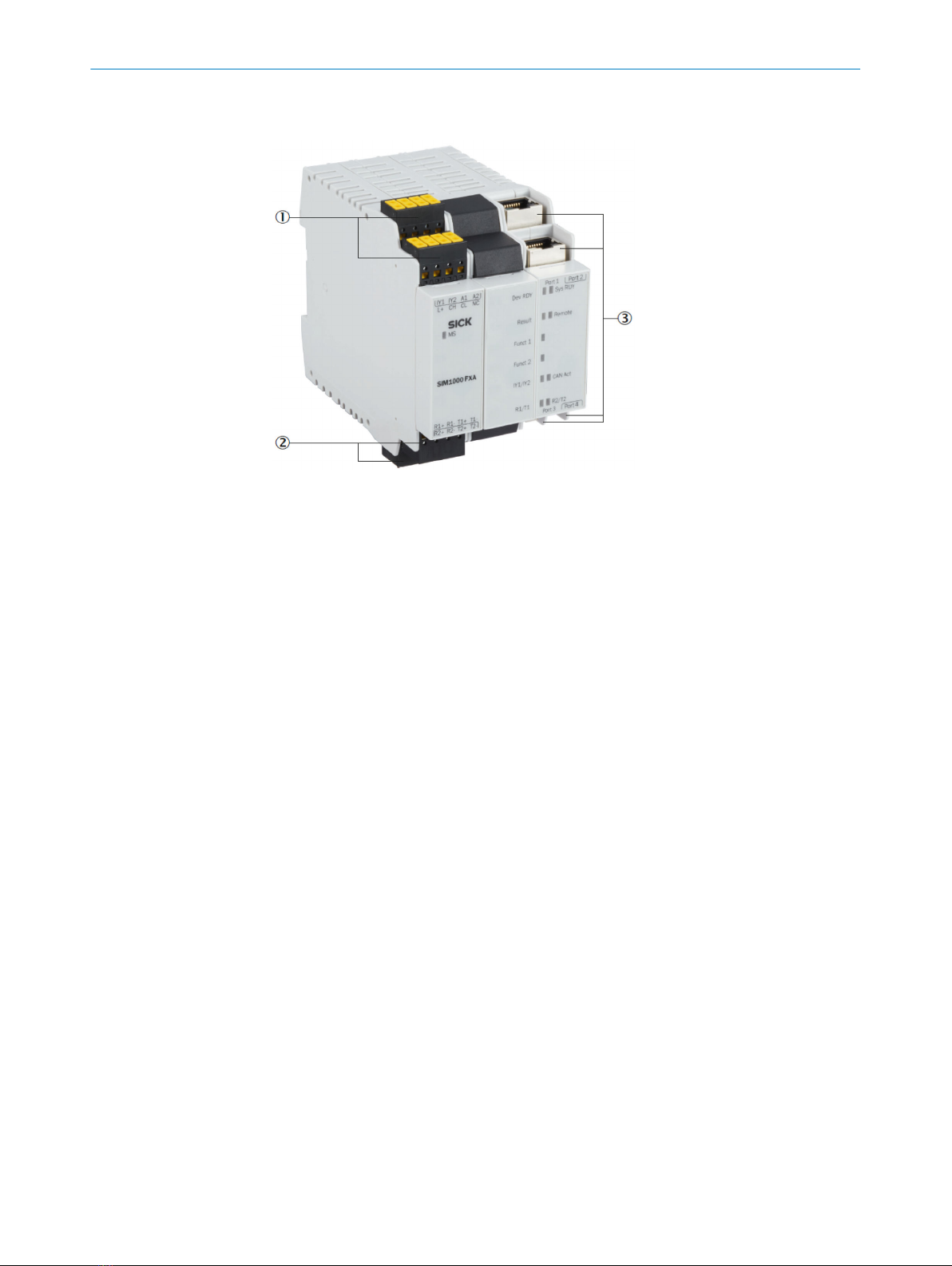
4.2 Device overview SIM1000 FXA................................................................ 9
5 Electrical installation........................................................................ 10
5.1 Important notes........................................................................................ 10
5.2 MicroScan3............................................................................................... 10
5.2.1 Electrical setup........................................................................ 10
5.3 SIM1000 FXA............................................................................................ 11
5.3.1 Preparations and overview...................................................... 12
5.3.2 Pin allocations of the connections......................................... 12
5.3.3 Network setup.......................................................................... 13
6 MicroScan3 configuration of the data output............................... 17
6.1 Important notes........................................................................................ 17
6.2 Overview.................................................................................................... 17
6.3 Activating and configuring data output................................................... 17
6.4 Single receiver of measurement data..................................................... 18
6.4.1 Configuring with the Safety Designer..................................... 18
6.5 Multiple receivers of measurement data via broadcast........................ 19
7 Operation............................................................................................ 21
7.1 Status LEDs SIM1000 FXA...................................................................... 21
8 List of figures..................................................................................... 23
9 List of tables....................................................................................... 24
CONTENTS
8024819/2019-09-02 | SICK T E C H N I C A L I N F O R M A T I O N | LiDAR Localization Hardware Integration 3
Subject to change without notice

1 About this document
1.1 Purpose of this document
This additional technical note describes the hardware integration and how to enable the
measurement data of the 2D LiDAR sensor.
The full operating instructions of the used 2D LiDAR sensor must be made available to
all people who work with the device.
1.2 Scope
This document is included with the following SICK part numbers (this document in all
available language versions):
•8024819
1.3 Target groups
This document is written for system specialists working in the field of hardware devel-
opment intending to integrate the LiDAR localization system in their application.
1.4 Symbols and document conventions
The following symbols and conventions are used in this document:
Safety notes and other notes
DANGER
Indicates a situation presenting imminent danger, which will lead to death or serious
injuries if not prevented.
WARNING
Indicates a situation presenting possible danger, which may lead to death or serious
injuries if not prevented.
CAUTION
Indicates a situation presenting possible danger, which may lead to moderate or minor
injuries if not prevented.
NOTICE
Indicates a situation presenting possible danger, which may lead to property damage if
not prevented.
NOTE
Indicates useful tips and recommendations.
Instructions to action
bThe arrow denotes instructions to action.
1. The sequence of instructions for action is numbered.
2. Follow the order in which the numbered instructions are given.
✓The check mark denotes the result of an instruction.
1 ABOUT THIS DOCUMENT
4T E C H N I C A L I N F O R M A T I O N | LiDAR Localization Hardware Integration 8024819/2019-09-02 | SICK
Subject to change without notice

2 Safety information
2.1 General safety notes
DANGER
Danger of using data output for safety function
Data output may only be used for general monitoring and control tasks.
bDo not use data output for safety-related applications.
DANGER
Danger of using CoLa2 for safety function
CoLa2 may only be used for general monitoring and control tasks.
bDo not use CoLa2 for safety-related applications.
SAFETY INFORMATION 2
8024819/2019-09-02 | SICK T E C H N I C A L I N F O R M A T I O N | LiDAR Localization Hardware Integration 5
Subject to change without notice

3 Supported hardware
3.1 2D LiDAR sensors
LiDAR-LOC is qualified for the SICK sensor family microScan3.
NOTICE
SICK does not guarantee that the system functions with other sensors.
Table 1: Supported sensor data
Supported sensor
data
2D LiDAR sensor
Supported device (pro‐
tective field range)
microScan3
4.0 m
microScan3
5.5 m
microScan3
9.0 m
Aperture angle 275°
Distance range 1.8 %: 4 m
100 %: 40 m
1.8 %: 5.5 m
100 %: 40 m
1.8 %: 9 m
100 %: 64 m
Scan cycle time 30 ms
40 ms
40 ms
50 ms
For additional information, consult the operation instructions of the corresponding sen‐
sor.
For high quality of the localization, we recommend to consider the following information
about the sensors.
microScan3
•Protective field range 9 m (64 m warning field range)
The sensors with 64 m measurement range are preferred over the ones with 40 m
measurement range. They can be used in both configurations, 50 ms and 40 ms
scan cycle time. Smaller scan cycle times allow potentially higher velocities, how‐
ever, are primarily dependent on your risk assessment.
•Protective field range 4 m and 5.5 m (40 m warning field range)
When using the sensors with 40 m measurement range, they can be used in both
configurations, 40 ms and 30 ms scan cycle time, with corresponding 0.39° and
0.51° resolution. A smaller scan cycle time allows potentially higher velocities. A
higher resolution allows the detection of smaller objects. However, the configura‐
tion is primarily dependent on your risk assessment.
Complementary information
You can find additional information of the microScan3 in the operating instructions:
•8020198 microScan3 EtherNet/IPTM
•8021217 microScan3 PROFINET
•8021911 microScan3 EFI-pro
3.2 Localization controllers
Localization controllers
LiDAR-LOC uses the SIM1000-FXA. For quick integration, some information is provided
in this document.
3 SUPPORTED HARDWARE
6T E C H N I C A L I N F O R M A T I O N | LiDAR Localization Hardware Integration 8024819/2019-09-02 | SICK
Subject to change without notice

NOTICE
By default, the localization controller is a programmable device. When using the local‐
ization controller with the application software LiDAR-LOC, the controller is converted
into an application device. This means that the device cannot be programmed any
longer; it is locked for any additional application and cannot be unlocked.
Complementary information
You can find additional information of the localization controller in the operating instruc‐
tions 8023299.
SUPPORTED HARDWARE 3
8024819/2019-09-02 | SICK T E C H N I C A L I N F O R M A T I O N | LiDAR Localization Hardware Integration 7
Subject to change without notice

4 Device overview
4.1 Device overview microScan3
Figure 1: microScan3 – overview
1Optics cover
2Display
3Keypad
4USB port
5Status LEDs
6Additional LEDs for ON state and OFF state
7Network LEDs
8Safety laser scanner without system plug
9System plug
ßCover plate
4 DEVICE OVERVIEW
8T E C H N I C A L I N F O R M A T I O N | LiDAR Localization Hardware Integration 8024819/2019-09-02 | SICK
Subject to change without notice

4.2 Device overview SIM1000 FXA
Figure 2: SIM1000 FXA – overview
1Connections for switching input/output, IO-Link, CAN, and voltage supply
2Serial connections
3Ethernet connections
DEVICE OVERVIEW 4
8024819/2019-09-02 | SICK T E C H N I C A L I N F O R M A T I O N | LiDAR Localization Hardware Integration 9
Subject to change without notice

5 Electrical installation
5.1 Important notes
Information on the requirements that must be met for safe integration of the localiza‐
tion controller and 2D LiDAR sensors into the control and electronics of the machine,
see the corresponding operating instructions.
DANGER
Hazard due to electrical voltage
Hazard due to unexpected starting of the machine
bMake sure that the machine is (and remains) disconnected from the power supply
during the electrical installation.
bMake sure that the dangerous state of the machine is (and remains) switched off.
bCarry out the electrical installation work in conformity with EN 60204-1.
bUse suitable power supply.
bCheck that all earthing points are connected with the same ground potential.
bConnect the shielding of all data lines (Ethernet, CAN, serial) directly to the func‐
tional earth (FE) at the control cabinet entry point.
5.2 MicroScan3
The electrical installation is described in detail in the operating instructions:
•8021911
The examples are given for microScan3 EFI-pro variant but are also applicable for Ether‐
Net/IP™ and PROFINET.
5.2.1 Electrical setup
Supply voltage and power consumption
Supply voltage:
•24 V DC (16.8 … 30 V DC) (SELV/PELV) according to IEC 60364441
•Must be able to bridge a brief power outage of 20 ms with a starting voltage of
≤ 3 A
The microScan3 consumes the following:
•Power consumption ≤ 11 W (typ. 7.2 W)
•Power consumption Standby typical 7 W
System plug and connections
Table 2: Position of the electrical connections
Safety laser scan‐
ners
Suitable system plug Plug connector
microScan3 – Ether‐
Net/IP™
XD1 XF1 XF2
MICSX-BANNZZZZ1 (part number:
2086102)
•XD1: voltage supply,
•XF1, XF2: 2 × Ethernet
for EtherNet/IP –
CIP Safety, data output,
configuration, and diag‐
nostics.
5 ELECTRICAL INSTALLATION
10 T E C H N I C A L I N F O R M A T I O N | LiDAR Localization Hardware Integration 8024819/2019-09-02 | SICK
Subject to change without notice

Voltage supply (XD1)
Voltage supply is supplied via a 4-pin, A-coding M12 male connector on the device side.
12
3 4
Figure 3: Pin assignment of the voltage supply (male connector, M12, 4-pin, A-coded)
Table 3: Pin assignment of the voltage supply
Pin Marking Function Wire color 1)
1 +24 V DC 24 V DC supply voltage Brown
2 NC Not connected White
3 0 V DC 0 V DC supply voltage Blue
4 FE Functional earth/shield Black
1) Applies to the connecting cables recommended as accessories.
Ethernet for EFI-pro, data output, configuration, and diagnostics (XF1, XF2)
On the device side, Ethernet and EFI-pro are connected via 4-pin, D-coding M12 female
connectors. There is a network switch in the safety laser scanner which connects the
two Ethernet female connectors. The two Ethernet female connectors therefore have
the same function. The pin assignment corresponds to EN 61918, Appendix H.
43
2 1
Figure 4: Ethernet pin assignment (female connector, M12, 4-pin, D-coding)
Table 4: Ethernet pin assignment
Pin Designation Function
1 TX+ Send data +
2 RX+ Receive data +
3 TX– Send data -
4 RX– Receive data -
Housing SH Shielding
5.3 SIM1000 FXA
The electrical installation is described in detail in the operating instructions:
•8023298
ELECTRICAL INSTALLATION 5
8024819/2019-09-02 | SICK T E C H N I C A L I N F O R M A T I O N | LiDAR Localization Hardware Integration 11
Subject to change without notice

5.3.1 Preparations and overview
Preparing the electrical installation
To carry out the electrical installation, you will need:
•Connection cables for the peripheral devices, including the corresponding data
sheets
•Voltage supply cable
•If customers assemble the cables: crimping tool, ferrules, soldering iron, and other
installation material
Overview of connections
1Terminal block 1 and 2
2Terminal block 3 and 4
3Ethernet connections
5.3.2 Pin allocations of the connections
Important information
NOTE
The SIM1000 FXA device is supplied with power from an external power supply unit via
the pins A1 and A2.
Pin allocations of the connections
Only the pins for supply voltage, ground, and input/outputs are used in the LiDAR local‐
ization applica-tion.
For the power supply of the SIM1000 FXA, connect the open ends of the power supply
cable to the pins of the terminal block 1.
When using the CoLa-A synchronization methods, connect the I/O port of the vehicle
controller with IY2 of the terminal block 2 of the SIM1000 FXA.
5 ELECTRICAL INSTALLATION
12 T E C H N I C A L I N F O R M A T I O N | LiDAR Localization Hardware Integration 8024819/2019-09-02 | SICK
Subject to change without notice

Figure 5: Terminal block 1 and 2
Table 5: Pin allocations of the connections
Designation Signal Function
IY2 Output 1 Synchronization I/O when using command LocRequestTime‐
stamp
A1 +24 V Supply voltage IN
A2 GND Ground
Switching output
•Max. output current: 100 mA
•Min. high output logic level: VCC – 3 V
•Max. low output logic level: 3 V
•Push/Pull, NPN, PNP configurable
5.3.3 Network setup
5.3.3.1 Preset Ethernet interfaces
NOTE
Preset IP addresses of the Ethernet interfaces:
•Port 1: 192.168.0.1 (e.g. connection to the service computer)
•Port 2: 192.168.1.1 (e.g. connection to the 2D LiDAR sensor)
•Port 3: 192.168.2.1 (e.g. connection to the vehicle controller)
•Port 4: 192.168.3.1
When expanding the GigE interfaces with one or more Ethernet switches, it is essential
to use only jumbo-frame compatible GigE switches. Switches limited to just 100 MB do
not support the data packet mode used by cameras and can cause transmission
errors.
Changing the IP addresses
The individual IP addresses can be changed using the SICK SOPAS ET PC tool. This is
described in detail in the “SIM Getting Started Guide”, which is available for download
from the SICK AppSpace area of the SICK Support Portal. This guide also includes fur‐
ther notes on how to connect SICK sensors and the SICK picoCam and midiCam cam‐
eras to the Ethernet interfaces.
5.3.3.2 Ethernet connections
Important information
NOTICE
Shielded Ethernet cables must be used. The shielding of the Ethernet cables must be
connected to functional earth.
ELECTRICAL INSTALLATION 5
8024819/2019-09-02 | SICK T E C H N I C A L I N F O R M A T I O N | LiDAR Localization Hardware Integration 13
Subject to change without notice

Ethernet connections
Figure 6: Ethernet connections
Port 1: 100 MBit/s
Port 2: 1 GBit/s
Port 3: 100 MBit/s
Port 4: 1 GBit/s
5.3.3.3 Connecting peripheral devices
The device can be connected to a wide range of sensors and cameras.
The required pin assignments can be found in the data sheets for the peripherals to be
connected as well as in the relevant connection descriptions.
•Connect the cables to peripheral devices.
•Route the cables to the device using installation materials (cable channels, cable
ties, etc.). When doing so, pay attention to cable strain relief.
•Connect cables to the relevant device connections and screw together tightly.
Further topics
•"Pin allocations of the connections", page 12
5 ELECTRICAL INSTALLATION
14 T E C H N I C A L I N F O R M A T I O N | LiDAR Localization Hardware Integration 8024819/2019-09-02 | SICK
Subject to change without notice

5.3.3.4 Example connections
Figure 7: Example of a connection with SIM1000 FXA, a service computer (PC), and one 2D
LiDAR sensor
Figure 8: Example of a connection with SIM1000 FXA, a service computer (PC), a switch, a SICK
safety controller, and two 2D LiDAR sensors
ELECTRICAL INSTALLATION 5
8024819/2019-09-02 | SICK T E C H N I C A L I N F O R M A T I O N | LiDAR Localization Hardware Integration 15
Subject to change without notice

Figure 9: Example of a connection with SIM1000 FXA, a service computer (PC), a SICK safety
controller, and two 2D LiDAR sensors
Figure 10: Example of a connection with a SIM1000 FXA, a service computer (PC), a SICK safety
controller, two 2D LiDAR sensors, and measurement data to the vehicle controller
5 ELECTRICAL INSTALLATION
16 T E C H N I C A L I N F O R M A T I O N | LiDAR Localization Hardware Integration 8024819/2019-09-02 | SICK
Subject to change without notice

6 MicroScan3 configuration of the data output
6.1 Important notes
Using the safe 2D LiDAR sensor does require the safety-related functions of the sensor
to be fully configured. The configuration needs to be valid and verified and the sensor
must not be in error mode.
When using PROFINET scanners, the inputs have to be configured in the same way as
the scanner is integrated. E.g. if there is an input signal configured, the input source
has to be electrically applied.
6.2 Overview
For more information on the microScan3’s data output via UDP and TCP/IP, refer to the
document with the following SICK part numbers:
•8022706
DANGER
Danger of using data output for safety function
Data output may only be used for general monitoring and control tasks.
bDo not use data output for safety-related applications.
Data output allows for the output of measurement data and other data via the Ethernet
interface. Other network participants, the receivers, can call up and use the data.
The data output works in different send modes:
•On request: Data is output when there is an explicit request from a host computer
via TCP/IP using CoLa2
•Continuous and on request: Data is output continuously via UDP to a defined target
address and also when there is an explicit request from a host computer via
TCP/IP using CoLa2
6.3 Activating and configuring data output
You can activate and configure the data output in two ways:
•With the Safety Designer
•Via the CoLa2 protocol
MICROSCAN3 CONFIGURATION OF THE DATA OUTPUT 6
8024819/2019-09-02 | SICK T E C H N I C A L I N F O R M A T I O N | LiDAR Localization Hardware Integration 17
Subject to change without notice

6.4 Single receiver of measurement data
6.4.1 Configuring with the Safety Designer
Overview
Figure 11: Data output
1Send mode
2Data content
3Angular range
Using Safety Designer, you can configure the safety laser scanner and the data output.
A configuration that is created with the Safety Designer is saved in the device and is
also active after restarting the device.
Send mode
•Deactivated: Data output is deactivated
•On request: Data is output when there is an explicit request from a host computer
via TCP/IP using CoLa2
•Continuous and on request: Data is output continuously via UDP to a defined target
address and also when there is an explicit request from a host computer via
TCP/IP using CoLa2
Data content
•Measurement data: Distance data with reflector detection and RSSI
•Field interruption: Data on the light beams in interrupted fields of the active monitor‐
ing case
6 MICROSCAN3 CONFIGURATION OF THE DATA OUTPUT
18 T E C H N I C A L I N F O R M A T I O N | LiDAR Localization Hardware Integration 8024819/2019-09-02 | SICK
Subject to change without notice

•Application data: Status of inputs and outputs that are used in the monitoring case
table
•Device status: Information on the status of the safety laser scanner (e.g., cut-off
paths, errors)
•Configuration of data output: Information on the angular range actually being used
(for technical reasons, data from a slightly larger angular range than the one set
may be output in some cases)
Angular range
You can define the range within which measurement data and data relating to field
interruptions is output.
6.5 Multiple receivers of measurement data via broadcast
Overview
If you want to transmit measurement data from the safety laser scanner to multiple
clients, you must use broadcasting.
For the default Ethernet configuration of the SIM, the port 2 is:
•IP: 192.168.1.1
•Subnet mask: 255.255.255.0
The broadcast IP address for this subnet (derived from IP of the SIM) is:
•192.168.1.255
Important information
NOTE
When using multiple LiDARs, a different receiver port for each sensor must be config-
ured (UDP port). For example:
•UDP port Safety Scanner 1: 6060
•UDP port Safety Scanner 2: 6061
If multiple sensors use the same receiver port, the scans may interfere with each other.
This may cause a fault in LiDAR-LOC or any customer application. Setting a receiver port
number in the range between 51000 and 51100 may cause interference with other
sensor configurations and should be avoided.
NOTE
When localizing, please close the SICK Safety Designer. The CoLa-A communication of
the SICK Safety Designer interferes with the CoLa-A communication of LiDAR-LOC.
Approach
1. In the Safety Designer, open Configuration → Addressing.
2. In the section IP address, configure the Ethernet interface IP of the microScan3 to
an unused IP address in the subnet, e.g. 192.168.1.2.
MICROSCAN3 CONFIGURATION OF THE DATA OUTPUT 6
8024819/2019-09-02 | SICK T E C H N I C A L I N F O R M A T I O N | LiDAR Localization Hardware Integration 19
Subject to change without notice

Figure 12: Setting the IP address with the SICK Safety Designer
3. In Data output, choose On request and additionally continuously.
4. In section Send Mode, enter the IP address of the target computer to the broadcast
UDP address, e.g. 192.168.1.255.
5. Enter the UDP port, for example, 6060.
6. In Send, select Every Measuring.
7. In section Selection data content, select the information blocks Measurement Data and
Derived Values.
Figure 13: Configuring the data output with the SICK Safety Designer
6 MICROSCAN3 CONFIGURATION OF THE DATA OUTPUT
20 T E C H N I C A L I N F O R M A T I O N | LiDAR Localization Hardware Integration 8024819/2019-09-02 | SICK
Subject to change without notice
Table of contents
Other SICK Accessories manuals

SICK
SICK LMS5 Series User manual

SICK
SICK WL34 User manual

SICK
SICK OD2000 User manual

SICK
SICK TiM2 Series User manual

SICK
SICK T-EASIC FTS User manual

SICK
SICK TriSpectorP1000 User manual

SICK
SICK deTec4 C4C-EV03030A10000 User manual

SICK
SICK MPS-G User manual

SICK
SICK DT1000 User manual

SICK
SICK UC40-112 Series User manual