1 General safety notes
■Read the operating instructions before commissioning.
■
Connection, mounting, and configuration may only be performed by trained
specialists.
■
Not a safety component in accordance with the EU Machinery Directive.
■
When commissioning, protect the device from moisture and contamination.
■These operating instructions contain information required during the life cycle of
the sensor.
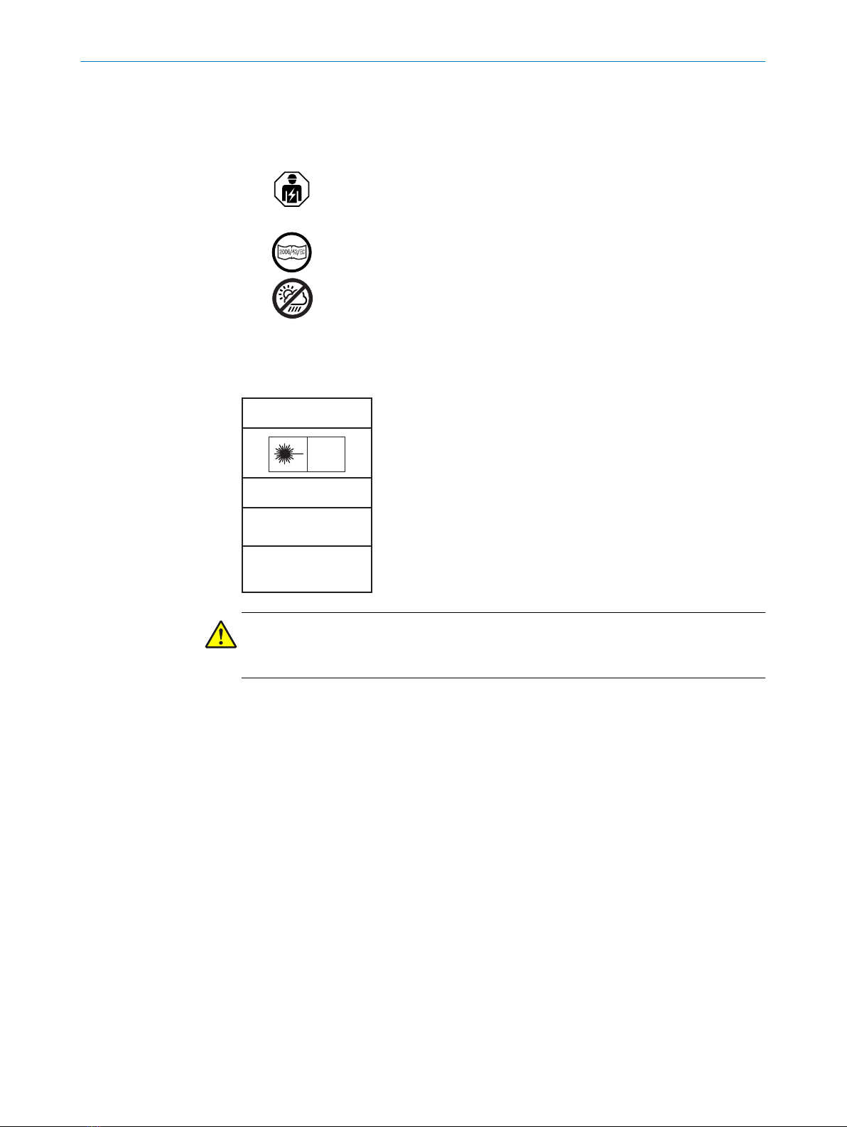
HSE18L:
EN 60825-1:2014
IEC60825-1:2014
LASER CLASS 1
Laser
1
Maximum pulse power < 2,5 mW
Puls length: 4 µs
Wavelength: 650 - 670 nm
Complies with 21 CFR 1040.10
and 1040.11 except for deviations
pursuant to Laser Notice No. 50,
dated June 24, 2007
ATTENTION
WARNING: Interruption, manipulation or incorrect use can lead to hazardous exposure
due to laser radiation.
2 Notes on UL approval
All housing types are Type 1 enclosure.
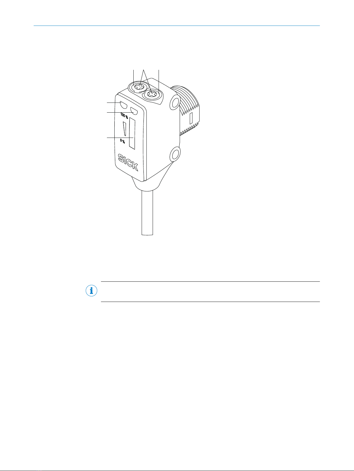
3 Intended use
The HSE18 is an opto-electronic through-beam photoelectric sensor (referred to as
“sensor” in the following) for the optical, non-contact detection of objects, animals,
and persons. A sender (HS18) and a receiver (HE18) are required for operation. If
the product is used for any other purpose or modified in any way, any warranty claim
against SICK AG shall become void.
The HSE18L is an opto-electronic through-beam photoelectric sensor (referred to as
“sensor” in the following) for the optical, non-contact detection of objects. A sender
(HS18) and a receiver (HE18) are required for operation. If the product is used for any
other purpose or modified in any way, any warranty claim against SICK AG shall become
void.
The sensor complies with the Radio Safety Requirements (EMC) for the industrial sector
(Radio Safety Class A). It may cause radio interference if used in a residential area.
GENERAL SAFETY NOTES 1
8017854.1A15 / 2020-12-14 | SICK
Subject to change without notice 5