SICK GRL18 24 Series User manual

OPERATING INSTRUCTION
GRL18
Round photoelectric sensors

Described product
GR18
GRL18
Manufacturer
SICK AG
Erwin-Sick-Str. 1
79183 Waldkirch
Germany
Production location
Legal information
This work is protected by copyright. Any rights derived from the copyright shall be
reserved for SICK AG. Reproduction of this document or parts of this document is
only permissible within the limits of the legal determination of Copyright Law. Any modi‐
fication, abridgment or translation of this document is prohibited without the express
written permission of SICK AG.
The trademarks stated in this document are the property of their respective owner.
© SICK AG. All rights reserved.
Original document
This document is an original document of SICK AG.
2006/42/EC
NO
SAFETY
8016955.1ABM / 21.12.2020 | SICK
Subject to change without notice 3

Contents
1 General safety notes......................................................................... 5
2 Notes on UL approval........................................................................ 5
3 Correct use......................................................................................... 5
4 Commissioning.................................................................................. 5
4.1 Check the application conditions............................................................ 5
4.2 Mounting................................................................................................... 6
4.3 Electronics................................................................................................. 7
4.4 Alignment.................................................................................................. 7
4.5 Adjustment................................................................................................ 7
5 Troubleshooting................................................................................. 8
6 Disassembly and disposal............................................................... 9
7 Maintenance...................................................................................... 9
8 Technical specifications................................................................... 10
8.1 Dimensional drawings.............................................................................. 10
CONTENTS
48016955.1ABM / 21.12.2020 | SICK
Subject to change without notice

1 General safety notes
■Read the operating instructions before commissioning.
■
Connection, mounting, and configuration may only be performed by trained
specialists.
■
2006/42/EC
NO
SAFETY
Not a safety component in accordance with the EU Machinery Directive.
■
Do not install the sensor at locations that are exposed to direct sunlight
or other weather influences, unless this is expressly permitted in the operating
instructions.
■These operating instructions contain information required during the life cycle of
the sensor.
2 Notes on UL approval
UL: Only for use in applications in accordance with NFPA 79. These devices shall be
protected by a 1 A fuse suitable for 30 V DC.
Adapters listed by UL with connection cables are available.
Enclosure type 1.
3 Correct use
The GRL18 is an opto-electronic photoelectric retro-reflective sensor (referred to as
"sensor" in the following) for the optical, non-contact detection of objects, animals, and
persons. A reflector is required for this product to function. If the product is used for any
other purpose or modified in any way, any warranty claim against SICK AG shall become
void.
4 Commissioning
4.1 Check the application conditions
Adjust the distance between the sensor and the reflector according to the correspond‐
ing diagram (x = sensing range, y = operating reserve).
GENERAL SAFETY NOTES 1
8016955.1ABM / 21.12.2020 | SICK
Subject to change without notice 5

1
0 1
(3.28)
2
(6.56)
3
(9.84)
4
(13.12)
5
(16.40)
6
(19.69)
7
(22.97)
8
(26.25)
100
10
Operating reserve
Distance in m (feet)
1
2
34
5
6
Figure 1: H
4.2 Mounting
Mount the sensor and the reflector using suitable mounting brackets (see the SICK
range of accessories). Align the sensor and reflector with each other.
Observe the maximum permissible tightening torque of the sensor of 2.0 Nm for
metal/0.9 Nm for plastic [K].
Figure: K: GRL18-x24x7
Figure: K: GRL18-x24x2
4 COMMISSIONING
68016955.1ABM / 21.12.2020 | SICK
Subject to change without notice

4.3 Electronics
The sensors must be connected in a voltage-free state (VS = 0 V). The information in the
graphics [B] must be observed, depending on the type of connection:
– Male connector connection: pin assignment
– Cable: core color
+ (L+)
Q
- (M)
brn
wht
blu
blk
1
2
3
Q
4
Figure: B: GRL18-x24xx
+ (L+)
Q
- (M)
brn
wht
blu
Q
blk
Figure: B: GRL18-x11xx, -x12xx
Only apply voltage/switch on the power supply (VS > 0 V) once all electrical connections
have been completed. The green LED indicator lights up on the sensor.
Explanations of the connection diagram (Graphic B):
Switching outputs Q and /Q (according to Graphic B):
GRL18-P (PNP: load -> M)
GRL18-N (NPN: load -> L+)
4.4 Alignment
Align the sensor with a suitable reflector. Select the position so that the red emitted
light beam hits the center of the reflector. The sensor must have a clear view of the
reflector, with no object in the path of the beam [see figure 2]. You must ensure that the
optical openings of the sensor and reflector are completely clear.
Figure 2: Alignment
4.5 Adjustment
Sensor with potentiometer:
COMMISSIONING 4
8016955.1ABM / 21.12.2020 | SICK
Subject to change without notice 7

The sensitivity is adjusted with the potentiometer (type: 270°). Clockwise rotation:
operating reserve increased; counterclockwise rotation: operating reserve reduced. We
recommend setting the potentiometer to "Maximum." A lower operating reserve may be
necessary for depolarizing surfaces.
The sensor is adjusted and ready for operation. Refer to graphics C and G to check the
function. If the switching output fails to behave in accordance with graphic C, check
application conditions. See section Fault diagnosis.
Q
(PNP)
(NPN)
Q
q1
0
q
1
0
1
0
1
0
Figure: C
Figure: G
5 Troubleshooting
The Troubleshooting table indicates measures to be taken if the sensor stops working.
Table Fault diagnosis
LED indicator/fault pattern Cause Measures
Green LED does not light up No voltage or voltage below
the limit values
Check the power supply,
check all electrical connec‐
tions (cables and plug connec‐
tions)
Green LED does not light up Voltage interruptions Ensure there is a stable power
supply without interruptions
Green LED does not light up Sensor is faulty If the power supply is OK,
replace the sensor
4 COMMISSIONING
88016955.1ABM / 21.12.2020 | SICK
Subject to change without notice

LED indicator/fault pattern Cause Measures
Yellow LED flashes Sensor is still ready for oper‐
ation, but the operating condi‐
tions are not ideal
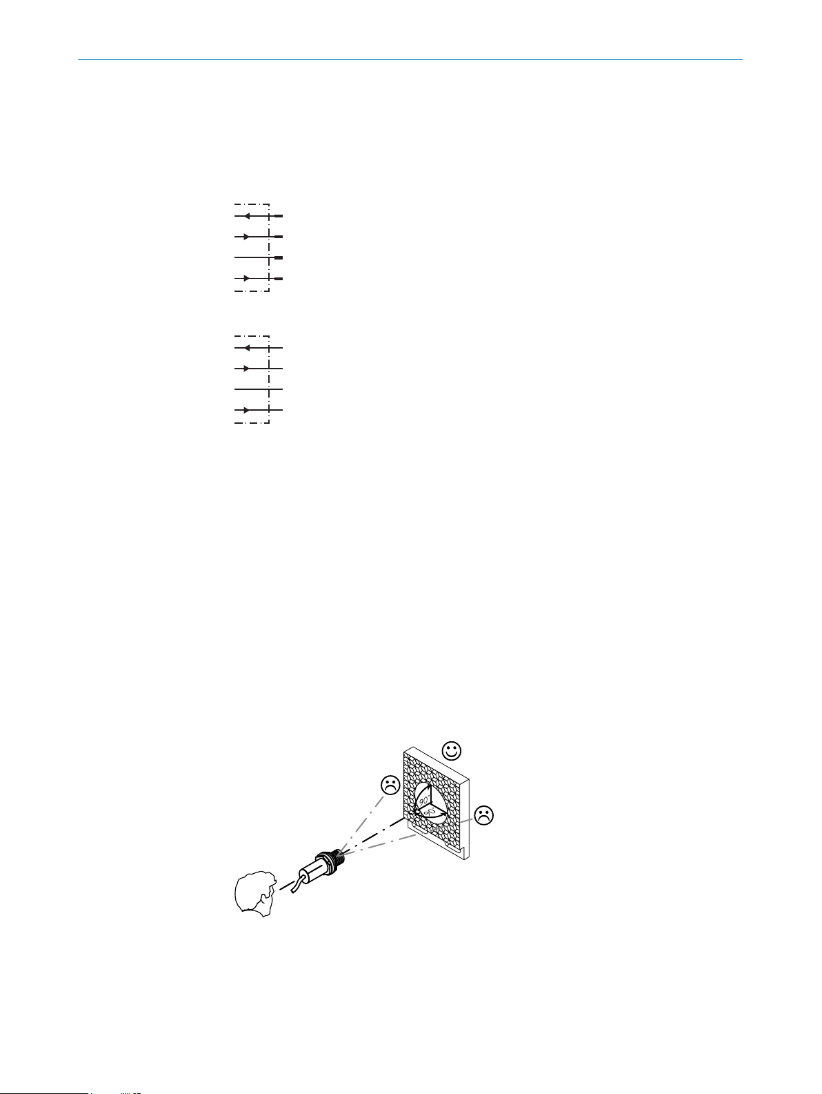
Check the operating condi‐
tions: Fully align the beam
of light (light spot) with the
reflector. / Clean the optical
surfaces (sensor and reflec‐
tor). / Readjust the sensitivity
(potentiometer) / If the poten‐
tiometer is set to the max.
sensing range: Reduce the
distance between the sensor
and the reflector, and check
the reflector type / Reflector
is not suitable for the appli‐
cation in question (we recom‐
mend only using SICK reflec‐
tors) / Check sensing range
and adjust if necessary, see
„Check the application condi‐
tions“, page 5. / Distance
between the sensor and the
reflector is too long
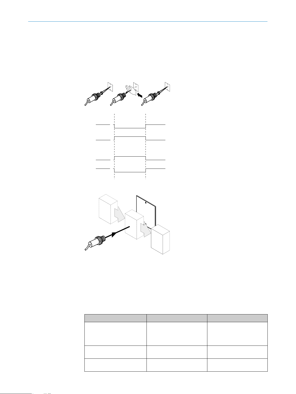
Signal interruptions when
object is detected
Depolarizing property of the
object surface (e.g., tape),
reflection
Reduce sensitivity or change
the position of the sensor
6 Disassembly and disposal
The sensor must be disposed of according to the applicable country-specific regula‐
tions. Efforts should be made during the disposal process to recycle the constituent
materials (particularly precious metals).
NOTE
Disposal of batteries, electric and electronic devices
•According to international directives, batteries, accumulators and electrical or
electronic devices must not be disposed of in general waste.
•The owner is obliged by law to return this devices at the end of their life to the
respective public collection points.
•
WEEE: This symbol on the product, its package or in this document,
indicates that a product is subject to these regulations.
7 Maintenance
SICK sensors are maintenance-free.
We recommend doing the following regularly:
•Clean the external lens surfaces
•Check the screw connections and plug-in connections
No modifications may be made to devices.
Subject to change without notice. Specified product properties and technical data are
not written guarantees.
DISASSEMBLY AND DISPOSAL 6
8016955.1ABM / 21.12.2020 | SICK
Subject to change without notice 9

8 Technical specifications
GRL18
Laser class
Sensing range (with reflector PL80A) 0.06 ... 7.2 m
Sensing range max. (with reflector PL80A) 0.06 ... 7.2 m
Light spot diameter/distance 175 mm / 7 m
Supply voltage UBDC 10 ... 30 V1)
Ripple
Output current Imax. 100 mA
Current consumption
Switching frequency 1,000 / s2)
Max. response time <0.5 ms3)
Enclosure rating IP67
Protection class III4)
Circuit protection A, B, D5)
Ambient operating temperature -25 °C ... + 55 °C
1) Limit values. UB connections reverse-polarity protected. Residual ripple max 5 VPP
2) With light / dark ratio 1:1
3) Signal transit time with resistive load
4) Reference voltage DC 50 V
5) A = UB-connections reverse polarity protected
B = inputs and output reverse-polarity protected
D = outputs overcurrent and short-circuit protected
8.1 Dimensional drawings
Figure 3: GRL18-xxxx2
8 TECHNICAL SPECIFICATIONS
10 8016955.1ABM / 21.12.2020 | SICK
Subject to change without notice

Figure 4: GRL18-xxxx7
TECHNICAL SPECIFICATIONS 8
8016955.1ABM / 21.12.2020 | SICK
Subject to change without notice 11

Beschriebenes Produkt
GR18
GRL18
Hersteller
SICK AG
Erwin-Sick-Str. 1
79183 Waldkirch
Deutschland
Fertigungsstandort
Rechtliche Hinweise
Dieses Werk ist urheberrechtlich geschützt. Die dadurch begründeten Rechte bleiben
bei der Firma SICK AG. Die Vervielfältigung des Werks oder von Teilen dieses Werks
ist nur in den Grenzen der gesetzlichen Bestimmungen des Urheberrechtsgesetzes
zulässig. Jede Änderung, Kürzung oder Übersetzung des Werks ohne ausdrückliche
schriftliche Zustimmung der Firma SICK AG ist untersagt.
Die in diesem Dokument genannten Marken sind Eigentum ihrer jeweiligen Inhaber.
© SICK AG. Alle Rechte vorbehalten.
Originaldokument
Dieses Dokument ist ein Originaldokument der SICK AG.
2006/42/EC
NO
SAFETY
8016955.1ABM / 21.12.2020 | SICK
Subject to change without notice 13

Inhalt
9 Allgemeine Sicherheitshinweise..................................................... 15
10 Hinweise zur UL Zulassung.............................................................. 15
11 Bestimmungsgemäße Verwendung............................................... 15
12 Inbetriebnahme................................................................................. 15
12.1 Einsatzbedingungen prüfen..................................................................... 15
12.2 Montage.................................................................................................... 16
12.3 Elektronik.................................................................................................. 17
12.4 Ausrichtung............................................................................................... 17
12.5 Einstellung................................................................................................. 18
13 Störungsbehebung............................................................................ 18
14 Demontage und Entsorgung............................................................ 19
15 Wartung.............................................................................................. 19
16 Technische Daten.............................................................................. 20
16.1 Maßzeichnungen...................................................................................... 20
INHALT
14 8016955.1ABM / 21.12.2020 | SICK
Subject to change without notice

9 Allgemeine Sicherheitshinweise
■Lesen Sie vor der Inbetriebnahme des Geräts die Betriebsanleitung.
■
Der Anschluss, die Montage und die Konfiguration des Geräts dürfen nur
von geschultem Fachpersonal vorgenommen werden.
■
2006/42/EC
NO
SAFETY
Bei diesem Gerät handelt es sich um kein sicherheitsgerichtetes Bauteil im
Sinne der EU-Maschinenrichtlinie.
■
Installieren Sie den Sensor nicht an Orten, die direkter Sonneneinstrahlung
oder sonstigen Wettereinflüssen ausgesetzt sind, ausser dies ist in der Betriebs‐
anleitung ausdrücklich erlaubt.
■Die vorliegende Betriebsanleitung enthält Informationen, die während des Lebens‐
zyklus der Lichtschranke benötigt werden.
10 Hinweise zur UL Zulassung
UL: Nur zur Verwendung in Anwendungen gemäß NFPA 79. Diese Geräte müssen mit
einer für 30V DC geeigneten 1A-Sicherung abgesichert werden.
Von UL gelistete Adapter mit Anschlusskabeln sind verfügbar.
Enclosure type 1.
11 Bestimmungsgemäße Verwendung
Die GRL18 ist eine optoelektronische Reflexions-Lichtschranke (im Folgenden Sensor
genannt) und wird zum optischen, berührungslosen Erfassen von Sachen, Tieren und
Personen eingesetzt. Zur Funktion wird ein Reflektor benötigt. Bei jeder anderen
Verwendung und bei Veränderungen am Produkt verfällt jeglicher Gewährleistungsan‐
spruch gegenüber der SICK AG.
12 Inbetriebnahme
12.1 Einsatzbedingungen prüfen
Distanz zwischen Sensor und Reflektor mit dem zugehörigen Diagramm [vgl. H] abglei‐
chen (x = Schaltabstand, y = Funktionsreserve).
ALLGEMEINE SICHERHEITSHINWEISE 9
8016955.1ABM / 21.12.2020 | SICK
Subject to change without notice 15

1
0 1
(3.28)
2
(6.56)
3
(9.84)
4
(13.12)
5
(16.40)
6
(19.69)
7
(22.97)
8
(26.25)
100
10
Operating reserve
Distance in m (feet)
1
2
34
5
6
Abbildung 5: H
12.2 Montage
Sensor und Reflektor an geeignete Befestigungswinkel montieren (siehe SICK-Zube‐
hör-Programm). Sensor und Reflektor zueinander ausrichten.
Maximal zulässiges Anzugsdrehmoment des Sensors von 2,0 Nm für Metall / 0,9 Nm
für Kunststoff beachten [vgl. K].
Abbildung: K: GRL18-x24x7
Abbildung: K: GRL18-x24x2
12 INBETRIEBNAHME
16 8016955.1ABM / 21.12.2020 | SICK
Subject to change without notice

12.3 Elektronik
Anschluss der Sensoren muss spannungsfrei (VS = 0 V) erfolgen. Je nach Anschlussart
sind die Informationen in den Grafiken [vgl. B] zu beachten:
– Steckeranschluss: Pinbelegung
– Leitung: Adernfarbe
+ (L+)
Q
- (M)
brn
wht
blu
blk
1
2
3
Q
4
Abbildung: B:GRL18 -x24xx
+ (L+)
Q
- (M)
brn
wht
blu
Q
blk
Abbildung: B: GRL18-x11xx, -x12xx
Erst nach Anschluss aller elektrischen Verbindungen die Spannungsversorgung (VS > 0
V) anlegen bzw. einschalten. Am Sensor leuchtet die grüne Anzeige-LED.
Erläuterungen zum Anschlussschema (Grafik B):
Schaltausgänge Q bzw. /Q (gemäß Grafik B):
GRL18-P (PNP: Last -> M)
GRL18-N (NPN: Last -> L+)
12.4 Ausrichtung
Sensor auf geeigneten Reflektor ausrichten. Positionierung so wählen, dass der rote
Sendelichtstrahl in der Mitte des Reflektors auftrifft. Der Sensor muss freie Sicht
auf den Reflektor haben, es darf sich kein Objekt im Strahlengang befinden [siehe
Abbildung 6]. Es ist darauf zu achten, dass die optischen Öffnungen von Sensor und
Reflektor vollständig frei sind.
Abbildung 6: Ausrichtung
INBETRIEBNAHME 12
8016955.1ABM / 21.12.2020 | SICK
Subject to change without notice 17

12.5 Einstellung
Sensor mit Potentiometer:
Mit dem Potentiometer (Art: 270°) wird die Empfindlichkeit eingestellt. Drehung nach
rechts: Erhöhung der Funktionsreserve, Drehung nach links: Verringerung der Funkti‐
onsreserve. Wir empfehlen, das Potentiometer auf "Maximal" zu stellen. Bei depolarisie‐
renden Oberflächen kann eine geringere Funktionsreserve empfehlenswert sein.
Sensor ist eingestellt und betriebsbereit. Zur Überprüfung der Funktion Grafik C und G
heranziehen. Verhält sich der Schaltausgang nicht gemäß Grafik C, Einsatzbedingungen
prüfen. Siehe Abschnitt Fehlerdiagnose.
Q
(PNP)
(NPN)
Q
q1
0
q
1
0
1
0
1
0
Abbildung: C
Abbildung: G
13 Störungsbehebung
Tabelle Störungsbehebung zeigt, welche Maßnahmen durchzuführen sind, wenn die
Funktion des Sensors nicht mehr gegeben ist.
Tabelle Fehlerdiagnose
Anzeige-LED / Fehlerbild Ursache Maßnahme
grüne LED leuchtet nicht keine Spannung oder Span‐
nung unterhalb der Grenz‐
werte
Spannungsversorgung prüfen,
den gesamten elektrischen
Anschluss prüfen (Leitungen
und Steckerverbindungen)
12 INBETRIEBNAHME
18 8016955.1ABM / 21.12.2020 | SICK
Subject to change without notice

Anzeige-LED / Fehlerbild Ursache Maßnahme
grüne LED leuchtet nicht Spannungsunterbrechungen Sicherstellen einer stabilen
Spannungsversorgung ohne
Unterbrechungen
grüne LED leuchtet nicht Sensor ist defekt Wenn Spannungsversorgung
in Ordnung ist, dann Sensor
austauschen
gelbe LED blinkt Sensor ist noch betriebsbe‐
reit, aber die Betriebsbedin‐
gungen sind nicht optimal
Betriebsbedingungen prüfen:
Lichtstrahl (Lichtfleck) voll‐
ständig auf den Reflektor
ausrichten / Reinigung der
optischen Flächen (Sensor
und Reflektor) / Empfindlich‐
keit (Potentiometer) neu ein‐
stellen / falls Potentiometer
auf max. Schaltabstand ein‐
gestellt: Abstand zwischen
Sensor und Reflektor verrin‐
gern sowie Reflektortyp über‐
prüfen / Reflektor eignet sich
nicht für gewählte Applikation
(wir empfehlen, ausschließlich
SICK-Reflektoren zu verwen‐
den) / Schaltabstand überprü‐
fen und ggf. anpassen, siehe
„Einsatzbedingungen prüfen“,
Seite 15. / Abstand zwischen
Sensor und Reflektor ist zu
groß
Signalunterbrechungen bei
Objektdetektion
Depolarisierende Eigenschaft
der Objektoberfläche (z. B.
Folie), Umspiegelung
Empfindlichkeit reduzieren
oder Sensorposition verän‐
dern
14 Demontage und Entsorgung
Die Lichtschranke muss entsprechend den geltenden länderspezifischen Vorschriften
entsorgt werden. Bei der Entsorgung sollte eine werkstoffliche Verwertung (insbeson‐
dere der Edelmetalle) angestrebt werden.
HINWEIS
Entsorgung von Batterien, Elektro- und Elektronikgeräten
•Gemäß den internationalen Vorschriften dürfen Batterien, Akkus sowie Elektro-
und Elektronikgeräte nicht mit dem Hausmüll entsorgt werden.
•Der Besitzer ist gesetzlich verpflichtet, diese Geräte am Ende ihrer Lebensdauer
bei den entsprechenden öffentlichen Sammelstellen abzugeben.
•
WEEE: Dieses Symbol auf dem Produkt, dessen Verpackung oder im
vorliegenden Dokument gibt an, dass ein Produkt den genannten Vorschriften
unterliegt.
15 Wartung
SICK-Sensoren sind wartungsfrei.
DEMONTAGE UND ENTSORGUNG 14
8016955.1ABM / 21.12.2020 | SICK
Subject to change without notice 19

Wir empfehlen, in regelmäßigen Abständen
•die optischen Grenzflächen zu reinigen
•Verschraubungen und Steckverbindungen zu überprüfen
Veränderungen an Geräten dürfen nicht vorgenommen werden.
Irrtümer und Änderungen vorbehalten. Angegebene Produkteigenschaften und techni‐
sche Daten stellen keine Garantieerklärung dar.
16 Technische Daten
GRL18
Laserklasse
Schaltabstand (mit Reflektor PL80A) 0.06 ... 7.2 m
Schaltabstand max. (mit Reflektor PL80A) 0.06 ... 7.2 m
Lichtfleckdurchmesser/Entfernung 175 mm / 7 m
Versorgungsspannung UBDC 10 ... 30 V1)
Restwelligkeit
Ausgangsstrom Imax. 100 mA
Stromaufnahme
Schaltfrequenz 1,000 / s2)
Ansprechzeit max. <0.5 ms3)
Schutzart IP67
Schutzklasse III4)
Schutzschaltungen A, B, D5)
Betriebsumgebungstemperatur -25 °C ... + 55 °C
1) Grenzwerte. UB-Anschlüsse verpolsicher. Restwelligkeit max. 5 Vss
2) Mit Hell- / Dunkelverhältnis 1:1
3) Signallaufzeit bei ohmscher Last
4) Bemessungsspannung DC 50 V
5) A = UB-Anschlüsse verpolsicher
B = Ein- und Ausgänge verpolsicher
D = Ausgänge überstrom- und kurzschlussfest
16.1 Maßzeichnungen
Abbildung 7: GRL18-xxxx2
16 TECHNISCHE DATEN
20 8016955.1ABM / 21.12.2020 | SICK
Subject to change without notice
This manual suits for next models
4
Table of contents
Languages:
Other SICK Accessories manuals

SICK
SICK TiM35x User manual

SICK
SICK DL100 Pro User manual

SICK
SICK PL240DG-H User manual

SICK
SICK TiM8P Series User manual

SICK
SICK LMS4400 User manual

SICK
SICK WLA26 00 Series User manual

SICK
SICK GRTE18S V Series User manual

SICK
SICK WLD16 User manual

SICK
SICK WTF26 User manual

SICK
SICK IQ80-50BPP-KC0 User manual

SICK
SICK OD1000 User manual

SICK
SICK Bluetooth WLA16 User manual

SICK
SICK WTB4F User manual

SICK
SICK VICOTEC320 Series User manual

SICK
SICK EDS35-2 Series User manual

SICK
SICK GTB6L User manual

SICK
SICK WL24-2 Series User manual

SICK
SICK TiM361S User manual

SICK
SICK WL34 User manual

SICK
SICK UC40-112 Series User manual