SICK SENSICK UM 18-11116 User manual

Änderungen vorbehalten
Angegebene Produkteigenschaften und technische Daten stellen keine
Garantieerklärung dar
UM 18-11116
UM 18-11117
8 011 042.0205 GO KE
DEUTSCH
Ultraschallsensor
mit Analogausgang
Betriebsanleitung
Sicherheitshinweise
‡ Vor der Inbetriebnahme die Betriebsanleitung lesen.
‡ Anschluss, Montage und Einstellung nur durch Fachpersonal.
‡ Gerät bei Inbetriebnahme vor Feuchte und Verunreinigung
schützen.
‡ Kein Sicherheitsbauteil gemäß EU-Maschinenrichtlinie.
Bestimmungsgemäße Verwendung
Der UM 18-1111_ ist ein Ultraschallsensor und wird zum
berührungslosen Erfassen von Sachen,Tieren und Personen
eingesetzt.
Inbetriebnahme
A1 Teach-in Fenstergrenzen
(4 mA, 20 mA bzw. 0V, 10 V)
– Objekt für sensornahe Fenstergrenze vor den Sensor
bringen:
LED1 leuchtet (im Fenster) oder ist aus
(außerhalb Fenster)
– L+ solange an den Steuereingang anlegen: LED2 blinkt,
LED1 behält ihren Zustand
– bis beide LEDs gleichzeitig blinken (nach ca. 3 s)
– L+ von dem Steuereingang entfernen: beide LEDs
blinken wechselseitig
– Objekt für sensorferne Fenstergrenze vor den Sensor
bringen
– erneut L+ an den Steuereingang anlegen: LED1 blinkt,
LED2 ist aus
– nach ca. 1 s L+ von dem Steuereingang entfernen: LED1
leuchtet (im Fenster) oder ist aus (außerhalb Fenster).
Das Fenster mit sensornaher und sensorferner Fenster-
grenze ist dauerhaft gespeichert, der Sensor ist betriebsbe-
reit.
Wird zuerst die sensorferne Grenze und danach die
sensornahe Grenze gelernt, werden die Grenzen intern
getauscht.
Wird die Fensterbreite < 5 mm gelernt, so blinken beide
LEDs für 3 Sekunden gleichzeitig schnell (Fehleranzeige).
Die alten Fenstergrenzen werden beibehalten.
A2 Teach-in maximale Fensterbreite
– Kein Objekt vor den Sensor bringen: LED1 leuchtet (im
Fenster) oder ist aus (außerhalb Fenster)
– L+ solange an den Steuereingang anlegen: LED2 blinkt,
LED1 behält ihren Zustand
– bis beide LEDs gleichzeitig blinken (nach ca. 3 s)
– L+ von dem Steuereingang entfernen: beide LEDs
blinken wechselseitig
– erneut L+ an den Steuereingang anlegen: LED1 blinkt,
LED2 ist aus
– nach ca. 1 s L+ von dem Steuereingang entfernen: LED1
leuchtet (im Fenster) oder ist aus (außerhalb Fenster).
Das Fenster mit minimaler sensornaher Fenstergrenze und
maximaler sensorferner Fenstergrenze ist dauerhaft
gespeichert, der Sensor ist betriebsbereit.
A3 Teach-in Ausgangscharakteristik
(steigend/fallend)
– L+ solange an den Steuereingang anlegen: LED1 blinkt,
LED2 behält ihren Zustand. Nach 3 s blinken beide
LEDs gleichzeitig
– bis beide LEDs wechselseitig schnell blinken (ca. 13 s)
– L+ von dem Steuereingang entfernen: LED2 blinkt
schnell, LED1 zeigt die Ausgangscharakteristik:
LED1 an = steigend
LED1 aus = fallend
– während LED2 schnell blinkt, wird mit jedem Anlegen
von L+ die Ausgangscharakteristik invertiert:
LED1 an = steigend
LED2 aus = fallend
Wird für 10 s nicht L+ angelegt, ist die eingestellte
Ausgangscharakteristik aktiv, der Sensor ist betriebsbereit.
A4 Wechsel zwischenTeach-in und Synchronisation
Eigensynchronisation: Sensoren via PIN 5 verschalten (max.
10 können parallel geschaltet werden). Dadurch wird der
„Detektionsbereich“ vergrößert. Bei Parallelbetrieb der
Sensoren muss der seitliche Montageabstand kleiner 10 cm
betragen. Durch die Synchronisation wird eine Art
„Gitterbetrieb“ realisiert.
– Sensor spannungslos schalten (Betriebsspannung
abschalten)
– M an den Steuereingang anlegen, Betriebsspannung
zuschalten, M weiterhin an den Steuereingang angelegt
halten: LED2 blinkt schnell, LED1 zeigt den Zustand des
Schaltausganges an
– bis beide LEDs gleichzeitig blinken (nach ca. 3 s)
– M von dem Steuereingang entfernen: LED1 blinkt
schnell, LED2 zeigt die Betriebsart an:
LED2 an = Teach-in-Betrieb
LED2 aus = Synchronisationsbetrieb
– während die LED1 schnell blinkt, wird mit jedem
Anlegen von M dieTasterfunktion invertiert:
LED2 an = Teach-in-Betrieb
LED2 aus = Synchronisationsbetrieb
Wird für 10 s nicht M angelegt, ist die eingestellte Funktion
übernommen, der Sensor ist betriebsbereit.
A5 Werkseinstellung
– Sensor spannungslos schalten (Betriebsspannung
abschalten)
– M an den Steuereingang anlegen, Betriebsspannung
zuschalten, M weiterhin an den Steuereingang angelegt
halten: LED2 blinkt schnell, LED1 zeigt den Zustand des
Schaltausganges an. Nach 3 s blinken beide LEDs
gleichzeitig.
– bis beide LEDs den Schaltzustand anzeigen
(nach ca. 13 s)
– M von dem Steuereingang entfernen.
Der Sensor hat seine Werkseinstellung.
Wartung
SICK-Sensoren sind wartungsfrei. Wir empfehlen, in regelmäßi-
gen Abständen
- die Grenzflächen zu reinigen,
-Verschraubungen und Steckverbindungen zu überprüfen.
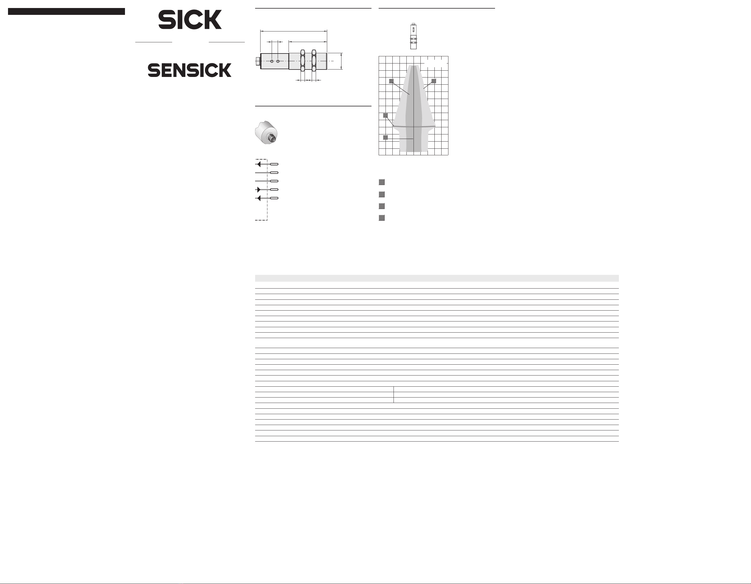
2
1
M18x1
5 5
73,3
47
5
–80 –40 0 40 80
[mm]
50
100
150
200
250
300
350
UM 18-5111_
250 mm
1
2
3
4
2
Betriebstastweite
Grenztastweite
3
1
4
Ausgerichtete Platte
500 x 500 mm2
Rohr-Durchmesser
10 mm
UM 18- 11116 11117
BetrBetr
BetrBetr
Betriebstastwiebstastw
iebstastwiebstastw
iebstastweite (Grenztastweite (Grenztastw
eite (Grenztastweite (Grenztastw
eite (Grenztastweite)eite)
eite)eite)
eite) 30 mm ... 250 mm (< 350 mm)
Ultraschallfrequenz 320 kHz
Auflösung 0,36 mm
Wiederholgenauigkeit typ. ±0,15 % vom Endwert
Genauigkeit ≤2 % vom Endwert
BetrBetr
BetrBetr
Betriebsspanniebsspann
iebsspanniebsspann
iebsspannungung
ungung
ung UV= DC 10 ... 30 V
Restwelligkeit 10 %
Leerstromaufnahme ≤40 mA
Gehäusematerial Messingrohr, vernickelt
Kunststoffteile: PBT
Ultraschallwandler: Polyurethan-
schaum, Epoxydharz mit Glasanteilen
Schutzart nach EN 60529 IP 67
Anschlussart Rundsteckverbinder M12, 5-polig
Anzeigeelemente 2 LEDs
Umgebungstemperatur Betrieb: –25 °C ... +70 °C
Lager: –40 °C ... +85 °C
Gewicht ca. 65 g (mit 2 Muttern)
Steuereingang MF Teach-in
Analogausgang 4 ... 20 mA RL≤ 100 Ω bei 10 V ≤ UV ≤ 20 V
RL≤ 500 Ω bei UV ≥ 20V
0 ... 10 V RL≥ 100 kΩ bei UV ≥ 15 V
Temperaturkompensation ja
Synchronisationsmöglichkeit ja
Funktionsanzeige ja
Tastbetrieb ja
Schalthysterese 2,0 mm ±10 %
Ansprechverzug 32 ms
Bereitschaftsverzug < 300 ms
3
1L+
NC
Q
4
3
2M
brn
blk
blu
5MF
gra
wht
A
BA_UM18_11116_11117.PMD 28.02.05, 11:591

We reserve the right to make changes without prior notification
UM 18-11116
UM 18-11117
8 011 042.0205 GO KE
ENGLISH
Ultrasonic sensor
with analogue outputs
Operating Instructions
Safety Specifications
‡ No safety component in accordance with EU machine
guidelines.
‡ Read the operating instructions before starting operation.
‡ Connection, assembly, and settings only by competent
technicians.
‡ Protect the device against moisture and soiling when
operating.
Proper Use
The UM 18-1111_ is an ultrasonic sensor and is used for
non-contact detection of objects, animals, and people.
Starting Operation
A1 Teach-in window limits
(4 mA, 20 mA or 0V, 10 V)
– Place the object for window distance near the sensor in
front of the sensor. LED1 lights (in window) or is off
(outside of window)
– connect L+ at the control input until: LED2 blinks, LED1
retains its state
– until both LEDs blink simultaneously (after approx. 3 s)
– remove L+ from the control input: both LEDs blink
alternately
– place the object for window distance far from the
sensor in front of the sensor.
– connect L+ at the control input again: LED1 blinks, LED2
is off
– remove L+ from the control input after approx. 1 s:
LED1 lights (in window) or is off (outside of window).
The window with the window limit near the sensor and far
from it is stored permanently, and the sensor is ready to
operate.
If the limit far from the sensor is first taught and then the
sensor near the limit, the limits are exchanged internally.
If the window width < 5 mm is taught, both LEDs blink
simultaneously fast for 3 seconds (error display).The old
window limits are maintained.
A2 Teach-in maximum window width
– Do not place any object in front of the sensor: LED1
lights (in window) or is off (outside of window)
– connect L+ at the control input until: LED2 blinks, LED1
retains its state
– until both LEDs blink simultaneously (after approx. 3 s)
– remove L+ from the control input: both LEDs blink
alternately
– connect L+ at the control input again: LED1 blinks, LED2
is off
– remove L+ from the control input after approx. 1 s:
LED1 lights (in window) or is off (outside of window).
The window with the minimum window limit near the
sensor and the maximum limit far from it is stored
permanently, and the sensor is ready to operate.
A3 Teach-in output characteristics
(rising/falling)
– Connect L+ at the control input until: LED1 blinks, LED2
retains its state. Both LEDs blink simultaneously after 3 s
– until both LEDs blink alternately fast (approx. 13 s)
– remove L+ from the control input: LED2 blinks fast,
LED1 displays the output characteristic
LED1 on = rising
LED1 off = falling
– while the LED2 blinks fast, the output characteristic is
inverted each time L+ is connected.
LED1 on = rising
LED2 off = falling
If L+ is not connected for 10 s, the set output
characteristic remains active; the sensor is ready to
operate.
A4 Switch between teach-in and synchronization
Self-synchronization: Connect sensors via PIN 5 (max. 10
can be switched parallel). As a result, the “detection range”
is increased.When there is parallel operation of the
sensors, the installation distance sideways must be smaller
than 10 cm. A type of “grid operation” is achieved via the
synchronization.
– Switch off the power to the sensor (switch off the
operating voltage)
– connect M to the control input, switch on the operating
voltage, keep M connected to the control input LED2
blinks fast, LED1 displays the state of the switching
output
– until both LEDs blink simultaneously (after approx. 3 s)
– remove M from the control input: LED1 blinks fast, LED2
displays the operating mode:
LED2 on = Teach-in mode
LED2 off = Synchronization mode
– while the LED1 blinks fast, the scanner function is
inverted each time M is connected.
LED2 on = Teach-in mode
LED2 off = Synchronization mode
If M is not connected for 10 s, the set output function is
adopted; the sensor is ready to operate.
A5 Ex-works setting
– Switch off the power to the sensor (switch off the
operating voltage)
– connect M to the control input, switch on the operating
voltage, keep M connected to the control input LED2
blinks fast, LED1 displays the state of the switching
output. Both LEDs blink simultaneously after 3 s.
– until both LEDs display the switching state (after approx.
13 s)
– remove M from the control input.
The sensor has its ex-works setting.
Maintenance
SICK sensors do not require any maintenance.We recommend
that you clean the external lens surfaces and check the screw
connections and plug-in connections at regular intervals.
2
1
–80 –40 0 40 80
[mm]
50
100
150
200
250
300
350
UM 18-5111_
250 mm
1
2
3
4
2
Operating distance
Maximum scanning
distance
3
1
4
Aligned plate
500 x 500 mm2
Tube diameter 10 mm
UM 18- 11116 11117
OperOper
OperOper
Operating distanceating distance
ating distanceating distance
ating distance 30 mm ... 250 mm (< 350 mm)
(maxim(maxim
(maxim(maxim
(maximum scanning distance)um scanning distance)
um scanning distance)um scanning distance)
um scanning distance)
Ultrasonic frequency 320 kHz
Resolution 0.36 mm
Reproducibility typ. ±0.15 % of final value
Accuracy ≤2 % of final value
OperOper
OperOper
Operating vating v
ating vating v
ating voltageoltage
oltageoltage
oltage VS= DC 10 ... 30 V
Residual ripple 10 %
Idle current consumption ≤40 mA
Housing material Brass tube, nickel plated
Plastic parts: PBT
Ultrasonic converter: polyure-
thane foam, epoxy resin with
glass content
Enclosure rating to EN 60529 IP 67
Connection type Plug M12, 5-pin
Display elements 2 LEDs
Ambient temperature Operating: –25 °C ... +70 °C
Storage: –40 °C ... +85 °C
Weight 65 g approx. (with 2 nuts)
Control input MF Teach-in
Analogue output 4 ... 20 mA RL≤ 100 Ω at 10 V ≤ VS ≤ 20 V
RL≤ 500 Ω at VS ≥ 20V
0 ... 10 V RL≥ 100 kΩ at VS ≥ 15 V
Temperature compensation yes
Synchronisation option yes
Functional display yes
Scanning Mode yes
Switching hysteresis 2.0 mm ±10 %
Response time 32 ms
Standby delay < 300 ms
3
1L+
NC
Q
4
3
2M
brn
blk
blu
5MF
gra
wht
A
M18x1
5 5
73.3
47
5
BA_UM18_11116_11117.PMD 28.02.05, 11:592
This manual suits for next models
1
Table of contents
Languages:
Other SICK Accessories manuals