LED indicator/fault pattern /
LED indicator/fault pattern
Cause /
Cause
Measures /
Measures
Yellow LED lights up, no object in
the path of the beam /
Yellow LED lights up, no object in
the path of the beam
Remission capability of the back‐
ground is excessive /
Remission capability of the back‐
ground is excessive
Check changes to the back‐
ground. Reduce the sensitivity of
the sensor or use sensors with
background suppression /
Check changes to the back‐
ground. Reduce the sensitivity of
the sensor or use sensors with
background suppression
Object is in the path of the beam,
yellow LED does not light up /
Object is in the path of the beam,
yellow LED does not light up
Sensitivity is set too low or dis‐
tance between the sensor and the
object is too long /
Sensitivity is set too low or dis‐
tance between the sensor and the
object is too long
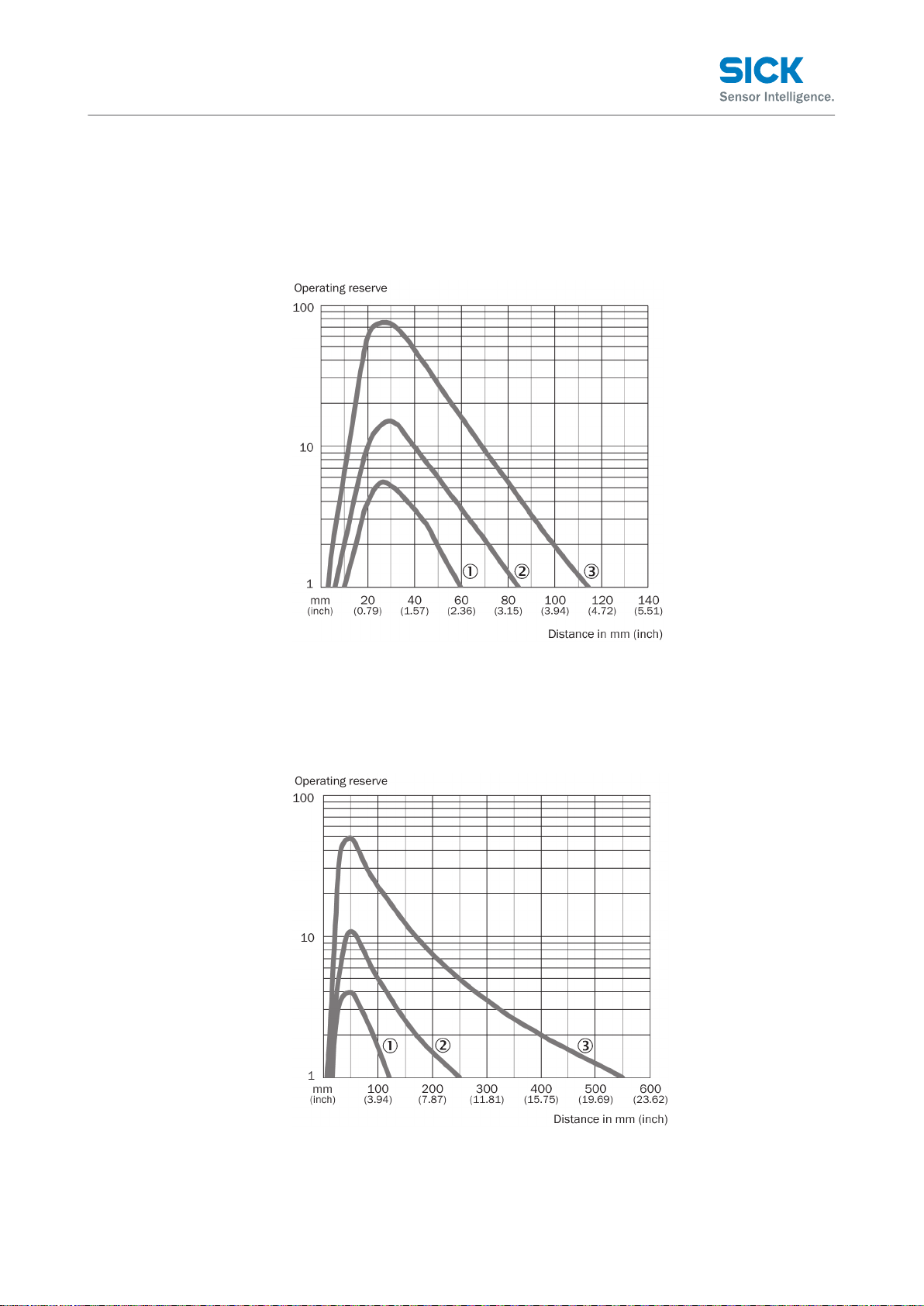
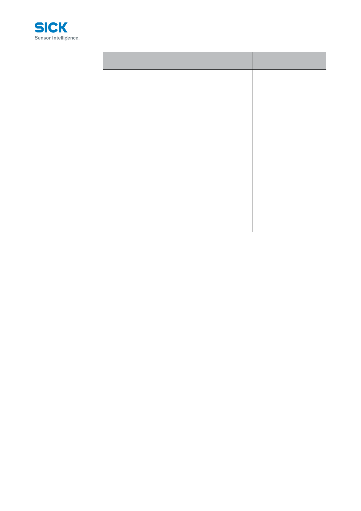
Increase the sensing range, take
note of the distance between the
sensor and the background, see
Graphic E /
Increase the sensing range, take
note of the distance between the
sensor and the background, see
Graphic E
Object is in the path of the beam,
yellow LED does not light up /
Object is in the path of the beam,
yellow LED does not light up
Remission capability of the object
is insufficient /
Remission capability of the object
is insufficient
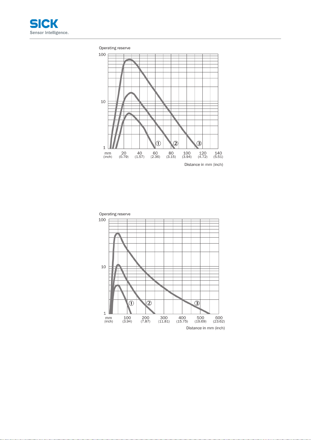
Increase the sensing range, take
note of the distance between the
sensor and the background, see
Graphic E /
Increase the sensing range, take
note of the distance between the
sensor and the background, see
Graphic E
8 Disassembly and disposal
The sensor must be disposed of according to the applicable country-specific regulations. Efforts
should be made during the disposal process to recycle the constituent materials (particularly pre‐
cious metals).
9 Maintenance
SICK sensors are maintenance-free.
We recommend doing the following regularly:
1. Clean the external lens surfaces
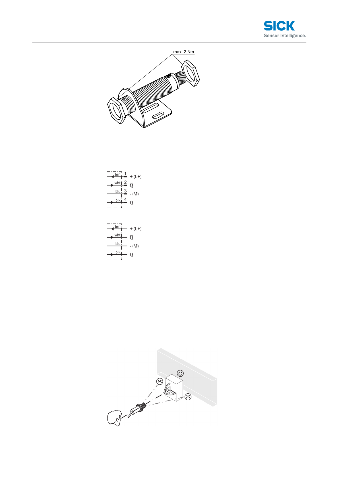
2. Check the screw connections and plug-in connections
No modifications may be made to devices.
Subject to change without notice. Specified product properties and technical data are not written
guarantees.
Reflexions-Lichttaster
Betriebsanleitung
12 Sicherheitshinweise
■Vor der Inbetriebnahme die Betriebsanleitung lesen.
■Anschluss, Montage und Einstellung nur durch Fachpersonal.
■Kein Sicherheitsbauteil gemäß EU-Maschinenrichtlinie. Nur zur Verwendung in Anwendungen
gemäß NFPA 79. Von UL gelistete Adapter mit Anschlusskabeln sind verfügbar. Enclosure
type 1
Disassembly and disposal
Irrtuemer | SICK 7