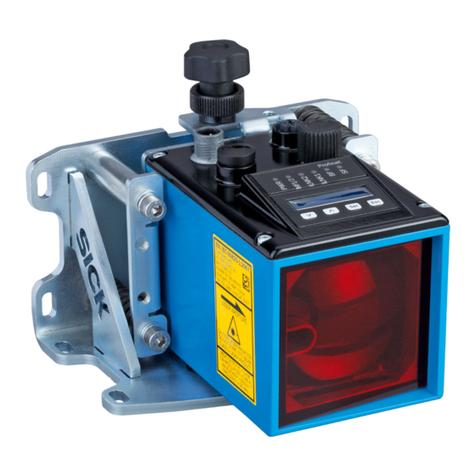
SICK safeVisionary2 User manual

OPERATING INSTRUCTIONS
safeVisionary2
Safety camera sensor

Described product
safeVisionary2
Manufacturer
SICK AG
Erwin-Sick-Str. 1
79183 Waldkirch
Germany
Legal information
This work is protected by copyright. Any rights derived from the copyright shall be
reserved for SICK AG. Reproduction of this document or parts of this document is
only permissible within the limits of the legal determination of Copyright Law. Any modi‐
fication, abridgment or translation of this document is prohibited without the express
written permission of SICK AG.
The trademarks stated in this document are the property of their respective owner.
© SICK AG. All rights reserved.
Original document
This document is an original document of SICK AG.
2O P E R A T I N G I N S T R U C T I O N S | safeVisionary2 8025919/1I9E/2023-01-09 | SICK
Subject to change without notice
Contents
1 About this document........................................................................ 7
1.1 Scope......................................................................................................... 7
1.2 Target groups of these operating instructions........................................ 7
1.3 Further information................................................................................... 7
1.4 Symbols and document conventions...................................................... 7
2 Safety information............................................................................ 9
2.1 General safety notes................................................................................ 9
2.2 Intended use............................................................................................. 10
2.3 Inappropriate use..................................................................................... 10
2.4 Cybersecurity............................................................................................ 10
2.5 Requirements for the qualification of personnel.................................... 11
3 Product description........................................................................... 12
3.1 Device overview........................................................................................ 12
3.2 Structure and function............................................................................. 12
3.3 Status indicators....................................................................................... 14
3.4 Product characteristics............................................................................ 14
3.4.1 Coordinate system................................................................... 14
3.4.2 Field types................................................................................ 16
3.5 Example applications............................................................................... 18
4 Project planning................................................................................ 22
4.1 Manufacturer of the machine.................................................................. 22
4.2 Operating entity of the machine.............................................................. 22
4.3 Design........................................................................................................ 22
4.3.1 Installation site........................................................................ 23
4.3.2 Protection from overheating.................................................... 23
4.3.3 Protection from interference................................................... 24
4.3.4 Preventing unprotected areas................................................. 25
4.3.5 Distance to the floor................................................................ 25
4.3.6 Extension of the protective field when influenced by retro‐
reflectors or headlights........................................................... 26
4.3.7 Timing for monitoring case switching..................................... 26
4.3.8 Approach direction................................................................... 27
4.3.9 Minimum distance for stationary applications...................... 28
4.3.10 Hazardous area protection...................................................... 29
4.3.11 Hazardous point protection..................................................... 31
4.3.12 Access protection.................................................................... 33
4.3.13 Mobile hazardous area protection.......................................... 35
4.3.14 Fall protection.......................................................................... 37
4.4 Integrating the equipment into the electrical control............................. 39
4.4.1 Electromagnetic compatibility................................................. 39
4.4.2 Voltage supply.......................................................................... 40
CONTENTS
8025919/1I9E/2023-01-09 | SICK O P E R A T I N G I N S T R U C T I O N S | safeVisionary2 3
Subject to change without notice

4.4.3 OSSDs....................................................................................... 40
4.4.4 Control inputs........................................................................... 41
4.4.5 Universal inputs, universal outputs, universal I/Os.............. 44
4.4.6 Restart interlock...................................................................... 44
4.4.7 External device monitoring (EDM).......................................... 44
4.5 Integration into the network..................................................................... 45
4.5.1 Network topology..................................................................... 45
4.5.2 Network services and ports.................................................... 45
4.6 Testing plan............................................................................................... 45
4.6.1 Planning the thorough check during commissioning and in
certain situations..................................................................... 46
4.6.2 Planning the regular thorough check..................................... 47
4.6.3 Notes on the tests................................................................... 47
5 Mounting............................................................................................. 51
5.1 Mounting the heat sink............................................................................ 51
5.2 Mounting the device................................................................................. 51
6 Electrical installation........................................................................ 53
6.1 Connecting................................................................................................ 53
6.1.1 System connection.................................................................. 53
6.1.2 Ethernet connection................................................................ 54
7 Configuration..................................................................................... 55
7.1 Delivery state............................................................................................ 55
7.2 Safety Designer configuration software.................................................. 55
7.2.1 Installing Safety Designer....................................................... 55
7.2.2 Creating a project..................................................................... 55
7.2.3 User interface.......................................................................... 56
7.2.4 Configuring devices online...................................................... 56
7.2.5 Configuring devices offline...................................................... 57
7.2.6 User groups.............................................................................. 57
7.3 Add device tile........................................................................................... 58
7.4 Open the device window – configure devices......................................... 58
7.5 Overview.................................................................................................... 59
7.6 Network settings....................................................................................... 60
7.6.1 Ethernet.................................................................................... 60
7.7 Reading configuration.............................................................................. 60
7.8 Identification............................................................................................. 60
7.9 Monitoring settings................................................................................... 61
7.10 3D editor.................................................................................................... 63
7.10.1 Adjusting the mounting settings............................................. 65
7.10.2 Calibration data and Contours................................................ 66
7.10.3 Fields and ROI.......................................................................... 67
7.11 Inputs and outputs, local......................................................................... 70
7.11.1 Output signals.......................................................................... 70
CONTENTS
4O P E R A T I N G I N S T R U C T I O N S | safeVisionary2 8025919/1I9E/2023-01-09 | SICK
Subject to change without notice
7.11.2 Input signals............................................................................. 71
7.11.3 Further settings for some signals........................................... 72
7.12 Monitoring cases...................................................................................... 73
7.12.1 Settings for monitoring case tables........................................ 73
7.12.2 Settings for monitoring cases................................................. 74
7.12.3 Defining input conditions........................................................ 74
7.12.4 Configuring cut-off paths......................................................... 74
7.12.5 Assigning field sets and ROI sets........................................... 75
7.12.6 Assigning a defined cut-off behavior...................................... 75
7.13 Data output............................................................................................... 75
7.14 Transferring a configuration..................................................................... 76
7.15 Verify configuration................................................................................... 76
7.16 Starting and stopping safety function..................................................... 77
7.17 Report........................................................................................................ 78
7.18 Service....................................................................................................... 79
7.18.1 Assigning or changing passwords........................................... 79
7.18.2 Resetting the password........................................................... 79
8 Commissioning.................................................................................. 80
8.1 Switching on.............................................................................................. 80
8.2 Check during commissioning and modifications.................................... 80
9 Operation............................................................................................ 81
9.1 Status indicators....................................................................................... 81
10 Maintenance...................................................................................... 83
10.1 Regular cleaning....................................................................................... 83
10.2 Regular thorough check........................................................................... 83
11 Troubleshooting................................................................................. 84
11.1 Fault indicators......................................................................................... 84
11.2 Diagnostics using Safety Designer.......................................................... 84
11.2.1 Data recorder........................................................................... 85
11.2.2 Message history....................................................................... 86
12 Decommissioning............................................................................. 89
12.1 Disposal..................................................................................................... 89
13 Technical data.................................................................................... 90
13.1 Data sheet................................................................................................. 90
13.2 Response time.......................................................................................... 93
13.3 Course of the OSSD test over time.......................................................... 94
13.4 Scanning range......................................................................................... 95
13.5 Dimensional drawings.............................................................................. 97
14 Ordering information........................................................................ 99
14.1 Scope of delivery....................................................................................... 99
CONTENTS
8025919/1I9E/2023-01-09 | SICK O P E R A T I N G I N S T R U C T I O N S | safeVisionary2 5
Subject to change without notice

14.2 Ordering information for the safety camera sensor............................... 99
15 Accessories........................................................................................ 100
15.1 Brackets.................................................................................................... 100
15.2 Heat sink................................................................................................... 100
15.3 Cleaning agent.......................................................................................... 100
16 Glossary.............................................................................................. 101
17 Annex.................................................................................................. 104
17.1 Conformities and certificates................................................................... 104
17.1.1 EU declaration of conformity................................................... 104
17.2 Note on standards.................................................................................... 104
17.3 Licenses.................................................................................................... 105
17.4 Checklist for initial commissioning and commissioning........................ 106
18 List of figures..................................................................................... 107
19 List of tables....................................................................................... 108
CONTENTS
6O P E R A T I N G I N S T R U C T I O N S | safeVisionary2 8025919/1I9E/2023-01-09 | SICK
Subject to change without notice
1 About this document
1.1 Scope
Product
This document applies to the following products:
•Product code: safeVisionary2
•“Operating instructions” type label entry: 8025917
Document identification
Document part number:
•This document: 8025919
•Available language versions of this document: 8025917
You can find the current version of all documents at www.sick.com.
1.2 Target groups of these operating instructions
Some sections of these operating instructions are intended for certain target groups.
However, the entire operating instructions are relevant for intended use of the product.
Table 1: Target groups and selected sections of these operating instructions
Target group Sections of these operating instructions
Project developers (planners, developers,
designers)
"Project planning", page 22
"Configuration", page 55
"Technical data", page 90
"Accessories", page 100
Installers "Mounting", page 51
Electricians "Electrical installation", page 53
Safety experts (such as CE authorized repre‐
sentatives, compliance officers, people who
test and approve the application)
"Project planning", page 22
"Configuration", page 55
"Commissioning", page 80
"Technical data", page 90
"Checklist for initial commissioning and com‐
missioning", page 106
Operators "Operation", page 81
"Troubleshooting", page 84
Maintenance personnel "Maintenance", page 83
"Troubleshooting", page 84
1.3 Further information
www.sick.com
The following information is available via the Internet:
•Data sheets and application examples
•CAD files and dimensional drawings
•Certificates (such as the EU declaration of conformity)
•Guide for Safe Machinery. Six steps to a safe machine
•Safety Designer (software for configuring safety solutions made by SICK AG)
1.4 Symbols and document conventions
The following symbols and conventions are used in this document:
ABOUT THIS DOCUMENT 1
8025919/1I9E/2023-01-09 | SICK O P E R A T I N G I N S T R U C T I O N S | safeVisionary2 7
Subject to change without notice

Safety notes and other notes
DANGER
Indicates a situation presenting imminent danger, which will lead to death or serious
injuries if not prevented.
WARNING
Indicates a situation presenting possible danger, which may lead to death or serious
injuries if not prevented.
CAUTION
Indicates a situation presenting possible danger, which may lead to moderate or minor
injuries if not prevented.
NOTICE
Indicates a situation presenting possible danger, which may lead to property damage if
not prevented.
NOTE
Indicates useful tips and recommendations.
Instructions to action
bThe arrow denotes instructions to action.
1. The sequence of instructions for action is numbered.
2. Follow the order in which the numbered instructions are given.
✓The check mark denotes the result of an instruction.
LED symbols
These symbols indicate the status of an LED:
oThe LED is off.
ÖThe LED is flashing.
OThe LED is illuminated continuously.
1 ABOUT THIS DOCUMENT
8O P E R A T I N G I N S T R U C T I O N S | safeVisionary2 8025919/1I9E/2023-01-09 | SICK
Subject to change without notice
2 Safety information
2.1 General safety notes
Product integration
DANGER
The product can not offer the expected protection if it is integrated incorrectly.
bPlan the integration of the product in accordance with the machine requirements
(project planning).
bImplement the integration of the product in accordance with the project planning.
Laser class 1
CAUTION
If any operating or adjusting devices other than those specified in this document are
used or other methods are employed, this can lead to dangerous exposure to radiation.
bOnly use the operating or adjusting devices specified in this document.
bOnly follow the methods specified in this document.
bDo not open the housing, except for the purposes of the installation and mainte‐
nance work specified in these operating instructions.
LASER
1
Figure 1: Laser class 1
This device complies with the following standards:
•IEC60825-1:2014
•21CFR1040.10 and 1040.11, except compliance with IEC60825-1:2014, as
described in Laser Notice No.56 dated May 8, 2019
The laser is eye-safe.
Mounting and electrical installation
DANGER
Death or severe injury due to electrical voltage and/or an unexpected startup of the
machine
bMake sure that the machine is (and remains) disconnected from the voltage
supply during mounting and electrical installation.
bMake sure that the dangerous state of the machine is and remains switched off.
SAFETY INFORMATION 2
8025919/1I9E/2023-01-09 | SICK O P E R A T I N G I N S T R U C T I O N S | safeVisionary2 9
Subject to change without notice

Repairs and modifications
DANGER
Improper work on the product
A modified product may not offer the expected protection if it is integrated incorrectly.
bApart from the procedures described in this document, do not repair, open, manip‐
ulate or otherwise modify the product.
2.2 Intended use
The safety camera sensor is an electro-sensitive protective equipment (ESPE) and is
suitable for the following applications:
•Hazardous point protection
•Hazardous area protection
•Mobile hazardous area protection
•Access protection
•Fall protection for mobile applications
The product may be used in safety functions.
The product may be used in industrial environments. An industrial environment is
an area that is not open to the public and where only adult, instructed persons are
present.
The product must only be used within the limits of the prescribed and specified techni‐
cal specifications and operating conditions at all times.
Incorrect use, improper modification or manipulation of the product will invalidate any
warranty from SICK; in addition, any responsibility and liability of SICK for damage and
secondary damage caused by this is excluded.
2.3 Inappropriate use
The safety camera sensor works as an indirect protective measure and cannot provide
protection from ejected parts or from emitted radiation. Transparent objects are not
detected.
The safety camera sensor is not suitable for the following applications, among others:
•Outdoors
•Underwater
•In explosion-hazardous areas
2.4 Cybersecurity
Overview
To protect against cybersecurity threats, it is necessary to continuously monitor and
maintain a comprehensive cybersecurity concept. A suitable concept consists of organi‐
zational, technical, procedural, electronic, and physical levels of defense and considers
suitable measures for different types of risks. The measures implemented in this
product can only support protection against cybersecurity threats if the product is used
as part of such a concept.
You will find further information at www.sick.com/psirt, e.g.:
•General information on cybersecurity
•Contact option for reporting vulnerabilities
•Information on known vulnerabilities (security advisories)
2 SAFETY INFORMATION
10 O P E R A T I N G I N S T R U C T I O N S | safeVisionary2 8025919/1I9E/2023-01-09 | SICK
Subject to change without notice
2.5 Requirements for the qualification of personnel
The product must be configured, installed, connected, commissioned, and serviced by
qualified safety personnel only.
Project planning
You need safety expertise to implement safety functions and select suitable products
for that purpose. You need expert knowledge of the applicable standards and regula‐
tions.
Mounting, electrical installation and commissioning
You need suitable expertise and experience. You must be able to assess if the machine
is operating safely.
Configuration
You need suitable expertise and experience. You must be able to assess if the machine
is operating safely.
Operation and maintenance
You need suitable expertise and experience. You must be instructed in machine oper‐
ation by the machine operator. For maintenance, you must be able to assess if the
machine is operating safely.
SAFETY INFORMATION 2
8025919/1I9E/2023-01-09 | SICK O P E R A T I N G I N S T R U C T I O N S | safeVisionary2 11
Subject to change without notice

3 Product description
3.1 Device overview
Device overview
1
2
3
24
5
Figure 2: Device overview
1Illumination unit
2Status indicators: Status LEDs
3Camera module
4System connection: Voltage supply, OSSDs and universal IO
5Ethernet connection
Further topics
•"Electrical installation", page 53
•"Mounting", page 51
3.2 Structure and function
Structure and function
The safety camera sensor is an electro-sensitive protective device (ESPE) which scans
its surroundings three-dimensionally using infrared laser beams.
As soon as an object is situated in the protective field, the camera sensor signals
the detection by means of a signal change at the safety output. The machine or its
controller must safely analyze the signals (for example using a safety controller or a
safety relay) and stop the dangerous state.
The camera sensor operates according to the optical time-of-flight measurement princi‐
ple. It emits light pulses at regular, very short intervals. If the light strikes an object,
it is reflected. The camera sensor receives the reflected light. The camera sensor
calculates the distance to the object based on the time interval between the moment of
transmission and moment of receipt (∆t).
Field of view
The camera sensor has a field of view with an aperture angle of 68° × 58° (horizontal
× vertical).
For protective field evaluation, the field of view of the camera sensor is limited to 68°
× 42°. The full 68° × 58° field of view is available for all other safety functions, field
types, and for data output.
Detection zones of different sizes are created depending on distance z.
3 PRODUCT DESCRIPTION
12 O P E R A T I N G I N S T R U C T I O N S | safeVisionary2 8025919/1I9E/2023-01-09 | SICK
Subject to change without notice

x
y
z
Figure 3: Size of the detection zone
Table 2: Size of the detection zone
Distance z Field of view
68° × 58°
Limited field of view (protective
field)
68° × 42°
Size x Size y Size x Size y
0.2m 0.27m 0.22m 0.27m 0.15m
0.5m 0.68m 0.56m 0.68m 0.39m
1.0m 1.35m 1.11m 1.35m 0.77m
1.5m 2.03m 1.67m 2.03m 1.14m
2.0m 2.7m 2.22m 2.7m 1.51m
4.0m 5.4m 4.44m 5.4m 3.02m
Optical axis
The optical axis is perpendicular to the front screen of the camera module (see figure 3,
page 13, z-axis).
Resolution
The object resolution indicates the minimum size that an object must be to allow it to
be detected safely.
The resolution can be set to various values to suit the intended purpose.
Further topics
•"Preventing unprotected areas", page 25
PRODUCT DESCRIPTION 3
8025919/1I9E/2023-01-09 | SICK O P E R A T I N G I N S T R U C T I O N S | safeVisionary2 13
Subject to change without notice

3.3 Status indicators
Status indicators
OSSD1
OSSD2
LNK/ACT
DIAG
OSSD1
OSSD2
LNK/ACT
DIAG
Figure 4: Status indicators
Table 3: Status indicators
LEDs Color Function
OSSD1 Green/yellow/red OSSD pair 1 status
OSSD2 Green/yellow/red OSSD pair 2 status
LNK/ACT Yellow/green Ethernet status
DIAG Green/yellow/red Diagnostics status
Warning field status
Further topics
•"Status indicators", page 81
•"Fault indicators", page 84
3.4 Product characteristics
3.4.1 Coordinate system
Origin of the device coordinate system
The coordinate origin of the device coordinate system is at the point where the optical
axis and the camera front screen (outer surface) intersect.
The Z axis runs along the optical axis. Looking in the direction of the optical axis, the
X-axis points to the left and the Y-axis points upwards.
3 PRODUCT DESCRIPTION
14 O P E R A T I N G I N S T R U C T I O N S | safeVisionary2 8025919/1I9E/2023-01-09 | SICK
Subject to change without notice

x
y
z
Figure 5: Origin of the device coordinate system
Device coordinates and world coordinates
Device coordinate system
The device coordinates specify the position of an object relative to the
sensor.
World coordinate system
The world coordinates specify the position of an object relative to the world
(e.g., machine surroundings).
You set the position and orientation of the safety camera sensor relative to the world
coordinate system using the SafetyDesigner.
x
y
z
x
y
z
Figure 6: Device coordinate system in the world coordinate system
Further topics
•"Dimensional drawings", page 97
•"Adjusting the mounting settings", page 65
PRODUCT DESCRIPTION 3
8025919/1I9E/2023-01-09 | SICK O P E R A T I N G I N S T R U C T I O N S | safeVisionary2 15
Subject to change without notice

3.4.2 Field types
Overview
A safety camera sensor continuously checks whether people or objects are present in
one or more areas. The areas to be checked are called fields. A distinction is made
between the field types below, depending on the application type.
Protective field
Table 4: Protective field
Purpose Detection and protection of people
Safe switch off
(according to ISO
13849-1)
Yes
Safety-related param‐
eters
PLc (ISO13849-1), SIL1 (IEC61508)
Maximum scanning
range
(Z axis)
2m
4m in Increased scanning range mode
Field size Configurable via the configuration software.
Field of view 68° × 42°
Description The protective field is the area in which the test object specified by the
manufacturer is detected by the electro-sensitive protective equipment
(ESPE). As soon as the electro-sensitive protective device detects an
object in the protective field, it switches the associated safety outputs
to the OFF state. This signal can be passed to controllers resulting in
the dangerous state coming to an end, e.g. to stop the machine or the
vehicle.
Contour detection field
Table 5: Contour detection field
Purpose Fall protection Detection and protection of peo‐
ple in stationary applications
Safe switch off
(according to ISO
13849-1)
Yes
Safety-related param‐
eters
PLc (ISO13849-1), SIL1 (IEC61508)
Maximum scanning
range
(Z axis)
2m
4m in Increased scanning range
mode
2m
4m in Increased scanning range
mode
Field size Configurable via the configuration software.
Field of view 68° × 58°
3 PRODUCT DESCRIPTION
16 O P E R A T I N G I N S T R U C T I O N S | safeVisionary2 8025919/1I9E/2023-01-09 | SICK
Subject to change without notice
Purpose Fall protection Detection and protection of peo‐
ple in stationary applications
Description The contour detection field can, for
example, protect AGVs from falling.
The contour detection field mon‐
itors a contour of the environ‐
ment. The electro-sensitive protec‐
tive device switches the associated
safety outputs to the OFF state if
a contour does not correspond to
the set specifications, e.g. because
a door or flap is open.
The contour detection field can
detect and protect people in
stationary applications using a
taught-in reference background.
The contour detection field mon‐
itors a contour of the environ‐
ment. The electro-sensitive protec‐
tive device switches the associ‐
ated safety outputs to the OFF
state if a contour does not corre‐
spond to the configured require‐
ments, e.g., because a person is
present in the contour detection
field. The person is obscuring the
taught-in reference background.
In stationary applications, the contour detection field can be used to detect contamina‐
tion on the front screens of the device.
Region of interest (ROI)
Table 6: Region of interest (ROI)
Purpose Measurement data output Safe distance check
Safe switch off
(according to ISO
13849-1)
No Yes
Safety-related param‐
eters
– PLc (ISO13849-1), SIL1
(IEC61508)
Maximum scanning
range
(Z axis)
4m
Field size 10 pixels × 10pixels
Field of view 68° × 58°
Description The ROI determines distance values and checks them for plausibility.
The ROI function can transmit
absolute distance values and
quality information via the meas‐
urement data output.
The ROI function can monitor devi‐
ations from a specified distance
value. In the event of a devia‐
tion, the associated safety outputs
switch to the OFF state.
Warning field
Table 7: Warning field
Purpose Use for automation purposes
Safe switch off
(according to ISO
13849-1)
No
Safety-related param‐
eters
–
Maximum scanning
range
(Z axis)
7.3m
Field size Configurable via the configuration software.
Field of view 68° × 58°
PRODUCT DESCRIPTION 3
8025919/1I9E/2023-01-09 | SICK O P E R A T I N G I N S T R U C T I O N S | safeVisionary2 17
Subject to change without notice

Purpose Use for automation purposes
Description The warning field monitors larger areas than the protective field. Simple
switching functions can be triggered with the warning field, e.g. a warn‐
ing light or an acoustic signal can be triggered if a person approaches,
even before the person enters the protective field.
Further topics
•"Scanning range", page 95
•"Fields", page 67
•"ROIs (region of interest)", page 69
3.5 Example applications
Hazardous point protection
In hazardous point protection, the approach is detected very close to the hazardous
point.
The advantage of this type of protective device is that it is possible to have a short
minimum distance and the operator can work more ergonomically.
Hazardous area protection
In hazardous area protection, people are detected if they stay in a defined area.
This type of protective device is suitable for machines, where it is possible to see a
hazardous area completely from the reset pushbutton. When the hazardous area is
entered, a stop signal is triggered and starting is prevented
Figure 7: Example of hazardous area protection
Mobile hazardous area protection
Mobile hazardous area protection is suitable for AGVs to protect people when vehicles
are moving or docking at a fixed station.
3 PRODUCT DESCRIPTION
18 O P E R A T I N G I N S T R U C T I O N S | safeVisionary2 8025919/1I9E/2023-01-09 | SICK
Subject to change without notice
Figure 8: Example of mobile hazardous area protection - personal protection
Collision protection (not safety-related)
The safety camera sensor can detect objects in front of the vehicle and thereby protect
the AGV from collisions.
Figure 9: Collision protection example
Access protection
In access protection, people are detected if their whole body passes through the
protective field.
This type of protective device is used for the protection of access to hazardous areas. A
stop signal is initiated if the hazardous area is entered.
PRODUCT DESCRIPTION 3
8025919/1I9E/2023-01-09 | SICK O P E R A T I N G I N S T R U C T I O N S | safeVisionary2 19
Subject to change without notice

S
Figure 10: Example of access protection
Fall protection
The fall protection is suitable for AGVs. The ESPE stops the vehicle as soon as the con‐
tour in the contour detection field does not correspond to the requirements because,
for example, there is an opening in the floor in the direction of travel.
Figure 11: Fall protection example
ROI measurement function
The ROI measurement function provides safe distance measurement values for flexible
applications. ROIs (pixel areas) 2 are configured in the field of view of the camera
system. Within the ROIs, the measuring function calculates safe distance values 1.
The safe distance values are compared internally with configured limits (ROI tolerance
3 PRODUCT DESCRIPTION
20 O P E R A T I N G I N S T R U C T I O N S | safeVisionary2 8025919/1I9E/2023-01-09 | SICK
Subject to change without notice
Table of contents
Other SICK Accessories manuals