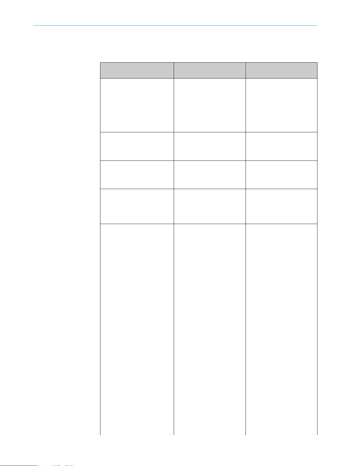
8 Table Fault diagnosis
LED indicator/fault pattern /
LED indicator/fault pattern
Cause /
Cause
Measures /
Measures
Green LED does not light up /
Green LED does not light up
No voltage or voltage below
the limit values /
No voltage or voltage below
the limit values
Check the power supply,
check all electrical connecti‐
ons (cables and plug connecti‐
ons) /
Check the power supply,
check all electrical connecti‐
ons (cables and plug connecti‐
ons)
Green LED does not light up /
Green LED does not light up
Voltage interruptions /
Voltage interruptions
Ensure there is a stable power
supply without interruptions /
Ensure there is a stable power
supply without interruptions
Green LED does not light up /
Green LED does not light up
Sensor is faulty /
Sensor is faulty
If the power supply is OK, re‐
place the sensor /
If the power supply is OK, re‐
place the sensor
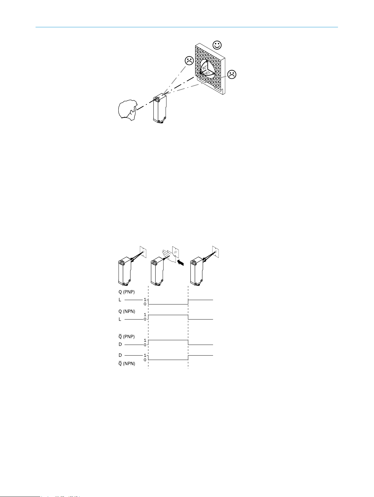
Green LED lights up, no output
signal when object is detec‐
ted /
Green LED lights up, no output
signal when object is detected
Test input (TI) is not connec‐
ted properly /
Test input (TI) is not connec‐
ted properly
See the note on connecting
the TI /
See the note on connecting
the TI
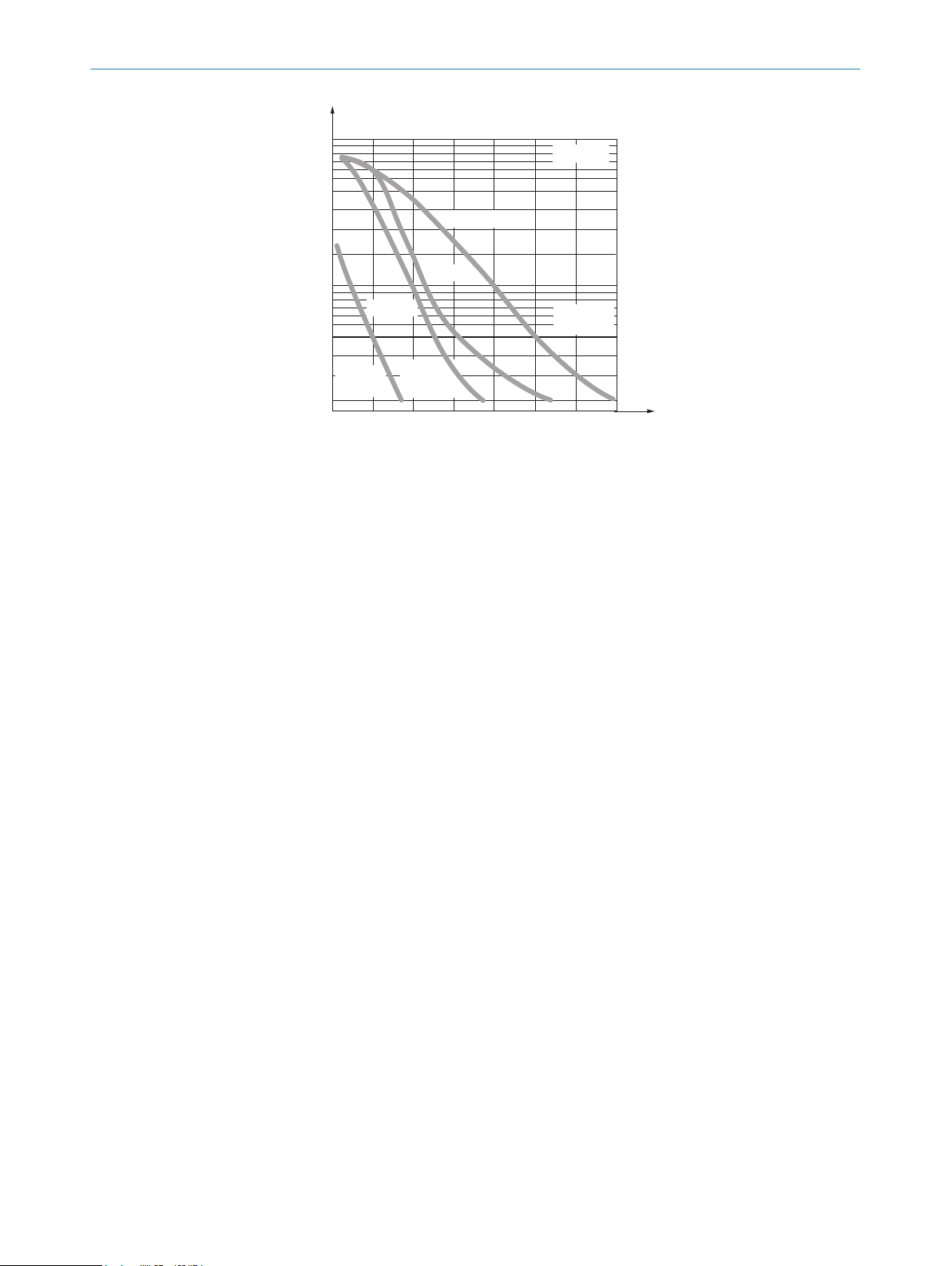
Yellow LED flashes; if Alarm is
present then take note of the
corresponding output signal /
Yellow LED flashes; if Alarm is
present then take note of the
corresponding output signal
Sensor is still ready for opera‐
tion, but the operating conditi‐
ons are not ideal /
Sensor is still ready for opera‐
tion, but the operating conditi‐
ons are not ideal
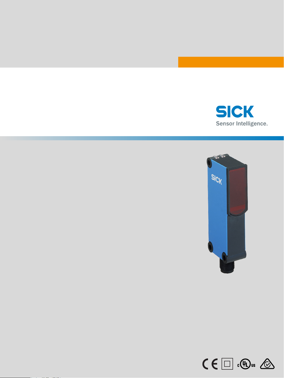
Check the operating conditi‐
ons: Fully align the beam of
light (light spot) with the re‐
flector. / Clean the optical sur‐
faces (sensor and reflector). /
Readjust the sensitivity (po‐
tentiometer) / If the potentio‐
meter is set to the max. sen‐
sing range: Reduce the dis‐
tance between the sensor and
the reflector, and check the re‐
flector type against graphic
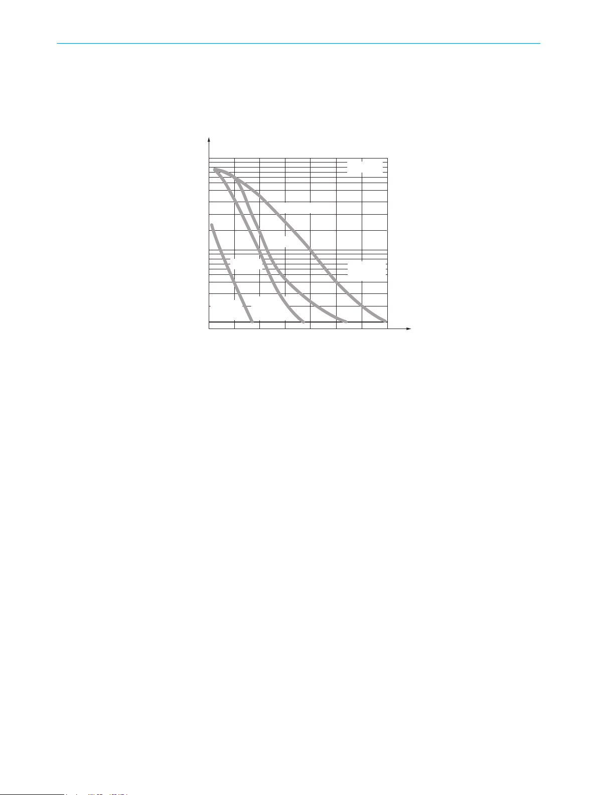
H. / Reflector is not suitable
for the application in question
(we recommend only using
SICK reflectors) / Check sen‐
sing range and adjust if ne‐
cessary; see graphic H. / Dis‐
tance between the sensor and
the reflector is too long /
Check the operating conditi‐
ons: Fully align the beam of
light (light spot) with the re‐
flector. / Clean the optical sur‐
faces (sensor and reflector). /
Readjust the sensitivity (po‐
tentiometer) / If the potentio‐
meter is set to the max. sen‐
sing range: Reduce the dis‐
tance between the sensor and
the reflector, and check the re‐
flector type against graphic
H. / Reflector is not suitable
TABLE FAULT DIAGNOSIS 8
8010585.YM42 | SICK
Subject to change without notice 5