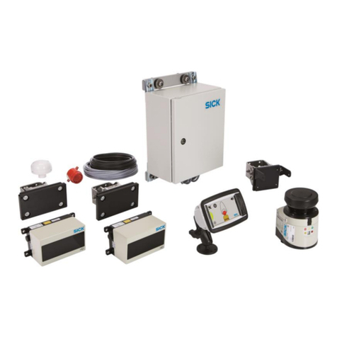
SICK FOS-HVS Series User manual

OPERATING INSTRUCTIONS
FOS-HVS
Quality control system

Described product
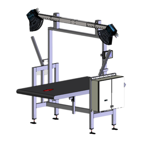
FOS-HVS Foreign Object Detection System
•Mono1600
•Duo1600
•Duo2400
Manufacturer
SICK AG
Erwin-Sick-Str. 1
79183 Waldkirch
Germany
Legal information
This work is protected by copyright. Any rights derived from the copyright shall be
reserved for SICK AG. Reproduction of this document or parts of this document is
only permissible within the limits of the legal determination of Copyright Law. Any modi‐
fication, abridgment or translation of this document is prohibited without the express
written permission of SICK AG.
The trademarks stated in this document are the property of their respective owner.
© SICK AG. All rights reserved.
Original document
This document is an original document of SICK AG.
2O P E R A T I N G I N S T R U C T I O N S | FOS-HVS 8027445/V1-0/2022-06-15 | SICK
Subject to change without notice
Contents
1 About this document........................................................................ 6
1.1 Limitation of liability................................................................................. 6
1.2 Function of this document....................................................................... 6
1.3 Target groups............................................................................................ 6
1.4 Related applicable documents................................................................ 6
1.5 Further information................................................................................... 7
1.6 Symbols and document conventions...................................................... 7
2 Safety information............................................................................ 8
2.1 Basic safety instructions.......................................................................... 8
2.2 Warnings on the device............................................................................ 9
2.3 Notes on the laser.................................................................................... 9
2.4 Intended use............................................................................................. 10
2.5 Protective devices..................................................................................... 10
2.6 Requirements for the qualification of personnel.................................... 11
2.7 Warranty.................................................................................................... 11
2.8 RoHS Directive.......................................................................................... 11
2.9 Cybersecurity............................................................................................ 11
3 Product description........................................................................... 12
3.1 Scope of delivery....................................................................................... 12
3.2 Product characteristics............................................................................ 12
3.3 Typical system structure........................................................................... 12
3.4 System components................................................................................. 13
3.4.1 Measuring head....................................................................... 13
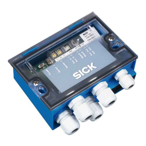
3.4.2 Evaluation unit SIM4000........................................................ 14
3.4.3 SID120 display device............................................................. 15
4 Mounting............................................................................................. 16
4.1 Important information.............................................................................. 16
4.2 System requirements............................................................................... 16
5 Electrical installation........................................................................ 17
5.1 Important information.............................................................................. 17
6 Commissioning.................................................................................. 18
6.1 Important information.............................................................................. 18
6.2 Configuring the system............................................................................. 18
7 Operation............................................................................................ 19
7.1 Structure of the user interfaces............................................................... 19
7.2 Higher-level functions............................................................................... 20
7.2.1 Structure of the configuration interface................................. 20
7.2.1.1 Title bar................................................................... 20
7.2.1.2 Menu area............................................................... 20
CONTENTS
8027445/V1-0/2022-06-15 | SICK O P E R A T I N G I N S T R U C T I O N S | FOS-HVS 3
Subject to change without notice

7.2.1.3 Main window........................................................... 21
7.2.1.4 Status bar................................................................ 21
7.2.2 Application menu group............................................................ 21
7.2.2.1 Settings page............................................................ 21
7.3 Master SIM operation (master side)........................................................ 22
7.3.1 Application menu group............................................................ 23
7.3.1.1 Status page.............................................................. 23
7.3.1.2 PLC Status page........................................................ 23
7.3.1.3 PLC Simulation page.................................................. 24
7.4 Display operation (visualization).............................................................. 24
7.4.1 System start............................................................................. 26
7.4.1.1 Switching on the system......................................... 26
7.4.1.2 Logging on to the system....................................... 26
7.4.2 Inspection process and result display.................................... 28
7.4.3 Inspection page: sample application windows........................ 28
7.4.4 System messages on the SID................................................. 31
7.5 Configuration of the SIMs........................................................................ 32
7.5.1 Graphic operation.................................................................... 32
7.5.2 Image display functions........................................................... 33
7.5.2.1 Additional information about the image................ 34
7.5.3 Application menu group............................................................ 35
7.5.3.1 Run Cam1/Run Cam 2 page..................................... 35
7.5.4 Article menu group .................................................................. 38
7.5.4.1 Article page ............................................................. 38
7.5.4.2 Camera page............................................................ 41
7.5.4.3 Block page ............................................................... 44
7.5.4.4 Test Article page ....................................................... 46
7.5.5 Alignment menu group.............................................................. 46
7.5.5.1 Higher-level functions............................................. 46
7.5.5.2 Global Align page...................................................... 47
7.5.5.3 Align 3E page............................................................ 49
7.5.5.4 Align CC page............................................................ 53
7.5.5.5 Align PA page............................................................ 56
7.5.6 Basic ROI menu group............................................................... 58
7.5.6.1 Basic ROI page.......................................................... 58
7.5.6.2 Selector page............................................................ 63
7.5.7 Special Feature menu group...................................................... 64
7.5.7.1 ROI Simple page........................................................ 64
7.5.7.2 ROI Circle page......................................................... 66
7.5.7.3 ROI Screw page......................................................... 70
7.5.7.4 ROI Seal page........................................................... 72
7.5.8 Checks menu group.................................................................. 76
7.5.8.1 Higher-level functions............................................. 76
7.5.8.2 FOD (Foreign Object Detection) page..................... 77
7.5.9 Device menu group................................................................... 79
CONTENTS
4O P E R A T I N G I N S T R U C T I O N S | FOS-HVS 8027445/V1-0/2022-06-15 | SICK
Subject to change without notice

7.5.9.1 Ranger3 - Calibration page......................................... 79
7.5.10 General menu group................................................................. 80
7.5.10.1 App State page......................................................... 80
7.5.10.2 Logger page.............................................................. 81
7.5.10.3 Image Storage page................................................... 82
7.5.10.4 FTP Client page......................................................... 82
7.5.10.5 System page............................................................. 83
7.5.10.6 Info page.................................................................. 85
8 Maintenance...................................................................................... 86
8.1 Important information.............................................................................. 86
8.2 System functions...................................................................................... 86
8.3 Visual inspection of the cables................................................................ 86
8.4 Ranger3 camera maintenance................................................................ 86
8.5 Laser unit maintenance........................................................................... 87
9 Troubleshooting................................................................................. 89
9.1 Troubleshooting the Ranger3 camera..................................................... 89
9.2 Helping support in the event of a fault.................................................... 89
10 Decommissioning............................................................................. 90
11 Technical data.................................................................................... 91
11.1 Data sheet................................................................................................. 91
11.2 Dimensional drawings.............................................................................. 92
11.2.1 FOS-HVS measuring head....................................................... 92
11.2.2 SID120..................................................................................... 93
11.2.3 SIM4000.................................................................................. 94
12 Spare parts......................................................................................... 95
13 Annex.................................................................................................. 96
13.1 User levels with different rights............................................................... 96
13.2 Test sequence........................................................................................... 98
13.3 Control bits process diagram................................................................... 99
13.4 Control bits IN........................................................................................... 99
13.5 Control bits OUT........................................................................................ 99
13.6 Data OUT................................................................................................... 100
CONTENTS
8027445/V1-0/2022-06-15 | SICK O P E R A T I N G I N S T R U C T I O N S | FOS-HVS 5
Subject to change without notice

1 About this document
1.1 Limitation of liability
Applicable standards and regulations, the latest technological developments, and our
many years of knowledge and experience have all been taken into account when
assembling the data and information contained in this document.
The manufacturer accepts no liability for damage caused by:
•Failure to observe this document.
•Non-compliance with notes and regulations.
•Unauthorized mounting and installation.
•Unauthorized technical and other changes.
•Use of unauthorized spare parts, wear and tear parts, and accessories.
•Unauthorized changes, adjustments, and/or manipulations of software.
The actual scope of delivery may differ from the features and illustrations shown here
where special variants are involved, if optional extras have been ordered, or as a result
of the latest technical changes.
1.2 Function of this document
This document describes the following product:
FOS-HVS Foreign Object Detection System
This document describes the function of the HVS application from the point of view
of the system operator. The documentation includes the information that the system
operator receives about an inspection. In addition, this document describes the means
by which a system operator can influence the behavior of the system.
bThe document must be made available to all those who work with the product.
bRead through the document carefully and ensure that you have full understood the
content before working with the product.
1.3 Target groups
This document is intended for qualified persons who install, commission, operate and
maintain the product.
1.4 Related applicable documents
NOTE
The documents can be found at www.sick.com/[PART NUMBER].
Other documents relevant for the product
•System specification
°Circuit diagram
°Technical data
°Repair manual
•Operating instructions of the system components
Document Title Part number
Operating instructions Ranger3 3D Machine Vision 8020774
Operating instructions SIM4000 Sensor Integration
Machine
8019317
1 ABOUT THIS DOCUMENT
6O P E R A T I N G I N S T R U C T I O N S | FOS-HVS 8027445/V1-0/2022-06-15 | SICK
Subject to change without notice
Document Title Part number
Operating instructions SID120 Sensor Integration
Display
8023944
1.5 Further information
NOTE
The product page can be found at www.sick.com/[PRODUCT NUMBER].
The following information is available depending on the product:
•Data sheets
•These operating instructions in all available languages
•CAD files and dimensional drawings
•Certificates (e.g., declaration of conformity)
•Other publications
•Software
•Accessories
1.6 Symbols and document conventions
Warnings and other notes
DANGER
Indicates a situation presenting imminent danger, which will lead to death or serious
injuries if not prevented.
WARNING
Indicates a situation presenting possible danger, which may lead to death or serious
injuries if not prevented.
CAUTION
Indicates a situation presenting possible danger, which may lead to moderate or minor
injuries if not prevented.
NOTICE
Indicates a situation presenting possible danger, which may lead to property damage if
not prevented.
NOTE
Highlights useful tips and recommendations as well as information for efficient and
trouble-free operation.
Instructions to action
bThe arrow denotes instructions to action.
1. The sequence of instructions is numbered.
2. Follow the order in which the numbered instructions are given.
✓The tick denotes the results of an action.
ABOUT THIS DOCUMENT 1
8027445/V1-0/2022-06-15 | SICK O P E R A T I N G I N S T R U C T I O N S | FOS-HVS 7
Subject to change without notice

2 Safety information
2.1 Basic safety instructions
DANGER
Mechanically moving system components in the inspection cell
bBefore setting up and configuring the system, switch off the inspection cell
DANGER
The product uses one or more line lasers of laser class 2.
The human eye is not at risk when briefly exposed to the radiation for up to 0.25sec‐
onds. Exposure to the laser beam for longer periods of time may cause damage to the
retina. The laser radiation is harmless to human skin.
bNever look directly into the laser beam.
bNever point the laser beam at people’s eyes.
bDuring commissioning or maintenance work, suitable eye protection must be
worn.
bAvoid laser beam reflection caused by reflective surfaces, especially during
assembly and alignment work.
bDo not use optical instruments.
bDo not open the housing.
bCurrent national regulations regarding laser protection must be observed.
DANGER
Danger from electrical voltage
Risk of electrical shock. Contact will result in death, burns or shock.
bElectrical work may only be performed on the system by qualified specialist per‐
sonnel.
bBefore working on electrical components, observe the five safety rules:
°Disconnect
°Secure against being switched back on.
°Ensure that there is no voltage.
°Ground and short-circuit.
°Cover or enclose live parts in the vicinity
WARNING
Risk of injury and damage caused by electrical current
Due to equipotential bonding currents, incorrect earthing can lead to the following
dangers and faults: Voltage is applied to the metal housing, cable fires due to cable
shields heating up, the product and other devices become damaged.
bGenerate the same ground potential at all grounding points.
bGround the equipotential bonding via the functional ground connection with a low
impedance.
Special local conditions
bThe local laws, regulations, technical rules and internal company operating instruc‐
tions at the usage site must be observed.
2 SAFETY INFORMATION
8O P E R A T I N G I N S T R U C T I O N S | FOS-HVS 8027445/V1-0/2022-06-15 | SICK
Subject to change without notice
Storage of documents
bThis document and further technical documentation/information
°Must be kept available for reference.
°Must be handed on to new operating entities/new specialist personnel.
2.2 Warnings on the device
CAUTION
There are warnings on the device.
bRead and observe the notes in these operating instructions concerning the rele‐
vant warning.
bDo not remove or cover warning labels.
bReplace damaged or missing labels.
The rules for affixing laser warning labels of laser class 2 apply.
The following warning signs are included in the scope of delivery of the system (two of
each).
26 mm x 52mm 25mm x 70mm
bPermanently affix the warning signs in the area of the system or near the laser
unit in accordance with their purpose and ensure that they are clearly visible and
legible during normal operation, maintenance and service work.
bAffix the label in such a way that it is legible without exposure to dangerous laser
radiation.
2.3 Notes on the laser
Important information
WARNING
If any operating or adjusting devices other than those specified here are used or other
methods are employed, this can lead to dangerous exposure to radiation.
Overview
The product is equipped with one or more class 2 lasers according to EN/IEC
60825-1:2014 (DIN EN 60825-1:2015) and complies with 21 CFR1040.10 with the
exception of the deviations listed in the Laser Notice No. 50, dated June 24,2007.
Class 2 laser products emit a visible beam in the wavelength range between 400 nm ...
700 nm in which eye protection is normally provided by averting reactions such as
natural eyelid closure.
Class 2 laser products normally do not cause eye injury, but they may pose a hazard
due to glare and temporary loss of vision caused by the laser pulse.
The eyelid closure reflex of the human eye occurs within 0.25seconds after the impact
of the Class 2 laser beam and provides adequate protection. It is possible, however, to
suppress the eyelid closure reflex and to look into the laser long enough to cause harm
to the eye.
SAFETY INFORMATION 2
8027445/V1-0/2022-06-15 | SICK O P E R A T I N G I N S T R U C T I O N S | FOS-HVS 9
Subject to change without notice

When working with a Class 2 laser, the generally applicable regulations and notes on
operational safety regarding laser protection apply.
bPerform installation in accordance with laser safety regulations.
bAvoid glare in the work area in all life cycles.
bSuitably shield or cover the affected areas. The area may need to be cordoned
off, if necessary. In this way, possible secondary hazards due to reflection from
machine parts, for example, can be reduced or eliminated.
Laser specifications
Red laser Green laser Blue laser
Wavelength (nm) 660 520 405
Power (mW) 80 70 75
Switching off the laser
The laser is switched on and off by the evaluation unit via the modulation pin and is
only switched on when it is needed for a scan during an inspection. Switching off the
laser unit in phases in which it is not required serves to optimize the laser service life.
NOTE
Switching off the laser via the modulation pin is only a functionality to extend the laser
service life, but is not a safety-related function according to the Machinery Directive.
bTo switch off the laser, disconnect the power supply of the overall system.
2.4 Intended use
WARNING
The product must only be used for the intended use. Non-intended use can pose a
hazard to people and cause damage to the device.
The FOS-HVS (Forein Object Detection System) for foreign body detection consists of
a number of different hardware and software components for product and process
optimization in the manufacturing industry. Foreign objects are reliably detected on a
variety of surfaces. The product is only suitable for use in industrial environments.
SICK AG assumes no liability for losses or damage arising from the use of the product,
either directly or indirectly. This applies in particular to use of the product that does not
conform to its intended purpose and is not described in this documentation. Incorrect
use, improper modification, or tampering with the system will invalidate any warranty
offered by SICK AG.
NOTE
Intended use also includes observance of these operating instructions, in particular the
safety notes as well as the repair and maintenance requirements.
2.5 Protective devices
The product is designed in a way that allows for safe operation. Protective devices
reduce potential risks to the maximum possible extent.
2 SAFETY INFORMATION
10 O P E R A T I N G I N S T R U C T I O N S | FOS-HVS 8027445/V1-0/2022-06-15 | SICK
Subject to change without notice
2.6 Requirements for the qualification of personnel
•Qualified persons have the specialist training, skills, experience and knowledge
of the relevant regulations and standards needed to be able to perform work
assigned to them and to identify and avoid any potential dangers independently.
•Electricians have the professional training, skills, experience and knowledge of the
relevant standards and provisions needed to work on electrical systems and to
detect and avoid any potential dangers independently.
2.7 Warranty
No warranty claims will be accepted if:
•The safety notes and measures in this document are not observed.
•Parts or components of the FOS-HVS Foreign Object Detection System have been
installed, mounted or modified without authorization.
•The FOS-HVS Foreign Object Detection System has been altered or modified.
•The software has been modified, customized, and/or tampered with without
authorization.
2.8 RoHS Directive
This product has been designed for specific applications in large industrial plants
according to
Article 2 (4) e, RoHS 2011/65/EU, and must therefore only be used in such plants.
The product is neither suitable nor approved for use outside of these systems. SICK
therefore cannot provide any warranty or accept any liability whatsoever for such use.
2.9 Cybersecurity
Overview
To protect against cybersecurity threats, it is necessary to continuously monitor and
maintain a comprehensive cybersecurity concept. A suitable concept consists of organi‐
zational, technical, procedural, electronic, and physical levels of defense and considers
suitable measures for different types of risks. The measures implemented in this
product can only support protection against cybersecurity threats if the product is used
as part of such a concept.
You will find further information at www.sick.com/psirt, e.g.:
•General information on cybersecurity
•Contact option for reporting vulnerabilities
•Information on known vulnerabilities (security advisories)
SAFETY INFORMATION 2
8027445/V1-0/2022-06-15 | SICK O P E R A T I N G I N S T R U C T I O N S | FOS-HVS 11
Subject to change without notice

3 Product description
3.1 Scope of delivery
NOTICE
bAfter delivery, inspect the product for transport damage and report any such
damage immediately.
bCheck that the delivery includes all components listed on the delivery note.
3.2 Product characteristics
The FOS-HVS Foreign Object Detection System is used to detect foreign objects on
the surface of high-voltage batteries, which can lead to damage in the further course.
The system consists of one or more system heads, each with a control and evaluation
unit, one or two Ranger3 cameras, and a line laser. The use of multiple parallel
system heads enables objects of different dimensions to be inspected, and inspection
tasks with varying requirements with regard to resolution and detection quality to be
achieved.
Figure 1: FOS-HVS Foreign Object Detection System
Variant Number of system heads
Mono 1600*2 single heads
(2 Ranger3)
Duo 1600 2 double heads
(4 Ranger3)
Duo 2400 3 double heads
(6 Ranger3)
*currently not yet available
3.3 Typical system structure
The following figure shows the typical system structure and the hardware components
used.
The upper SIM4000 probe combination (2) is the master (SIM_Left_Master). The
SIM4000 probe combination at the bottom of the picture is optional and only available
in a system with 3 heads.
3 PRODUCT DESCRIPTION
12 O P E R A T I N G I N S T R U C T I O N S | FOS-HVS 8027445/V1-0/2022-06-15 | SICK
Subject to change without notice

Figure 2: Typical system structure
1SIM4000 Sensor Integration Machine
2Measuring head, comprising a Ranger3 and line laser
3Ranger3 3D Machine Vision
4Line laser
5Encoder signal distributor
6Encoder
7SID120 Sensor Visualization
8Network switch
9Signal transmission with higher-level PLC
3.4 System components
3.4.1 Measuring head
Overview
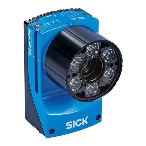
Each measuring head consists of one or two Ranger3 cameras (1) and one line laser
(2).
Figure 3: FOS-HVS measuring head
1Ranger3
2Line laser
PRODUCT DESCRIPTION 3
8027445/V1-0/2022-06-15 | SICK O P E R A T I N G I N S T R U C T I O N S | FOS-HVS 13
Subject to change without notice

The measuring head consists of the Ranger3 cameras, the laser unit including mount‐
ing brackets, and a stable carrier unit. The alignment of the components of the measur‐
ing head to each other is performed and calibrated at the factory.
The pre-calibrated measuring head simplifies the commissioning process, as no further
calibration is required. Likewise, in the event of an error, the entire measuring head can
be replaced without the need for recalibration.
Line laser
Figure 4: Laser exit
1Laser output aperture
2Fanning of the laser beam
3.4.2 Evaluation unit SIM4000
Figure 5: Evaluation unit SIM4000
The SIM4000 evaluation unit is used for each measuring head. The station-specific
scripts are executed on the respective SIM.
The evaluation units in the middle (SIM_Middle) and on the right side (SIM_Right)
communicate with the SIM_Left_Master evaluation unit. The SIM_Left_Master station
has a number of additional special functions. This includes communication with the
PLC to receive an inspection start signal and a result transmission.
3 PRODUCT DESCRIPTION
14 O P E R A T I N G I N S T R U C T I O N S | FOS-HVS 8027445/V1-0/2022-06-15 | SICK
Subject to change without notice

3.4.3 SID120 display device
Figure 6: SID120 Sensor Integration Display
The SID120 is used for visualization. After each HVS inspection, areas where a foreign
object was detected are highlighted in a schematic diagram. In addition to the inspec‐
tion results, status information about the inspection system is also displayed.
PRODUCT DESCRIPTION 3
8027445/V1-0/2022-06-15 | SICK O P E R A T I N G I N S T R U C T I O N S | FOS-HVS 15
Subject to change without notice

4 Mounting
4.1 Important information
NOTICE
All transport, assembly, mounting, and electrical installation work must only be carried
out by qualified persons.
•Qualified persons have the specialist training, skills, experience and knowledge
of the relevant regulations and standards needed to be able to perform work
assigned to them and to identify and avoid any potential dangers independently.
•Electricians have the professional training, skills, experience and knowledge of the
relevant standards and provisions needed to work on electrical systems and to
detect and avoid any potential dangers independently.
4.2 System requirements
Connection to the voltage supply and network
•Supply voltage 24VDC
•ProfiNet for communicating with the higher-level system
Operation site
•Closed room
•Flat and firm surface
•Low-vibration environment
•Protected from wind and free of drafts
•Clean and dry (20% to 80% air humidity, non-condensing)
•Ambient temperature between 0°C and 45°C
NOTE
Avoid strong temperature fluctuations.
NOTE
The cooling fins of the SIM4000 must not be covered or restricted in their functionality.
NOTE
Ambient light shielding
To achieve consistently reliable inspection results, even at different times, the complete
test cell must be protected against extraneous light if necessary.
Access and space requirements
•The measuring point must be accessible for installation, alignment, and mainte‐
nance work.
•Regardless of the space required for the devices, there must be enough space at
the operation site for the following activities:
°Mounting and alignment
°Operation of the FOS-HVS Foreign Object Detection System
°Cleaning, maintenance, and service
4 MOUNTING
16 O P E R A T I N G I N S T R U C T I O N S | FOS-HVS 8027445/V1-0/2022-06-15 | SICK
Subject to change without notice

5 Electrical installation
5.1 Important information
DANGER FROM ELECTRICAL VOLTAGE
Touching live devices, which may still be energized, can lead to death, burns or electri‐
cal shock.
bElectrical work may only be performed on the system by qualified specialist per‐
sonnel.
bAlways connect equipotential bonding (earthing).
bDo not disconnect or remove the protective conductor.
bThe voltage supply must be disconnected when attaching or detaching electrical
connections.
bBefore working on electrical components, observe the five safety rules:
°Disconnect.
°Secure against being switched back on.
°Ensure that there is no voltage.
°Ground and short-circuit.
°Cover or enclose live parts in the vicinity.
NOTICE
All electrical work may only be performed by qualified persons.
•Qualified persons have the specialist training, skills, experience and knowledge
of the relevant regulations and standards needed to be able to perform work
assigned to them and to identify and avoid any potential dangers independently.
•Electricians have the professional training, skills, experience and knowledge of the
relevant standards and provisions needed to work on electrical systems and to
detect and avoid any potential dangers independently.
NOTE
Observe the circuit diagram provided during commissioning.
ELECTRICAL INSTALLATION 5
8027445/V1-0/2022-06-15 | SICK O P E R A T I N G I N S T R U C T I O N S | FOS-HVS 17
Subject to change without notice

6 Commissioning
6.1 Important information
NOTICE
Commissioning may only be performed by qualified persons.
•Qualified persons have the specialist training, skills, experience and knowledge
of the relevant regulations and standards needed to be able to perform work
assigned to them and to identify and avoid any potential dangers independently.
•Electricians have the professional training, skills, experience and knowledge of the
relevant standards and provisions needed to work on electrical systems and to
detect and avoid any potential dangers independently.
6.2 Configuring the system
The initial commissioning is described in a separate document. The essential steps are:
•Installing and connecting the components
•System configurations:
°IP addresses
°Internal I/O ports
°SIM4000/SID120
°Ranger3
°PLC communication
°Calibration data
°Encoder
°FTP
•Setting up the inspection objects and criteria
•Full backup
•Acceptance test
The necessary settings and parameters in the menus to configure the system are
described in section Configuration of the SIMs.
6 COMMISSIONING
18 O P E R A T I N G I N S T R U C T I O N S | FOS-HVS 8027445/V1-0/2022-06-15 | SICK
Subject to change without notice
7 Operation
7.1 Structure of the user interfaces
Overview
The system has user interfaces with different functions:
Figure 7: Structure of the user interfaces
1Master Page
2Visualization on the display (SID)
3Configuration of the individual SIMs (Standard Page)
Master Page
The master SIM displays the Master Page where information on the system status
or status of the controller can be accessed. The user Run can view the status of
the overall system via the status messages. The display also shows the status of the
system. The Standard Page can be reached from the Master Page (Open Standard
Page).
For activities such as configuration or adjustments, the Authorized Client user can log
on directly to the respective evaluation unit (SIM).
IP address
•SIM_Left_Master: http://192.168.0.1
Visualization
The Sensor Integration Display (SID) shows the interface for visualizing the overall
system for the operator. The SID is set to display this visualization directly.
IP address
•SID: http://192.168.0.10
Configuration
The inspections are configured via the respective Standard Page of each individual
Sensor Integration Machine (SIM). The Standard Page is used to configure the Ranger3
cameras and articles, and to set up the inspections for each SIM individually.
To display the Standard Page, a computer must be connected. The IP address of the
relevant page is opened via the computer using the browser.
Typical IP addresses of the SIMs (these may differ depending on the configuration):
IP addresses
•SIM_Middle: http://192.168.0.2
•SIM_Right: http://192.168.0.3
OPERATION 7
8027445/V1-0/2022-06-15 | SICK O P E R A T I N G I N S T R U C T I O N S | FOS-HVS 19
Subject to change without notice

7.2 Higher-level functions
The functions described below apply to all three user interfaces.
7.2.1 Structure of the configuration interface
NOTE
Depending on the status of the application, not all of the areas shown here may be
present in the active window at all times.
Figure 8: Structure of the user interface
1Title bar
2Menu area
3Main window
4Status bar
7.2.1.1 Title bar
Figure 9: Title bar
Function Description
1Show and hide the operating menu.
2Home button.
3Displays the currently activated menu.
7.2.1.2 Menu area
The menu area contains the individual selection options for the functions of the system.
7 OPERATION
20 O P E R A T I N G I N S T R U C T I O N S | FOS-HVS 8027445/V1-0/2022-06-15 | SICK
Subject to change without notice
This manual suits for next models
3
Table of contents
Other SICK Industrial Equipment manuals

SICK
SICK C4000 Select User manual

SICK
SICK SIM800 User manual

SICK
SICK SIM4000 User manual

SICK
SICK CDB620 User manual

SICK
SICK KTS-WB81141142ZZZZ User manual

SICK
SICK Ranger-X3 Manual

SICK
SICK VMS4200 Operating instructions

SICK
SICK MCS100FT User manual

SICK
SICK Flexi IO XTDO1 User manual

SICK
SICK EventCam EVC625-CCOXAL5L User manual