© SICK AG · Division Auto Ident · Germany · All rights reserved 3 # 68012119/TK38/2009-10
5. Electrical Installation
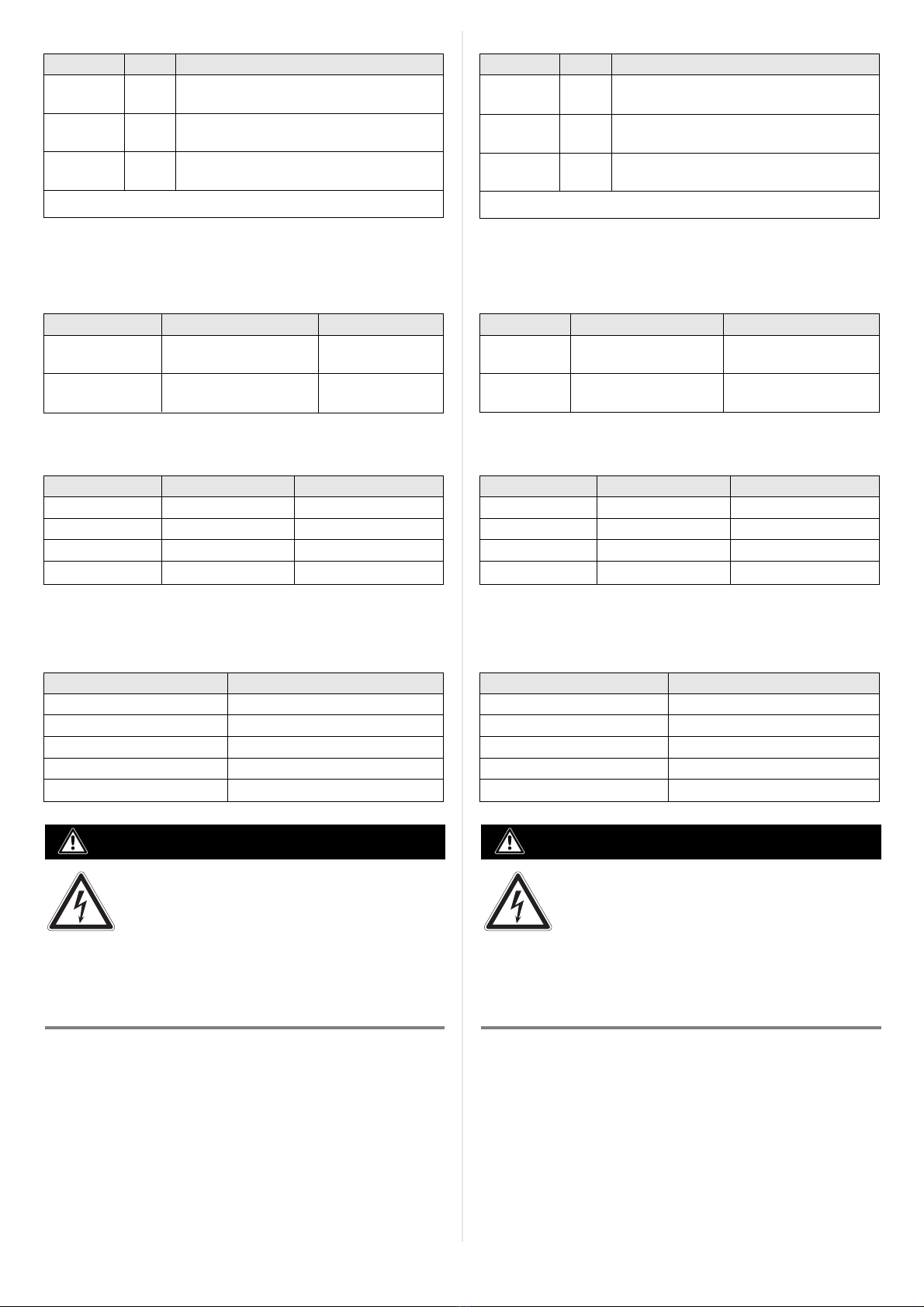
5.1 Data Interfaces
Recommended max. cable length from sensor to host:
4.2 Funktion der LEDs
LED Farbe Funktion
Power grün leuchtet, wenn die Versorgungsspannung
am CDB620 anliegt und Schalter S 1 auf „ON“
Sensor 1, 2 grün leuchtet, wenn der entsprechende (zusätzliche)
Aux In 1, 2*) Eingang des Sensors (über CMC600) schaltet
Result 1, 2 orange leuchtet, wenn der entsprechende (zusätzliche)
Aux Out 1, 2*) Ausgang des Sensors (über CMC600) schaltet
*) Voraussetzung ist das Modul CMC600
5. Elektrische Installation
5.1 Datenschnittstellen
Empfohlene max. Leitungslänge vom Sensor zum Host:
5.3 Versorgungsspannung
Der Sensor benötigt typenabhängig zur Versorgung folgende
Funktionskleinspannung gemäß IEC 60364-4-41:
4.2 LEDs
LED Color Function
Power green Lights up when the power supply is connected
to the CDB620 and switch S 1 is set to “ON“
Sensor 1, 2 green Lights up when the corresponding (additional)
Aux In 1, 2*) sensor input switches (via CMC600)
Result 1, 2 orange Lights up when the corresponding (additional)
Aux Out 1, 2*) sensor output switches (via CMC600)
*) a CMC600 module is required
Interface type Data transfer rate Distance to host
RS 232 Up to 19.2 kBd Max. 10 m (32.8 ft)
38.4 to 57.6 kBd Max. 3 m (9.84 ft)
RS 422 Max. 38.4 kBd Max. 1,200 m (3,936 ft)
Max. 57.6 kBd Max. 500 m (1,640 ft)
Schnittstellentyp Datenübertragungsrate Entfernung z. Host
RS-232 bis 19,2 kBd max. 10 m
38,4 ... 57,6 kBd max. 3 m
RS-422 max. 38,4 kBd max. 1.200 m
max. 57,6 kBd max. 500 m
Sensor Versorgungsspannung
CLV42x ... 45x / ICR85x-2 DC 10 ... 30 V
CLV62x/RFH6xx DC 10 ... 30 V
ICR84x-2 DC 15 ... 30 V
CLV480/CLV/X490 ohne Heizung DC 18 ... 30 V
CLV480/CLV/X490 mit Heizung DC 24 V +20 %/–10 %
5.2 Zusätzliche Schaltein- und Ausgänge
Die Zusatzfunktion des CMC600 unterstützt folgende Sensoren:
Sensor zusätzliche Eingänge zusätzliche Ausgänge
CLV42x ... 45x 2 –
CLV6xx / RFH6xx 2 2
ICR84x-2/ICR85x-2 – –
CLV480/ CLV/X490 – –
5.3 Supply voltage
Depending on type, the sensor requires the following functional
extra-low voltage according to IEC 60364-4-41 for power supply:
Sensor Supply voltage
CLV42x to 45x / ICR85x-2 10 to 30 V DC
CLV62x / RFH6xx 10 to 30 V DC
ICR84x-2 15 to 30 V DC
CLV480/CLV/X490 with heater 18 to 30 V DC
CLV480/CLV/X490 without heater 24 V DC +20 %/–10 %
5.2 Additional switching inputs and outputs
The CMC600 supports the following sensors:
Sensor Additional inputs Additional outputs
CLV42x to 45x 2 –
CLV6xx / RFH6xx 2 2
ICR84x-2/ICR85x-2 – –
CLV480/ CLV/X490 – –
Verletzungsgefahr durch elektrischen Strom!
Wird die Versorgungsspannung durch ein Netzgerät
erzeugt, kann mangelhafte elektrische Trennung
zwischen Eingangs- und Ausgangskreis des Netzge-
räts zu einem Stromschlag führen.
GEFAHR
¾Nur ein Netzgerät verwenden, dessen Ausgangskreis gegenüber
dem Eingangskreis eine sichere elektrische Trennung durch
Doppelisolation und Sicherheitstrafo nach IEC 742 besitzt.
5.4 Verdrahtung des CDB620
■Elektroinstallation nur durch ausgebildetes Fachpersonal
durchführen.
■Bei Arbeiten in elektrischen Anlagen die gängigen Sicherheits-
vorschriften beachten.
■Elektrische Verbindungen nur im spannungsfreien Zustand her-
stellen oder lösen.
■Um den Kurzschluss-/Überlastungschutz der abgehenden Ver-
sorgungsleitungen sicherzustellen, müssen die verwendeten
Aderquerschnitte unter Berücksichtigung der im CDB620 ein-
Risk of injuries due to electrical current!
If the supply voltage is provided by a power supply
unit, insufficient electrical insulation between input
and output circuit of the unit can cause an electric
shock.
DANGER
¾Only use a power supply unit which output circuit is safely electri-
cally isolated from the input circuit by means of double insulation
and a safety isolating transformer according to IEC 742.
5.4 Wiring the CDB620
■Electrical installation shoud only be carried out by qualified staff.
■Observe the current safety regulations when working on eletrical
systems.
■Connect or disconnect current linkages only under de-energised
conditions.
■To ensure that the outgoing supply cables are protected against
short-circuits/overload, the core cross-sections must be dimen-
sioned in accordance with the fuse installed in the CDB620. The
valid standards must be observed.