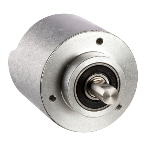
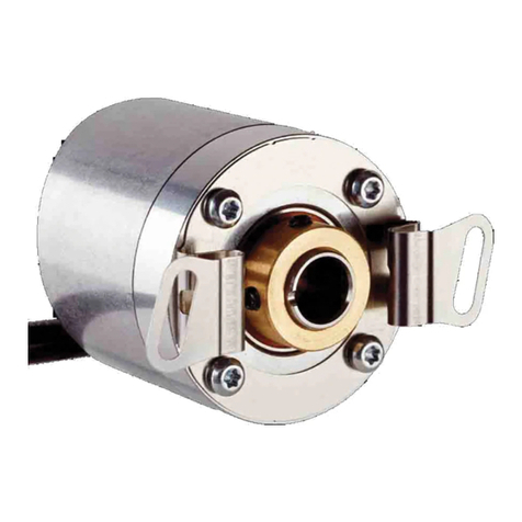
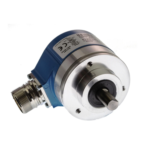
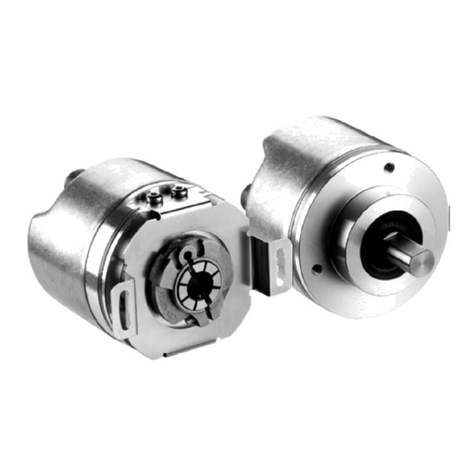
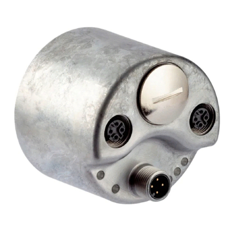
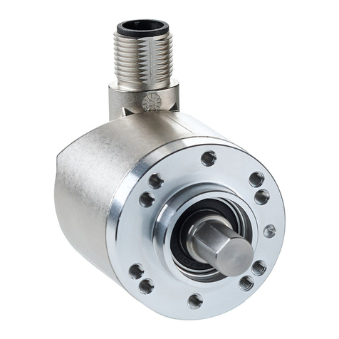
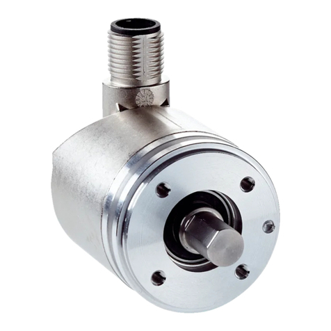
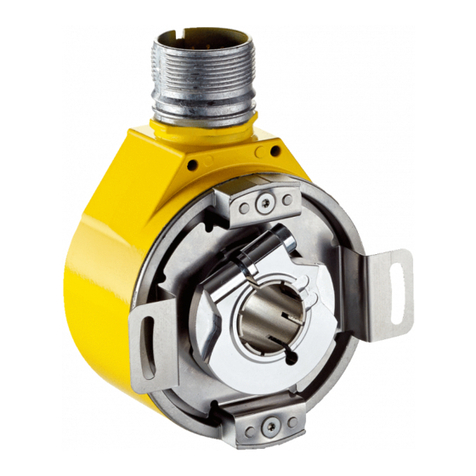
SICK ATM 60-C Series Training manual

SICK STEGMANN GmbH
Dürrheimer Str. 36
78166 Donaueschingen
Phone 0771 / 807-0
Fax 0771 / 807-100
Commissioning Instructions 915 040 002 772 March 2007
Commissioning instructions
ATM 60 absolute rotary encoder
with CANopen Interface
to communications interface DS 301 V 4.0
and device profile DSP 406 V 2.0
In work
In Arbeit

ATM60 Canopen March 2007
© by SICK STEGMANN GmbH
SICK STEGMANN GmbH claims the copyright to this documentation.
This documentation must not be modified, extended, duplicated or passed to third parties
without the agreement of SICK STEGMANN GmbH
The data in this documentation describes the product. The properties, however,
are not guaranteed.
SICK STEGMANN GmbH
Duerrheimer Straße 36
D-78166 Donaueschingen
Phone: (49) 771 / 807 – 0
Fax: (49) 771 / 807 – 100
Web: http://www.sick-stegmann.de
e-mail [email protected]
Version: March 2007
We reserve the right to make technical changes to the documentation and the products
at any time.
In work
In Arbeit

Contents
ATM60-Cxx 03/2007 1
Contents
1. Explanation of symbols ...............................................................................................................................4
2. Abbreviations used.......................................................................................................................................4
3. Safety advice .................................................................................................................................................5
4. Introduction...................................................................................................................................................6
4.1 CAN general .................................................................................................................................................6
4.2 CAN Application Layer (CAL) .......................................................................................................................6
4.3 CANopen ......................................................................................................................................................6
4.3.1 CANopen communications profile .............................................................................................................6
4.3.2 CANopen device profiles ...........................................................................................................................7
5. Communications model ...............................................................................................................................8
5.1 Process data objects (PDO) .........................................................................................................................8
5.2 Service data objects (SDOs) ........................................................................................................................9
5.3 Network management objects ....................................................................................................................10
5.3.1 Services to control the nodes ..................................................................................................................10
5.3.1.1 Start Remote Node ...............................................................................................................................10
5.3.1.2 Stop Remote Node ...............................................................................................................................10
5.3.1.3 Enter Pre-Operational...........................................................................................................................10
5.3.1.4 Reset Node...........................................................................................................................................11
5.3.1.5 Reset Communication ..........................................................................................................................11
5.3.2 Error control services...............................................................................................................................11
5.3.3 Boot-up service........................................................................................................................................11
5.4 Synchronization object (Sync object)..........................................................................................................11
5.5 Emergency object (Emcy object) ................................................................................................................11
6. Network management ................................................................................................................................12
6.1 Node monitoring .........................................................................................................................................12
6.1.1 Node guarding protocol............................................................................................................................12
6.1.2 Heartbeat protocol ...................................................................................................................................13
6.2 Synchronization...........................................................................................................................................15
7. Initialization and system boot-up..............................................................................................................15
7.1 Initialization .................................................................................................................................................15
7.2 Boot-up .......................................................................................................................................................17
7.3 Identifier allocation......................................................................................................................................17
7.3.1 Predefined Connection Set......................................................................................................................17
8. EDS file ........................................................................................................................................................18
9. Object directory of the encoder ................................................................................................................19
9.1 Object directory of the communications profiles.........................................................................................19
9.1.1 Description of the individual objects ........................................................................................................20
9.1.1.1 Object 1000 hex: device type................................................................................................................20
9.1.1.2 Object 1001 hex: error register .............................................................................................................21
9.1.1.3 Object 1003 hex: predefined error field ................................................................................................21
9.1.1.4 Object 1005 hex: COB-ID for SYNC messages ...................................................................................21
9.1.1.5 Object 1008 hex: manufacturer’s device name ....................................................................................22
9.1.1.6 Object 1009 hex: manufacturer’s hardware version .............................................................................22
9.1.1.7 Object 100A hex: manufacturer’s software version ..............................................................................22
9.1.1.8 Object 100C hex: guard time and 100D hex: lifetime factor .................................................................22
9.1.1.9 Object 1010 hex: save parameters.......................................................................................................23
9.1.1.10 Object 1011 hex: load default parameters..........................................................................................24
9.1.1.11 Object 1014 hex: COB-ID for emergency message ...........................................................................25
9.1.1.12 Object 1015 hex: inhibit time for emergency message.......................................................................26
9.1.1.13 Object 1017 hex: producer heartbeat time .........................................................................................26
9.1.1.14 Object 1800 hex: transmit PDO 1, parameter ....................................................................................26
9.1.1.15 Object 1802 hex: transmit PDO 2, parameter ....................................................................................28
In work
In Arbeit
Contents
2 ATM60-Cxx 03/2007
9.1.1.16 Object 1A00 hex: transmit PDO 1, mapping.......................................................................................28
9.1.1.17 Object 1A02 hex: transmit PDO 2, mapping.......................................................................................29
9.2 Object directory for the device profile .........................................................................................................30
9.2.1 Description of the individual objects ........................................................................................................32
9.2.1.1 Object 6000 hex: operating parameters ...............................................................................................32
9.2.1.2 Object 6001 hex: measuring steps per revolution ................................................................................32
9.2.1.3 Object 6002 hex: total number of measuring steps ..............................................................................32
9.2.1.4 Object 6003 hex: preset value ..............................................................................................................33
9.2.1.5 Object 6004 hex: position value............................................................................................................33
9.2.1.6 Object 6200 hex: cycle timer ................................................................................................................33
9.2.1.7 Object 6300 hex: cams status register .................................................................................................34
9.2.1.8 Object 6301 hex: cams, enable register ...............................................................................................34
9.2.1.9 Object 6302 hex: cams, polarity register ..............................................................................................35
9.2.1.10 Object 6310 to 6317 hex: cams 1..8, lower limit.................................................................................35
9.2.1.11 Object 6320 to 6327 hex: cams 1..8, upper limit ................................................................................35
9.2.1.12 Object 6330 to 6337 hex: cams 1..8, hysteresis.................................................................................36
9.2.1.13 Object 6400 hex: working range, status register ................................................................................36
9.2.1.14 Object 6401 hex: working range, lower limit .......................................................................................36
9.2.1.15 Object 6402 hex: working range, upper limit ......................................................................................37
9.2.1.16 Object 6500 hex: operating status ......................................................................................................37
9.2.1.17 Object 6501 hex: single-turn resolution (physical)..............................................................................37
9.2.1.18 Object 6502 hex: number of revolutions (physical).............................................................................37
9.2.1.19 Object 6503 hex: alarms.....................................................................................................................37
9.2.1.20 Object 6504 hex: alarms supported....................................................................................................38
9.2.1.21 Object 6505 hex: warnings .................................................................................................................38
9.2.1.22 Object 6506 hex: warnings supported ................................................................................................39
9.2.1.23 Object 6507 hex: profile and software version....................................................................................39
9.2.1.24 Object 6509 hex: operating time.........................................................................................................40
9.2.1.25 Object 6509 hex: offset value .............................................................................................................40
9.2.1.26 Object 650A hex: manufacturer-specific offset value .........................................................................40
9.2.1.27 Object 650B hex: serial number .........................................................................................................40
9.3 Object directory for the manufacturer-specific area....................................................................................40
9.3.1 Description of the individual objects ........................................................................................................41
9.3.1.1 Object 2000 hex: source for node ID ....................................................................................................41
In work
In Arbeit

Contents
ATM60-Cxx 03/2007 3
9.3.1.2 Object 2001 hex: node ID .....................................................................................................................41
9.3.1.3 Object 2002 hex: baud rate ..................................................................................................................41
9.3.1.4 Object 2003 hex: format for speed and acceleration............................................................................42
9.3.1.5 Object 2004 hex: speed........................................................................................................................42
9.3.1.6 Object 2005 hex: acceleration ..............................................................................................................42
9.3.1.7 Object 2006 hex: change of state .........................................................................................................43
10. Function of the cams................................................................................................................................43
11. Technical description...............................................................................................................................45
11.1 General .....................................................................................................................................................45
11.2 Features....................................................................................................................................................45
11.3 Technical data ..........................................................................................................................................46
12. Connecting the encoder...........................................................................................................................47
12.1 Setting the node ID ...................................................................................................................................47
12.2 Setting the baud rate.................................................................................................................................48
12.3 Setting the bus termination .......................................................................................................................48
12.4 Preset function..........................................................................................................................................48
12.5 Screening..................................................................................................................................................49
12.5.1 Screening rules ......................................................................................................................................49
12.6 Pin allocation.............................................................................................................................................50
12.6.1 Bus connector with PG screw fittings ....................................................................................................50
12.6.2 Bus connector with 5-pole micro circular plug connectors ....................................................................51
12.7 Status LED................................................................................................................................................51
13. Commissioning.........................................................................................................................................52
13.1 Switch on encoder ....................................................................................................................................52
13.2 Configure encoder ....................................................................................................................................53
13.2.1 Example of PDO mapping .....................................................................................................................53
13.2.2 Example of changing the object “Measuring steps per revolution” ........................................................53
13.2.3 Write all objects into EEPROM..............................................................................................................54
13.2.4 Load all objects with default values .......................................................................................................54
13.3 EDS file .....................................................................................................................................................55
14. Dimensional drawing................................................................................................................................56
15. Scope of supply ........................................................................................................................................58
16. Ordering information................................................................................................................................58
17. Notes..........................................................................................................................................................60
In work
In Arbeit

Explanation of symbols
4 ATM60-Cxx 03/2007
1. Explanation of symbols
This symbol is placed at points in the text which have to be observed in particular in order
that proper use is ensured and risks are ruled out.
This symbol indicates instructions and particularly useful information. If these are not
observed, errors may occur in the functioning of the encoder.
2. Abbreviations used
CAN Controller Area Network
CiA CAN in Automation. International association of the users and manufacturers of CAN products.
COB Communication Object. Transport unit in the CAN network (CAN message). Data is transmitted
over the network within a COB.
COB-ID COB Identifier. Unique identification of a communication object.
DS Draft Standard.
DSP Draft Standard Proposal.
ID Identifier, see COB-ID.
LSB Least Significant Bit/Byte.
MSB Most Significant Bit/Byte.
NMT Network Management. Service element of CAL implementation of initialization, configuration
and error handling in a CAN network.
PDO Process Data Object. Communication object for the rapid interchange of data.
SDO Service Data Object. Communication object for access to the object directory.
RTR Remote Transmission Request.
SYNC Synchronization Telegram.
CMS CAN Message Specification
In work
In Arbeit
Safety advice
ATM60-Cxx 03/2007 5
3. Safety advice
· Please ensure that the commissioning instructions are read before
commissioning.
· The ATM60-Cxx encodersare measuring instruments produced in accordance
with the recognized industrial regulations and meet the quality requirements of
ISO 9001.
· The installation of the encoder must be performed by specialist personnel with
knowledge of electrical engineering and precision mechanical engineering,
taking into account the relevant safety regulations.
· An ATM60-Cxx mustbe used only for the purpose appropriate to its design.
· Observe the professional safety and accident prevention regulations applicable
to your country.
· Switch off the voltage to all the devices/machines and plant involved in the
mounting.
· For satisfactory function of the devices, care must be taken to ensure good
earthing or a screen connection suitable for EMC (connecting the screen at both
ends).
· Avoid striking the shaft.
In work
In Arbeit

Introduction
6 ATM60-Cxx 03/2007
4. Introduction
4.1 CAN general
The ATM60-Cxx is an absolute encoder for use in a CAN network. The CANopen protocol, based on CAN, is
used for data transmission.
CAN was originally developed by Bosch for use in motor vehicles. The area of use of this bus system has
expanded considerably since then. Nowadays, CAN is used in mobile systems, as a communication system
within machinery or plant, in the field area of production automation, in building services engineering and in
many other sectors.
CAN has a line structure, a twisted two-wire line being used as the transmission medium. The electrical levels
are designed in accordance with ISO DIS 11898.
A main feature of CAN is the object-oriented data transmission. For this purpose, no bus participants (nodes)
are addressed, instead each variable to be transmitted is marked by a network-wide defined identifier. In
addition, in order to identify the messages, the priority of the respective variable is simultaneously defined by
the identifier during the system configuration. The allocation of priorities for the bus access method used is
necessary.
4.2 CAN Application Layer (CAL)
In order to facilitate the use of CAN in industrial applications, the “CAN in automation” (CiA) user organization
has defined a universal application interface with communications and management services for CAN
networks, the “CAN Application Layer” (CAL).
4.3 CANopen
CANopen was defined as a subset of CAL (CAN Application Layer) and, in addition, contains some
extensions specifically for industrial real-time systems. A distinction is drawn between the communications
profile and the device profile. In the communications profile (CiA DS 301), the type and manner of data
interchange between the participants is defined. In the device profile, the functionality of the participant is
defined.
4.3.1 CANopen communications profile
The communications profile of CANopen CiA DS 301 describes which properties of CAL are used in which
form. Typically, two types of communication occur in a network. Firstly, there are relatively large blocks, which
often contain configuration data, as they are known. Therefore, they are normally transmitted comparatively
rarely, and are relatively uncritical in terms of time behaviour. Secondly, there is the process data. These are
typically rather small information blocks with a high repetition rate and high requirements on uniform time
behaviour.
In work
In Arbeit

Introduction
ATM60-Cxx 03/2007 7
CANopen therefore restricts the flexibility of CAL to two data objects, “Service Data Objects” (SDO) for the
transmission of large data blocks, and “Process Data Objects” (PDO) for the real-time transmission of
process data. With the restriction to these two data types, the number of CMS objects for each device is also
reduced at the same time. This simplifies communication and helps to keep the volume of the communication
profile small.
4.3.2 CANopen device profiles
In the industrial sector, a large number of standards has led to a modular system for standard tasks, from
which one may choose relatively freely when constructing a system, without being referred to specific
manufacturers in the process. By means of device profiles, CANopen intends to expand this situation to the
sector of networked components as well. As a compromise between strict regimentation, scalability and
openness for future developments, a device profile comprises three sections:
· “Mandatory Functionality” comprises all device functions which must absolutely be present in order to
conform to the respective profile.
· “Optional Functionality” describes how optional functions are to be implemented. This means that,
although they are not prescribed, when they are present then they are defined as here.
· “Manufacturer Specific Functionality” is, finally, the section in which each manufacturer can describe his
individual functions and expansions.
For the ATM60-Cxx, the profile for encoders DSP 406 is definitive.
This profile describes a manufacturer-independent definition for encoders. It is divided into two device
classes:
· Class 1
Describes all the basic functions which the encoder must contain.
· Class 2
Contains a large number of expanded functions which must be supported by this class of encoders
(mandatory) or are optional.
In work
In Arbeit

Communications model
8 ATM60-Cxx 03/2007
5. Communications model
In CANopen, four classes of communications objects are defined:
· Process data objects (PDOs)
CAN communications objects (< 9 byte) for the transport of process data (application objects),
unconfirmed transfer of data between network participants. No protocol overhead. Content of the data
field specified by “PDO mapping”.
· Service data objects (SDOs)
Access to entries in the object directory of a device. Confirmed transfer of data of any desired length.
Two CAN identifiers per SDO object (channel). Specification of the object directory entry via index and
sub-index of the entry.
· Management objects
For tasks of network management.
· Predefined objects
For the synchronization of operations (synchronization object) and reporting device error states
(emergency object).
5.1 Process data objects (PDO)
For the ATM60-Cxx, there are two transmission PDOs, PDO 1 (tx)and PDO 2 (tx)are available for data
transmission. The content of the PDOs is specified by the respective “PDO Mapping” Object 1A00hex and
1A02hex.
The type of transmission of a PDO is specified via the sub-index 3 (transmission type) of the objects 1800hex
and 1802hex (PDO communication parameter).
The following transmission types are provided:
· Synchronous transmission
Transmission is carried out on the basis of the synchronization object.
· Asynchronous transmission
Transmission is carried out without reference to the synchronization object. The transmission is
triggered by an internal timer or by a change in a position value.
· Transmission on request
The transmission is carried out only after the request from another participant has been received.
In work
In Arbeit

Communications model
ATM60-Cxx 03/2007 9
The following objects in the object directory can be transmitted in a PDO, defined via the PDO mapping:
· Object 6004hex; position value
· Object 6300hex: status register of the CAMs
· Object 6400hex; status register of the working range
· Object 6503hex; alarms
· Object 6505hex; warnings
· Object 2004hex; speed
· Object 2005hex; acceleration
5.2 Service data objects (SDOs)
The use is predominantly the device configuration via configuration tools. Access to the object directory of the
encoder can be made via an SDO connection. All the device parameters of the encoder are stored in this
object directory at defined addresses (index and sub-index) and can be read and written via SDOs.
The ATM60-Cxx has one SDO channel, comprising:
· A transmission SDO (tx) for messages from the encoder to the master.
· A receiving SDO (rx) for messages from the master to the encoder.
Construction of an SDO message:
SDO-ID Command Index
Sub-index 4-byte data
11 bit Byte 0 Byte 1 Byte 2 Byte 3 Byte 4 Byte 5 Byte 6 Byte 7
Command
Function Telegram type Meaning
22 hex
SDO, Initiate Download
Request
Request Parameters to encoder
60 hex
SDO, Initiate Download
Response
Confirmation Parameters accepted
40 hex
SDO, Initiate Upload
Request
Request Request parameters
from encoder
43 hex
SDO, Initiate Upload
Response
Reply Transmit parameters to
master (4 bytes)
In work
In Arbeit

Communications model
10 ATM60-Cxx 03/2007
Command
Function Telegram type Meaning
4B hex
SDO, Initiate Upload
Response
Reply Transmit parameters to
master (2 bytes)
4F hex
SDO, Initiate Upload
Response
Reply Transmit parameters to
master (1 byte)
80 hex
SDO, Abort Domain
Transfer
Reply Encoder sends error
code to master
5.3 Network management objects
The following services are supported by the ATM60-Cxx.
5.3.1 Services to control the nodes
The commands are transmitted unconfirmed with the COB-ID of the NMT network object. The transmission is
built up as follows.
5.3.1.1 Start Remote Node
Master Slave
Request ®COB-ID
0
Command
1
Node ID ®Instruction
Change to operational.
5.3.1.2 Stop Remote Node
Master Slave
Request ®COB-ID
0
Command
2
Node ID ®Instruction
Change to stopped.
5.3.1.3 Enter Pre-Operational
Master Slave
Request ®COB-ID
0
Command
128
Node ID ®Instruction
In work
In Arbeit

Communications model
ATM60-Cxx 03/2007 11
5.3.1.4 Reset Node
Master Slave
Request ®COB-ID
0
Command
129
Node ID ®Instruction
All parameters in the entire object directory are set to power-on values.
5.3.1.5 Reset Communication
Master Slave
Request ®COB-ID
0
Command
130
Node ID ®Instruction
The parameters in the object directory are the communications profile are set to power-on values.
5.3.2 Error control services
· Node guarding event
· Life guarding event
· Heartbeat event.
5.3.3 Boot-up service
· Boot-up event.
5.4 Synchronization object (Sync object)
Typical applications of CANopen need a system-wide clock, with which all inputs and outputs are
synchronized. As a basis for this, CANopen provides the communication cycle.
The communication cycle is defined by specific synchronization messages, which have a very high priority.
The identifier for the synchronization message is defined in object 1005hex.
5.5 Emergency object (Emcy object)
An emergencymessage is triggered as soon as the ATM60-Cxx has detec ted an internal error.One
emergencymessage is sent for each error which has occurred. The following error messages are supported
by the emergency object:
In work
In Arbeit

Network management
12 ATM60-Cxx 03/2007
Error message Meaning
00xx Error Reset or no error
10xx General error
The meanings of the error messages are described in the communications profile of CANopen (DS 301).
6. Network management
6.1 Node monitoring
The node monitoring checks the ability of each node to communicate. In this case, a distinction is drawn
between the “node guarding protocol” and the “heartbeat protocol”.
It is possible for only one formof node monitoring to be used: either node guarding or heartbeat.
If the “producer heartbeat time (object 1017hex) = 0, then the node guarding is active. If the “producer
heartbeat time” (object 1017hex) <> 0, then the heartbeat is active.
6.1.1 Node guarding protocol
At regular intervals (node guarding time), the NMT master sends an RTR telegram to the COB-ID of the NMT
error control object. The reply from the NMT slave contains the status of the slave.
The lifetime of the slave is given by multiplying the guard time (object 100Chex) by the lifetime factor (object
100Dhex).
If no RTR telegram has been received for the period of the lifetime, then the slave signals a “remote node
error” via the NMT error control object.
In work
In Arbeit

Network management
s: Status of the encoder
4 : Stopped
5 : Operational
127 : Pre-operational
t : Toggle bit
6.1.2 Heartbeat protocol
At regular time intervals (producer heartbeat time), the “Heartbeat Producer” sends a “Heartbeat Telegram”.
This is a message with the COB-ID of the NMT error control object.
This message is received by one or more “Heartbeat Consumers”. A “Heartbeat Consumer” monitors the
receipt of “Heartbeat Telegrams” within its consumer heartbeat time. If no heartbeat telegram is received
within this time, then a heartbeat event is triggered.
Master Slave
Request COB-IDRTRInstruction
Byte 0
Confirmation COB-IDts Reply
Request COB-IDRTRInstruction
Byte 0
Confirmation COB-IDts Reply
Node Guar-
ding Event Life Guar-
ding Event
Guard Time
Life Time
ATM60-Cxx 03/2007 13
In work
In Arbeit

Network management
14 ATM60-Cxx 03/2007
Heartbeat
Producer
Heartbeat
Consumer
Request
®COB-ID Byte 0 ®Instruction
Status
Request
®COB-ID Byte 0 ®Instruction
Status
Heartbeat
Event
Status:
0 : Boot-up
4 : Stopped
5 : Operational
127 : Pre-operational
In work
In Arbeit

Initialization and system boot-up
ATM60-Cxx 03/2007 15
6.2 Synchronization
Synchronous transmission of a PDO means that the transmission has a fixed time relationship with the Sync
message. The PDO is transmitted within a defined time window, based on the synchronization message.
In the transmission window, directly after the Sync telegram, nodes send their input values and output values
priorities.
7. Initialization and system boot-up
After a change from the initializing status to the pre-operational status, the encoder sends a boot-up
7.1 Initialization
The ATM60-Cxx supports the “minimum capability device” defined in CANopen. This device type permits the
implementation of CANopen devices which have only few resources but also provide only little functionality.
Synchronus
Window Length
Sync-
Messa
g
eSync-
Messa
g
e
Transmission window Reception window
Inputs read out at the Sync command Commands are executed at the next Sync command
In work
In Arbeit

Initialization and system boot-up
16 ATM60-Cxx 03/2007
State diagram of a CANopen device with “minimum capability”:
KEY TO FIGURE
Initialization
Operational
Stopped
(12)
(8)
(8)
(7)
(6)
Pre-Operational
(11)
(10)
Power on
(11)
(11)
(10)
(10)
(7)
(6)
(6) Start_Remote_Node indication
(7) Stop_Remote_Node indication
(8) Enter_Pre-Operational_State indication
(10) Reset_Node indication
(11) Reset_Communication indication
(12) Initialization concluded, automatic transition to pre-operational
Initialization:
Initial state following application of the supply voltage. After running through the initialization, the node
changes automatically to the pre-operational state.
Pre-operational:
The SDO connections are active. The node can then be configured by making access to its object directory.
Operational:
Process values are transmitted via the PDOs.
Stopped:
No SDO or PDO connections are active. The node can be brought into the pre-operational or operational
state via NMT commands.
In work
In Arbeit

Initialization and system boot-up
ATM60-Cxx 03/2007 17
7.2 Boot-up
The boot-up message signals the transition of an NMT slave from the “initializing” state to the “pre-
operational” state. The boot-up message uses the COB-ID of the NMT error control object.
Master Slave
Instruction ¬COB-ID Status = 0 ¬Request
Status = 0 signals that this is a boot-up message.
7.3 Identifier allocation
The identifier allocation is required in each ATM60-Cxx for:
· SDOs
· PDOs
· Synchronization object
· Emergency object
· Network management object.
For simple management of the identifiers, CANopen uses the “predefined connection set”. Here, the COB
identifiers are allocated in accordance with the node ID (module ID) and the function code.
7.3.1 Predefined Connection Set
The 11-bit identifier is composed here of a 4-bit function code and 7-bit node ID (module ID).
Bit 10 Bit 9 Bit 8 Bit 7 Bit 6 Bit 5 Bit 4 Bit 3 Bit 2 Bit 1 Bit 0
Function code Node ID (module ID)
Identifier allocation is static and depends on the node ID (module ID). This permits rapid configuration of
simple networks.
The node ID in the ATM60-Cxx can be set via a six-pole DIP switch. This means that, for the ATM
60-Cxx, a node ID in the range from 1 to 63 can be set via the DIP switches. Bit 6 of the node
ID is therefore always 0.
Identifier allocation for broadcast objects:
In work
In Arbeit

EDS file
18 ATM60-Cxx 03/2007
Object Function code
(binary)
COB-ID
NMT Network Object 0000 0
SYNC 0001 128
Identifier allocation for communications objects:
Object Function code
(binary)
COB-ID
EMERGENCY 0001 129-255
PDO 1 (tx) 0011 385-511
PDO 1 (rx) 0100 513-639
PDO 2 (tx) 0101 641-767
PDO 2 (rx) 0110 769-895
SDO (tx) 1011 1409-1535
SDO (rx) 1100 1537-1663
NMT Error Control 1110 1793-1919
8. EDS file
The EDS file is the electronic description of the object directory of a device. The description of the object
directory is required for the configuration and operation of the device.
The EDS file is read in by a configuration tool. Using the entries in the EDS file, the configuration tool
provides the user with all the available objects in this device.
As a result, a device can be configured easily without any prior knowledge of its object directory.
In work
In Arbeit
This manual suits for next models
3
Table of contents
Other SICK Media Converter manuals

SICK
SICK KH53 Operating instructions

SICK
SICK AFS60 PROFINET User manual

SICK
SICK AFS/AFM60 PROFINET User manual

SICK
SICK MRA-G Series User manual

SICK
SICK EtherNet/IP AFS60 User manual

SICK
SICK ATM60 SSI User manual

SICK
SICK AHS36 CANopen User manual

SICK
SICK DLS40 User manual

SICK
SICK DFS60S Pro User manual

SICK
SICK A3M60 Advanced User manual

SICK
SICK MAS User manual

SICK
SICK AFS60 PROFINET User manual

SICK
SICK DGS66 User manual

SICK
SICK AHS36 IO-Link User manual

SICK
SICK MAX30N User manual

SICK
SICK AHS/AHM36 SAE J1939 User manual

SICK
SICK AFS60S Pro User manual

SICK
SICK DBS36 Core User manual

SICK
SICK AFS60 S01 User manual

SICK
SICK EtherCAT AFS60 User manual