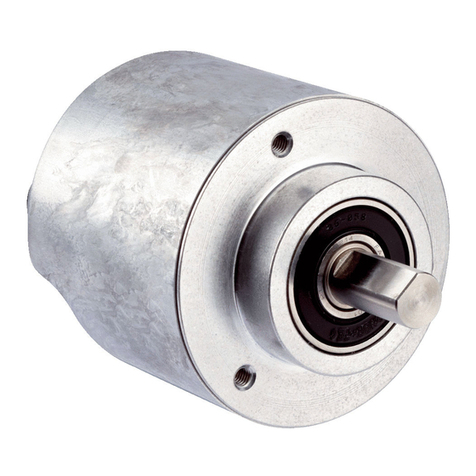
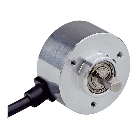
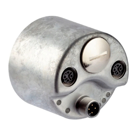
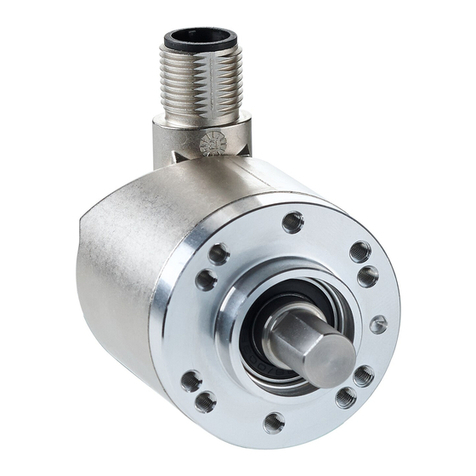
SICK AHS/AHM36 SAE J1939 User manual

OPERATING INSTRUCTIONS
AHS/AHM36 SAE J1939
AHS/AHM36 SAE J1939 Inox
Absolute encoder

Described product
AHS/AHM36 SAE J1939
AHS/AHM36 SAE J1939 Inox
Manufacturer
SICK AG
Erwin-Sick-Str. 1
79183 Waldkirch
Germany
Legal information
This work is protected by copyright. Any rights derived from the copyright shall be
reserved for SICK AG. Reproduction of this document or parts of this document is
only permissible within the limits of the legal determination of Copyright Law. Any modi‐
fication, abridgment or translation of this document is prohibited without the express
written permission of SICK AG.
The trademarks stated in this document are the property of their respective owner.
© SICK AG. All rights reserved.
Original document
This document is an original document of SICK AG.
2O P E R A T I N G I N S T R U C T I O N S | AHS/AHM36 SAE J1939
AHS/AHM36 SAE J1939 Inox
8027379/2022-01-21 | SICK
Subject to change without notice

Contents
1 About this document........................................................................ 5
1.1 Scope......................................................................................................... 5
1.2 Function of this document....................................................................... 5
1.3 Target group.............................................................................................. 5
1.4 Information depth..................................................................................... 5
1.5 Symbols used............................................................................................ 6
2 Safety information............................................................................ 7
2.1 General safety notes and protective measures...................................... 7
2.2 Intended use............................................................................................. 7
2.3 Authorized personnel................................................................................ 8
2.4 Environmental protection......................................................................... 8
3 Product description........................................................................... 9
3.1 Specific features....................................................................................... 9
3.2 Operating principle of the encoder.......................................................... 10
3.2.1 Scaleable resolution................................................................ 10
3.2.2 Preset function......................................................................... 11
3.3 Controls and status indicators................................................................. 11
4 Integration in a SAE J1939 network............................................... 12
4.1 Parameterizable functions....................................................................... 12
4.1.1 Scaling parameters................................................................. 12
4.1.2 Preset function......................................................................... 12
4.1.3 Speed measurement............................................................... 13
5 SAE J1939 interface......................................................................... 14
5.1 Protocol data unit..................................................................................... 14
5.2 Parameter group number......................................................................... 15
5.3 Device name and address....................................................................... 15
5.4 Process data (transmit PGNs)................................................................. 16
5.5 Sensor configuration................................................................................ 17
5.5.1 Message ID.............................................................................. 17
5.5.2 Parameter index....................................................................... 18
5.5.3 Parameter length..................................................................... 18
5.5.4 Error code................................................................................. 19
5.5.5 Parameter value...................................................................... 19
5.5.6 Examples of parameter changes............................................ 22
6 Commissioning.................................................................................. 23
6.1 Electrical installation................................................................................ 23
6.1.1 Connecting the AHS/AHM36 SAE J1939 and AHS/AHM36
SAE J1939 Inox........................................................................ 23
6.1.2 Delivery state........................................................................... 24
6.1.3 Checks before initial commissioning...................................... 24
CONTENTS
8027379/2022-01-21 | SICK O P E R A T I N G I N S T R U C T I O N S | AHS/AHM36 SAE J1939
AHS/AHM36 SAE J1939 Inox 3
Subject to change without notice
7 Fault diagnosis................................................................................... 25
7.1 In the event of faults or errors................................................................. 25
7.2 Support...................................................................................................... 25
7.3 Error and status indications on the LED................................................. 25
7.3.1 Meaning of LED indicators...................................................... 25
8 Annex.................................................................................................. 26
8.1 Conformities and certificates................................................................... 26
8.1.1 Compliance with EU directives................................................ 26
8.1.2 Compliance with UK statutory instruments........................... 26
CONTENTS
4O P E R A T I N G I N S T R U C T I O N S | AHS/AHM36 SAE J1939
AHS/AHM36 SAE J1939 Inox
8027379/2022-01-21 | SICK
Subject to change without notice

1 About this document
Please read this chapter carefully before working with this documentation and the AHS/
AHM36 SAE J1939 und AHS/AHM36 SAE J1939 Inox Absolute encoder.
1.1 Scope
NOTE
These operating instructions apply to the absolute encoders AHS/AHM36 SAE J1939
and AHS/AHM36 SAE J1939 Inox with the following type designations:
•Singleturn Encoder Basic = AHS36B-xxJx004096
•Multiturn Encoder Basic = AHM36B-xxJx012x12
•Singleturn Encoder Advanced = AHS36A-xxJx016384
•Multiturn Encoder Advanced = AHM36A-xxJx014x12
•Singleturn Encoder Inox = AHS36I-xxJx016384
•Multiturn Encoder Inox = AHM36I-xxJx014x12
1.2 Function of this document
These operating instructions are designed to address the technical personnel of the
machine manufacturer or the machine operator in regards to correct configuration,
electrical installation, commissioning, operation and maintenance of the AHS/AHM36
SAE J1939 und AHS/AHM36 SAE J1939 Inox Absolute encoder.
1.3 Target group
The operating instructions are addressed at the planners, developers and operators of
systems in which one or more AHS/AHM36 SAE J1939 und AHS/AHM36 SAE J1939
Inox Absolute encoder are to be integrated. They also address people who initialize the
use of the AHS/AHM36 SAE J1939 und AHS/AHM36 SAE J1939 Inox or who are in
charge of servicing and maintaining the device.
These instructions are written for trained persons who are responsible for the installa‐
tion, mounting and operation of the AHS/AHM36 SAE J1939 und AHS/AHM36 SAE
J1939 Inox in an industrial environment.
1.4 Information depth
These operating instructions contain information on the AHS/AHM36 SAE J1939 und
AHS/AHM36 SAE J1939 Inox Absolute encoder on the following subjects:
•product features
•electrical installation
•commissioning and configuration
•fault diagnosis and troubleshooting
•conformity
These operating instructions do not contain any information on the mounting of the
AHS/AHM36 SAE J1939 und AHS/AHM36 SAE J1939 Inox. You will find this informa‐
tion in the mounting instructions included with the device.
They also do not contain any information on technical specifications, dimensional draw‐
ings, ordering information or accessories. You will find this information in the product
information for the AHS/AHM36 SAE J1939 und AHS/AHM36 SAE J1939 Inox.
ABOUT THIS DOCUMENT 1
8027379/2022-01-21 | SICK O P E R A T I N G I N S T R U C T I O N S | AHS/AHM36 SAE J1939
AHS/AHM36 SAE J1939 Inox 5
Subject to change without notice

Planning and using measurement systems such as the AHS/AHM36 SAE J1939 und
AHS/AHM36 SAE J1939 Inox also requires specific technical skills beyond the informa‐
tion in the operating instructions and mounting instructions. The information required to
acquire these specific skills is not contained in this document.
When operating the AHS/AHM36 SAE J1939 und AHS/AHM36 SAE J1939 Inox, the
national, local and statutory rules and regulations must be observed.
1.5 Symbols used
NOTE
Refer to notes for special features of the device.
LED symbols describe the state of a diagnostics LED. Examples:
OThe LED is illuminated constantly.
ôFõ The LED flashes evenly.
ôKõ The LED flashes with a short duty cycle.
oThe LED is off.
bTake action …
Instructions for taking action are shown by an arrow. Read carefully and follow the
instructions for action.
CAUTION
Warning!
A warning notice indicates an actual or potential risk or health hazard. They are
designed to help you to prevent accidents.
Read carefully and follow the warning notices.
1 ABOUT THIS DOCUMENT
6O P E R A T I N G I N S T R U C T I O N S | AHS/AHM36 SAE J1939
AHS/AHM36 SAE J1939 Inox
8027379/2022-01-21 | SICK
Subject to change without notice

2 Safety information
This chapter deals with your own safety and the safety of the equipment operators.
bPlease read this chapter carefully before working with the AHS/AHM36 SAE J1939
und AHS/AHM36 SAE J1939 Inox or with the machine or system in which the
AHS/AHM36 SAE J1939 und AHS/AHM36 SAE J1939 Inox is used.
2.1 General safety notes and protective measures
CAUTION
Please observe the following procedures in order to ensure the correct and safe use of
the AHS/AHM36 SAE J1939 und AHS/AHM36 SAE J1939 Inox!
The encoder is to be installed and maintained by trained and qualified personnel
with knowledge of electronics, precision mechanics and control system programming.
It is necessary to comply with the related standards covering the technical safety
stipulations.
All safety regulations are to be met by all persons who are installing, operating or
maintaining the device:
•The operating instructions must always be available and must always be followed.
•Unqualified personnel are not allowed to be present in the vicinity of the system
during installation and maintenance.
•The system is to be installed in accordance with the applicable safety stipulations
and the mounting instructions.
•All work safety regulations of the applicable countries are to be followed during
installation.
•Failure to follow all applicable health and work safety regulations may result in
injury or damage to the system.
•The current and voltage sources in the encoder are designed in accordance with
all applicable technical regulations.
2.2 Intended use
The AHS/AHM36 SAE J1939 und AHS/AHM36 SAE J1939 Inox Absolute encoder is
a measuring device that is manufactured in accordance with recognized industrial
regulations and meets the quality requirements as per ISO 9001:2008 as well as those
of an environment management system as per ISO 14001:2009.
An encoder is a device for mounting that cannot be used independent of its foreseen
function. For this reason an encoder is not equipped with immediate safe devices.
Measures for the safety of persons and systems must be provided by the constructor of
the system as per statutory regulations.
Due to its design, the AHS/AHM36 SAE J1939 and AHS/AHM36 SAE J1939 Inox can
only be operated within an SAE J1939 network. It is necessary to comply with the SAE
J1939 specifications and guidelines for setting up a SAE J1939 network.
In case of any other usage or modifications to the AHS/AHM36 SAE J1939 und AHS/
AHM36 SAE J1939 Inox, e.g. opening the housing during mounting and electrical
installation, or in case of modifications to the SICK software, any claims against SICK
AG under warranty will be rendered void.
SAFETY INFORMATION 2
8027379/2022-01-21 | SICK O P E R A T I N G I N S T R U C T I O N S | AHS/AHM36 SAE J1939
AHS/AHM36 SAE J1939 Inox 7
Subject to change without notice

2.3 Authorized personnel
The AHS/AHM36 SAE J1939 und AHS/AHM36 SAE J1939 Inox Absolute encoder must
only be installed, commissioned and serviced by authorized personnel.
NOTE
Repairs to the AHS/AHM36 SAE J1939 und AHS/AHM36 SAE J1939 Inox are only
allowed to be undertaken by trained and authorized service personnel from SICK AG.
The following qualifications are necessary for the various tasks:
Table 1: Authorized personnel
Activity Qualification
Mounting •Basic technical training
•Knowledge of the current safety regulations in the
workplace
Electrical installation and replace‐
ment
•Practical electrical training
•Knowledge of current electrical safety regulations
•Knowledge on the use and operation of devices in
the related application (e.g. industrial robots, storage
and conveyor technology)
Commissioning, operation and con‐
figuration
•Knowledge on the current safety regulations and the
use and operation of devices in the related applica‐
tion
•Knowledge of automation systems
•Knowledge of SAE J1939
•Knowledge of automation software
2.4 Environmental protection
Please note the following information on disposal.
Table 2: Disposal of the assemblies
Assembly Material Disposal
Packaging Cardboard Waste paper
Shaft Stainless steel Scrap metal
Flange Aluminium / Stainless steel Scrap metal
Housing Aluminium die cast with Zinc
nickel coating / stainless steel
Scrap metal
Electronic assemblies Various Electronic waste
2 SAFETY INFORMATION
8O P E R A T I N G I N S T R U C T I O N S | AHS/AHM36 SAE J1939
AHS/AHM36 SAE J1939 Inox
8027379/2022-01-21 | SICK
Subject to change without notice

3 Product description
This chapter provides information on the special features and properties of the Abso‐
lute encoder AHS/AHM36 SAE J1939 und AHS/AHM36 SAE J1939 Inox. It describes
the construction and the operating principle of the device.
bPlease read this chapter before mounting, installing and commissioning the
device.
3.1 Specific features
With male con‐
nector
With cable
Table 3: Special features of the encoder variants
Features Singleturn
Encoder
Basic
Multiturn
Encoder
Basic
Singleturn
Encoder
Advanced
Multiturn
Encoder
Advanced
Singleturn
Encoder
Inox
Multiturn
Encoder
Inox
SAE J1939
interface
C C C C C C
12 bit
singleturn resolution
(1 to 4,096 steps)
C C - - - -
14 bit
singleturn resolution
(1 to 16,384 steps)
- - C C C C
12 bit
multiturn resolution
(1 to 4,096 revolu‐
tions)
-C-C-C
24 bit
total resolution
-C- - - -
26 bit
total resolution
- - - C-C
Absolute encoder in
36 mm design
C C C C C C
Non-contact,
magnetic scanning
C C C C C C
Flexible
Cable connection/
M12 male connector
C C C C C C
Numerous
mechanical
adaptation possibili‐
ties
C C C C C C
Compact design C C C C C C
PRODUCT DESCRIPTION 3
8027379/2022-01-21 | SICK O P E R A T I N G I N S T R U C T I O N S | AHS/AHM36 SAE J1939
AHS/AHM36 SAE J1939 Inox 9
Subject to change without notice

Features Singleturn
Encoder
Basic
Multiturn
Encoder
Basic
Singleturn
Encoder
Advanced
Multiturn
Encoder
Advanced
Singleturn
Encoder
Inox
Multiturn
Encoder
Inox
Face mount flange,
servo flange, blind hol‐
low shaft
C C C C C C
Stainless steel version - - - - C C
IP69K enclosure rat‐
ing
- - - - C C
3.2 Operating principle of the encoder
The sensing system in the AHS/AHM36 SAE J1939 und AHS/AHM36 SAE J1939
Inox AHS/AHM36 SAE J1939 und AHS/AHM36 SAE J1939 Inox is based on absolute
acquisition of revolutions without an external voltage supply or battery. As a conse‐
quence the encoder can immediately output its absolute position again after switching
off and switching back on.
The AHS/AHM36 SAE J1939 und AHS/AHM36 SAE J1939 Inox acquires the position of
rotating axes and outputs the position in the form of a unique digital numeric value. The
highest reliability is achieved by means of electrosensitive, magnetic scanning.
The AHS36 is a singleturn encoder.
Singleturn encoders are used if absolute acquisition of the rotation of a shaft is
required.
The AHM36 is a multiturn encoder.
Multiturn encoders are used if more than one shaft revolution must be acquired abso‐
lutely.
3.2.1 Scaleable resolution
The resolution per revolution and the total resolution can be scaled and adapted to the
related application.
The resolution per revolution can be scaled in integers from 1 … 4,096 (Basic) or from
1 … 16,384 (Advanced / Inox).
The total resolution of the AHS/AHM36 SAE J1939 und AHS/AHM36 SAE J1939 Inox
must be 2ⁿ times the resolution per revolution. This restriction is not relevant if the
round axis functionality is activated.
3 PRODUCT DESCRIPTION
10 O P E R A T I N G I N S T R U C T I O N S | AHS/AHM36 SAE J1939
AHS/AHM36 SAE J1939 Inox
8027379/2022-01-21 | SICK
Subject to change without notice

3.2.2 Preset function
The position value for an encoder can be set with the aid of a preset value. I.e. the
encoder can be set to any position within the measuring range. In this way, e.g., the
encoder’s zero position can be adjusted to the machine’s zero point.
On switching off the encoder, the offset, the difference between the real position value
and the value defined by the preset, is saved. On switching back on the new preset
value is formed from the new real position value and the offset. Even if the position of
encoder changes while it is switched off, this procedure ensures the correct position
value is still output.
1on switching off
2on switching back on
3.3 Controls and status indicators
The AHS/AHM36 SAE J1939 und AHS/AHM36 SAE J1939 Inox Absolute encoder has
one status LED.
LED
Figure 1: Position of the LED
The LED is multicolored. see table 16, page 25 shows the meaning of the signals.
PRODUCT DESCRIPTION 3
8027379/2022-01-21 | SICK O P E R A T I N G I N S T R U C T I O N S | AHS/AHM36 SAE J1939
AHS/AHM36 SAE J1939 Inox 11
Subject to change without notice

4 Integration in a SAE J1939 network
4.1 Parameterizable functions
The AHS/AHM36 SAE J1939 and AHS/AHM36 SAE J1939 Inox are configured by
means of various parameters.
The most important parameters for parameterizing the functions are shown below.
CAUTION
When parameterizing the encoder, make sure that there are no persons in the hazard‐
ous area of a system!
All parameter changes directly affect the operation of the encoder. The position value
can therefore change during parameterization, e.g., if a preset is executed or the scaling
is changed. This could cause an unexpected movement that could endanger people or
damage the system or other objects.
4.1.1 Scaling parameters
Scaling
This parameter enables the resolution per revolution or the total resolution to be
scaled.
Code sequence
The code sequence determines in which direction of rotation the position value
increases when viewed in the direction of the shaft.
•Clockwise (cw) = increasing position value when the shaft rotates clockwise
•Counterclockwise (ccw) = increasing position value when the shaft rotates coun‐
terclockwise
The resolution of the AHS/AHM36 SAE J1939 Basic is max. 4,096 steps per revolution.
The resolution is scalable in whole number increments from 1 ... 4,096.
The resolution of the AHS/AHM36 SAE J1939 Advanced / Inox is max. 16,384 steps
per revolution. The resolution is scalable in whole number increments from 1 ...
16,384.
The total resolution, i.e., the measuring range of the AHM36 SAE J1939 Basic, is max.
16,777,216 steps. The total resolution of the AHM36 SAE J1939 Advanced / Inox is
max. 67,108,864 steps.
The total resolution must be 2ⁿ times the resolution per revolution.
Table 4: Examples for total resolution
Resolution per revolution n Total resolution
1,000 3 8,000
8,179 5 261,728
2,048 11 4,194,304
4.1.2 Preset function
The preset function can be used to set the position value of the encoder. I. e. the
encoder can be set to any position within the measuring range.
NOTE
The preset value must be within the configured measuring range.
4 INTEGRATION IN A SAE J1939 NETWORK
12 O P E R A T I N G I N S T R U C T I O N S | AHS/AHM36 SAE J1939
AHS/AHM36 SAE J1939 Inox
8027379/2022-01-21 | SICK
Subject to change without notice

CAUTION
Before triggering the preset function, check whether there is any danger from the
machine or system in which the encoder is integrated!
The preset function leads to a change of the position value output by the encoder.
This could cause an unexpected movement that could endanger people or damage the
system or other objects.
4.1.3 Speed measurement
Possible units are:
•cps = counts per second
•cp10 ms = counts per 10 ms
•cp100 ms = counts per 100 ms
•rpm = revolutions per minute
•rps = revolutions per second
The factory setting is rpm.
NOTE
The unit of speed should be selected so that the maximum speed value occurring in the
application can be represented in the selected PGN. (TxPGN1 only 2 bytes for speed)
INTEGRATION IN A SAE J1939 NETWORK 4
8027379/2022-01-21 | SICK O P E R A T I N G I N S T R U C T I O N S | AHS/AHM36 SAE J1939
AHS/AHM36 SAE J1939 Inox 13
Subject to change without notice
5 SAE J1939 interface
This section contains general information about using the CAN protocol with extended
29-bit CAN identifiers. This 29-bit CAN frame format is the only format allowed for
J1939 CAN messages. Standard 11-bit CAN frames can, however, also be used in the
network.
5.1 Protocol data unit
The protocol data unit (PDU) provides a framework for organizing the information essen‐
tial to each CAN data frame sent. The extended CAN data frame used for the SAE
J1939 protocol is divided into seven fields. The 29-bit identifier is composed of six
fields.
J1939 PDU
P R
D
PPF PS SA Data Field
. . . . .
Bits 3 1 1 8 8 8 0 ... 64
Figure 2: Definition of the extended CAN data frame (29-bit identifier + data field)
Components of the 29-bit identifier
P – Priority
These three bits are used to optimize message latency for transmission (3 bits).
R – Reserved
Value is always 0 (1 bit).
DP – Data Page
Value is always 0 (1 bit).
PF – PDU Format
This field is used to specify the parameter group number (PGN). Parameter group
numbers identify or label information that require one or more CAN data frames to
transmit them. The PDU format is the mid-byte of the parameter group number. see
figure 3, page 15
PS – PDU Specific
This field depends on the value of PDU Format, and contains either a destination
address or a group extension, depending on PDU Format. If the value of the PDU
Format field is less than 240, the PDU Specific field contains a destination address.
If the value of the PDU Format field is between 240 and 255, the PDU Specific field
contains a group extension value. PDU2 format messages are global messages.
Table 5: PDU definition
PDU Format field PDU Specific field
PDU1 format 0 - 239 Destination address
PDU2 format 240 - 255 Group extension
Specific Destination Address (DA)
This field defines the specific address to which the message is being sent. All other
destinations should ignore this message. In the case of the global destination address
(255), all devices are required to listen and respond as message recipients.
5 SAE J1939 INTERFACE
14 O P E R A T I N G I N S T R U C T I O N S | AHS/AHM36 SAE J1939
AHS/AHM36 SAE J1939 Inox
8027379/2022-01-21 | SICK
Subject to change without notice
Group Extension (GE)
The Group Extension field provides 4,069 parameter groups per page.
Source Address (SA)
There should only be one device on the network with a given source address. The
Source Address field therefore ensures the CAN identifier is unique, as required by CAN.
Data field
The J1939 protocol data unit (PDU) can contain up to 8 bytes, as per the definition of
the CAN data frame.
5.2 Parameter group number
The PGN uniquely identifies the parameter group (PG) that is being transmitted in the
message. Every PG (grouping of specific parameters) has its own specific definition
comprising the assignment of each parameter within an 8-byte data field (size in bytes,
location of the LSB), and the transmission rate and priority of the message.
3 Bit
Priority
1 Bit
Reserved
1 Bit
Data Page
8 Bit
PDU Format
8 Bit
PDU Specific
8 Bit
Source
Adress
1 Bit
Reserved
1 Bit
Data Page
8 Bit
PDU Format
8 Bit
PDU Specific
29 Bit
CAN ID
Figure 3: Parameter group number
Generally speaking, a distinction can be made between messages that are exchanged
between two nodes by direct addressing (PDU format 1), and broadcast messages that
are send to all nodes on the bus (PDU format 2).
The PDU format values 00h to EFh are reserved for point-to-point messages; the PGN
also contains the destination address. Broadcast messages are sent with PDU format
values from F0h to FFh. The Group Extension field increases the number of available
broadcast messages. The encoder uses broadcast messages with PDU format 2 to
send the process data. Direct addressing in PDU format 1 using the Proprietary A PGN
is supported for configuration.
5.3 Device name and address
With the factory settings, the encoder starts with the address 224d (E0h). Dynamic
address allocation is supported. At startup the encoder sends a suitable address claim
telegram with the address used. This message contains the 64-bit device name by
means of which the sensor can be uniquely identified. The priority on the bus is also
determined based on the name.
The 64-bit device name contains the following fields:
SAE J1939 INTERFACE 5
8027379/2022-01-21 | SICK O P E R A T I N G I N S T R U C T I O N S | AHS/AHM36 SAE J1939
AHS/AHM36 SAE J1939 Inox 15
Subject to change without notice
•Arbitrary Address Capable, support for dynamic address allocation (1 bit)
•Industry Group (3 bits)
•Vehicle System Instance (4 bits)
•Vehicle System (7 bits)
•Function (8 bits)
•Function Instance (5 bits)
•ECU Instance (3 bits)
•Manufacturer Code (11 bits)
•Identity Number (21 bits)
The Manufacturer Code represents the manufacturer identification SICK AG (value
885 decimal).
The Identity Number corresponds to the J1939 serial number of the encoder.
The following fields of the device name are predefined as factory defaults:
•Manufacturer Code: 885 (SICK AG)
•Identity Number: J1939 serial number of the sensor
•Industry Group: 0
•Vehicle System: 0
•Function: 142 (Rotation Sensor)
The remaining ranges can be modified by the user via the configuration protocol (see
"Sensor configuration").
5.4 Process data (transmit PGNs)
The device supports 3 different parameter groups (TxPGNs):
•TxPGN1 65504 (FFE0h): Position (4 bytes), speed (2 bytes), diagnostics (2 bytes)
•TxPGN2 65505 (FFE1h): Position (4 bytes), temperature (2 bytes), diagnostics
(2 bytes)
•TxPGN3 65506 (FFE2h): Speed (4 bytes), temperature (2 bytes), diagnostics
(2 bytes)
Activation/deactivation of sending, the cycle time, and the priority of messages can be
set using configuration messages. By default, TxPGNs 65504 (FFE0) are activated with
a cycle time of 10 ms.
5 SAE J1939 INTERFACE
16 O P E R A T I N G I N S T R U C T I O N S | AHS/AHM36 SAE J1939
AHS/AHM36 SAE J1939 Inox
8027379/2022-01-21 | SICK
Subject to change without notice

Table 6: Overview of transmit PGNs
PGN FFE0 (default) FFE1 FFE2
Byte 1 Position Position Speed (32 bit)
Byte 2 Position Position Speed (32 bit)
Byte 3 Position Position Speed (32 bit)
Byte 4 Position Position Speed (32 bit)
Byte 5 Speed (16 bit) Temperature Temperature
Byte 6 Speed (16 bit) Temperature Temperature
Byte 7 Diagnosis Diagnosis Diagnosis
Byte 8 Diagnosis Diagnosis Diagnosis
5.5 Sensor configuration
Proprietary A PGN 61184 (point-to-point) is used to configure the sensor. The structure
of the data part of the message is as follows:
Table 7: Structure of the Data Part of the Message
Byte 1 Byte 2 Byte 3 Byte 4 Byte 5 - 8
Message ID see
"Message ID",
page 17
Parameter index
see "Parameter
index", page 18
Parameter length
see "Parameter
length", page 18
Error code see
"Error code",
page 19
Parameter value
see "Parameter
value", page 19
5.5.1 Message ID
The relevant action is defined via the message ID:
If the parameter is one, a read command was requested, if however the parameter is
two, the received data is written to the encoder.
Table 8: Message ID
Value Meaning
0 Parameter data
1 Read parameters
2 Write the parameters
Read parameter
The counterpart CA reads a parameter from the encoder CA.
Request from counterpart CA
If the counterpart wants to read a parameter from the encoder, the message ID must
have the value one. In this case the counterpart CA sends the following message to the
encoder, e.g., read counting direction.
29-bit identifier Data field
Pri‐
orit
y
R DP PD
U
DestAdr
Enc-
Adr.
SourAdr
Coun‐
ter- part
Adr.
Mes.ID Param-
Idx
Param-
Lngt
Err-
code
D5 D6 D7 D8
70023
9
1 129 1 0 0 0 0 0
Response from encoder CA
A successful encoder response to the counterpart CA read request shows, for example,
that the actual counting direction is cw (clockwise).
SAE J1939 INTERFACE 5
8027379/2022-01-21 | SICK O P E R A T I N G I N S T R U C T I O N S | AHS/AHM36 SAE J1939
AHS/AHM36 SAE J1939 Inox 17
Subject to change without notice
29-bit identifier Data field
Pri‐
orit
y
R DP PD
U
Coun‐
ter-part
Adr
SourAdr
Enc Adr.
Mes.ID Param-
Idx
Param-
Lngt
Err-
code
D5 D6 D7 D8
70023
9
0 129 1 0 0 0 0 0
Write parameter
The counterpart CA changes a parameter within the encoder CA.
Request from counterpart CA
If the counterpart wants to change the encoder parameters, the message ID must have
the value two. In this case the counterpart CA sends the following message to the
encoder, for example to change the counting direction to ccw (counterclockwise).
29-bit identifier Data field
Pri‐
orit
y
R DP PD
U
DestAdr
Enc-
Adr.
SourAdr
Coun‐
ter- part
Adr.
Mes.ID Param-
Idx
Param-
Lngt
Err-
code
D5 D6 D7 D8
70023
9
2 129 1 0 1 0 0 0
Response from the encoder CA
A successful encoder response to the counterpart CA write request shows, for example,
that the actual counting direction was set to ccw.
29-bit identifier Data field
Pri‐
orit
y
R DP PD
U
DestAdr
Coun‐
ter- part
Adr
SourAdr
Enc-Adr
Mes.ID Param-
Idx
Param-
Lngt
Err-
code
D5 D6 D7 D8
70023
9
0 129 1 0 1 0 0 0
A failed encoder response to a counterpart CA write request shows, for example, that
parameter index 136 is not supported, as indicated by error code 01.
29-bit identifier Data field
Pri‐
orit
y
R DP PD
U
DestAdr
Coun‐
ter- part
Adr
SourAdr
Enc-Adr
Mes.ID Param-
Idx
Param-
Lngt
Err-
code
D5 D6 D7 D8
70023
9
0 136 1 1 1 0 0 0
5.5.2 Parameter index
The parameter index defines which parameter is addressed, e.g., index 129 as the
parameter for the counting direction. All parameters are listed in the Parameter value
section see "Parameter value", page 19.
5.5.3 Parameter length
The parameter length specifies the number of parameter value data. All parameters are
listed in the Parameter value section see "Parameter value", page 19.
5 SAE J1939 INTERFACE
18 O P E R A T I N G I N S T R U C T I O N S | AHS/AHM36 SAE J1939
AHS/AHM36 SAE J1939 Inox
8027379/2022-01-21 | SICK
Subject to change without notice
5.5.4 Error code
The error code is only relevant if the relevant telegram is sent by the encoder (message
ID is 0). The error code signals the success of the write command within the response
message. The remote CA receives a response to a write command and also to a
read command. If the value within the error code segment is not zero, the previous
command was not executed successfully.
Table 9: Error code
Value (hex) Meaning
00 Successful
01 Parameter not available
02 Parameter length incorrect
03 Parameter value too high/low
04 Parameter value not supported
05 An attempt was made to read a "write-only" parameter
06 An attempt was made to write a "read-only" parameter
07 Message ID is not supported
FF Unknown error
5.5.5 Parameter value
The parameter value contains the parameter user data. The data appears left-aligned and little endian.
The encoder is configured via the Configuration PGN EF00. The following parameters can be read and/or written
via this.
SAE J1939 INTERFACE 5
8027379/2022-01-21 | SICK O P E R A T I N G I N S T R U C T I O N S | AHS/AHM36 SAE J1939
AHS/AHM36 SAE J1939 Inox 19
Subject to change without notice

Table 10: Parameter value
8 data byte Access
ro = read only
rw = read / write
wo = write only
Parameter description Default value
Byte 2 Byte 3
Parameter index Parameter
length
0 UINT8 ro Firmware version major/minor/sub e.g., 110
1 UINT32 ro Firmware version sub/sub e.g., 132R
2 UINT16 ro Serial number YYWW (e.g., 2118 =
year 2021, calendar week 18)
3 UINT32 ro Serial number NNNN (consecutive
number, e.g., 0112)
4 UINT16 ro StatusFlagA 00
5 UINT32 ro Vendor ID 885
6 UINT32 ro Product ID AHS36B: 0x7721;
AHM36B: 0x7722;
AHS36A: 0x7723;
AHM36A: 0x7724;
AHS36I: 0x7725;
AHM36I: 0x7726
7 UINT16 rw Baud rate (125, 250 and
500 kbit/s)
250
8 UINT8 rw Industry group 3
9 UINT8 ro Vehicle system 0
10 UINT8 ro Function 142
106 UINT8 ro Product ID 7-digit art.-no.
(the complete product ID can be
read using an offset value (byte5))
107 UINT8 ro Product name (AHx36x-xxJxxxxx)
(the complete product name can be
read using an offset value (byte5))
128 UINT32 ro Total measuring range modified AHS36B: 4.096;
AHM36B: 16.777.216;
AHS36A: 16.384;
AHM36A: 67.108.864;
AHS36I: 16.384;
AHM36I: 67.108.864
129 UNIT8 rw Counting direction (0 = clockwise =
cw; 1 = counterclockwise = ccw)
cw
130 UINT32 rw Steps per revolution AHS36B: 4.096;
AHM36B: 4.096;
AHS36A: 16.384;
AHM36A: 16.384;
AHS36I: 16.384;
AHM36I: 16.384
131 UINT32 wo Total measuring range AHS36B: 4.096;
AHM36B: 16.777.216;
AHS36A: 16.384;
AHM36A: 67.108.864;
AHS36I: 16.384;
AHM36I: 67.108.864
5 SAE J1939 INTERFACE
20 O P E R A T I N G I N S T R U C T I O N S | AHS/AHM36 SAE J1939
AHS/AHM36 SAE J1939 Inox
8027379/2022-01-21 | SICK
Subject to change without notice
This manual suits for next models
1
Table of contents
Other SICK Media Converter manuals

SICK
SICK A3M60 Advanced User manual

SICK
SICK MAS User manual

SICK
SICK EtherCAT AFS60 User manual

SICK
SICK EtherCAT AFS60 User manual

SICK
SICK DLS40 User manual

SICK
SICK ATM60 SSI User manual

SICK
SICK AFS60 PROFINET User manual

SICK
SICK EtherNet/IP AFS60 User manual

SICK
SICK KH53 User manual

SICK
SICK MAX30N User manual

SICK
SICK PGT-08-S User manual

SICK
SICK AHS36 IO-Link User manual

SICK
SICK AHS36 IO-Link User manual

SICK
SICK AFS/AFM60 PROFINET User manual

SICK
SICK KH53 Operating instructions

SICK
SICK MAX Series User manual

SICK
SICK RFH630 Manual

SICK
SICK AFS60S Pro User manual

SICK
SICK AFS60 PROFINET User manual

SICK
SICK MAX30N User manual