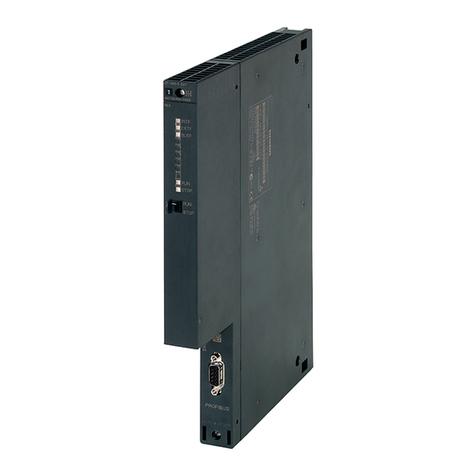
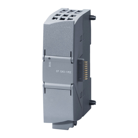
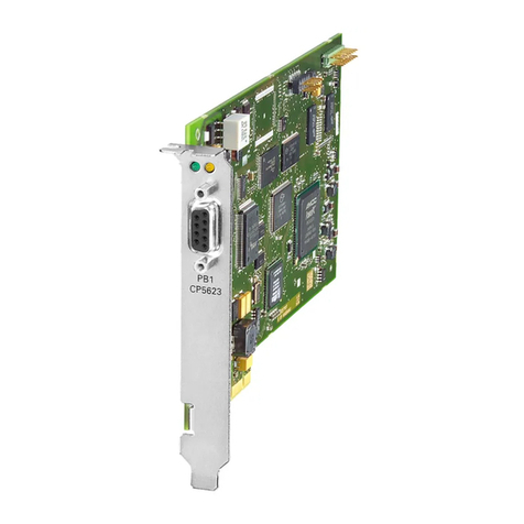
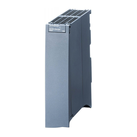
RF180C communication module
Operating Instructions, 12/2012, J31069-D0177-U001-A6-7618 3
Table of contents
1 Introduction................................................................................................................................................ 5
2 Description................................................................................................................................................. 7
3 Installation ............................................................................................................................................... 11
3.1 Mounting position, mounting dimensions.....................................................................................11
3.2 Mounting the I/O module..............................................................................................................12
3.3 Mounting the connection block ....................................................................................................13
3.4 Replacing labels...........................................................................................................................15
3.5 Disassembling the RF180C .........................................................................................................16
4 Connecting .............................................................................................................................................. 17
4.1 Wiring connection block M12, 7/8"...............................................................................................19
4.2 Wiring of the push-pull connection block .....................................................................................23
4.3 Loop-through connection of PROFINET IO and supply voltage..................................................26
4.4 Wiring an RF180C to a controller with RJ45 connector...............................................................28
4.5 Connecting the RF180C to functional ground (PE) .....................................................................28
5 Parameterization...................................................................................................................................... 31
5.1 PROFINET IO configuration ........................................................................................................31
5.2 Assigning device names to the I/O device...................................................................................32
5.3 Configuration parameters of the RF180C....................................................................................36
5.4 Input parameters for RF180C ......................................................................................................37
5.5 Command table of the RF180C ...................................................................................................40
6 Maintenance and service......................................................................................................................... 43
6.1 Replacing the RF180C communication module ..........................................................................43
6.2 Firmware update ..........................................................................................................................45
6.3 Reset to factory settings ..............................................................................................................48
7 Diagnostics.............................................................................................................................................. 49
7.1 Diagnosis using LEDs..................................................................................................................49
7.2 Parameterization of the diagnostics.............................................................................................51
7.3 Structure of the diagnostic data ...................................................................................................52
8 Technical data ......................................................................................................................................... 53
9 Dimension drawings ................................................................................................................................ 57
9.1 Dimension drawing for RF180C with fixing holes ........................................................................57
