Siemens HOTEL SOLUTION HTC3.1/A User manual
Other Siemens Control Unit manuals
Siemens
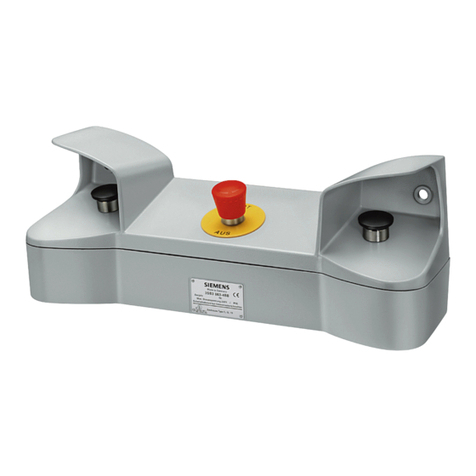
Siemens SIMOTION D410 User manual
Siemens
Siemens SIRIUS 3SB38 User manual
Siemens
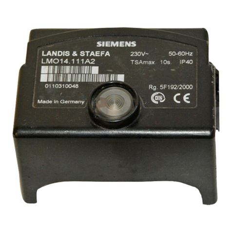
Siemens LMO14 Series User manual
Siemens
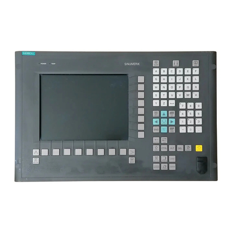
Siemens SINUMERIK 810D Quick start guide

Siemens
Siemens SINUMERIK 840D sl User manual
Siemens
Siemens SIPROTEC User manual
Siemens
Siemens 3RA2816-0EW20 User manual
Siemens
Siemens SINUMERIK 808D User manual
Siemens
Siemens K60R User manual
Siemens
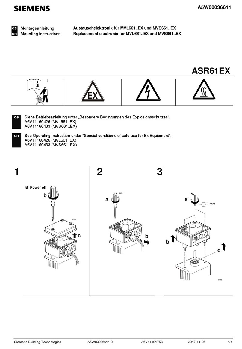
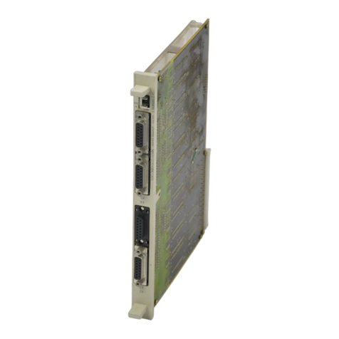
Siemens ASR61EX User manual
Siemens
Siemens WF 705 Operating and installation instructions
Siemens
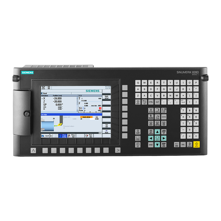
Siemens SINUMERIK 828D Turning Parts list manual
Siemens
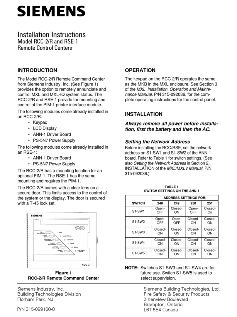
Siemens RCC-2/R User manual

Siemens
Siemens 7KM4211-1BA00-3AA0 User manual
Siemens
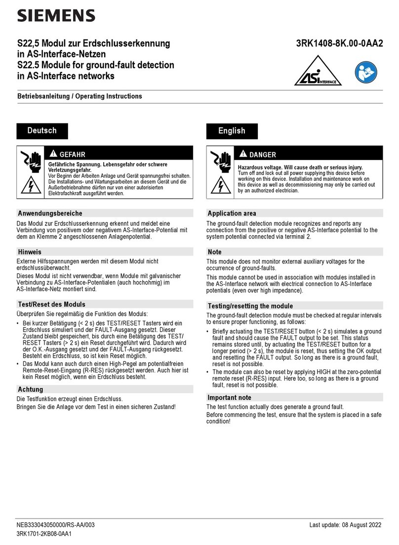
Siemens 3RK1408-8K.00-0AA2 User manual
Siemens
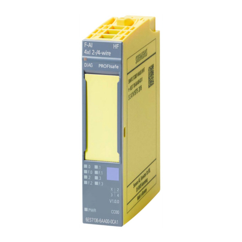
Siemens SIMATIC ET 200SP F-AI 4xI 0(4) 20mA 2-/4-wire HF... User manual
Siemens
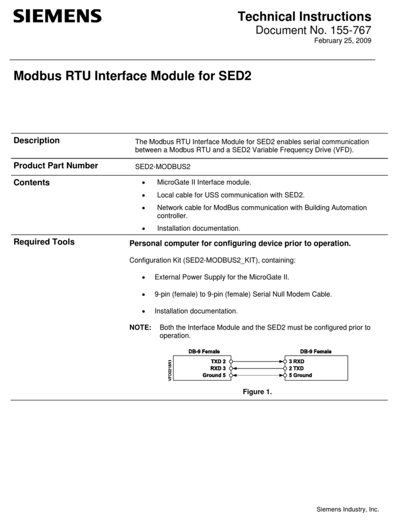
Siemens SED2-MODBUS2 Owner's manual
Siemens
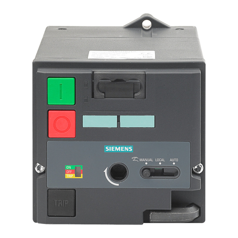
Siemens 3VL9800-3MJ00 User manual

Siemens
Siemens S7-1500 PROFIBUS User manual
Siemens
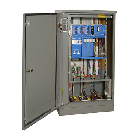
Siemens ST950 User manual
Popular Control Unit manuals by other brands

Festo
Festo Compact Performance CP-FB6-E Brief description

Elo TouchSystems
Elo TouchSystems DMS-SA19P-EXTME Quick installation guide

JS Automation
JS Automation MPC3034A user manual

JAUDT
JAUDT SW GII 6406 Series Translation of the original operating instructions

Spektrum
Spektrum Air Module System manual

BOC Edwards
BOC Edwards Q Series instruction manual

KHADAS
KHADAS BT Magic quick start

Etherma
Etherma eNEXHO-IL Assembly and operating instructions

PMFoundations
PMFoundations Attenuverter Assembly guide

GEA
GEA VARIVENT Operating instruction

Walther Systemtechnik
Walther Systemtechnik VMS-05 Assembly instructions

Altronix
Altronix LINQ8PD Installation and programming manual

