manuals.online logo
Brands
  1. Home
  2. •
  3. Brands
  4. •
  5. Siemens
  6. •
  7. Controllers
  8. •
  9. Siemens N526E02 User manual

Siemens N526E02 User manual

P.T.O.
instabus®
Technical Manual
Switch/Dimming Actuator
N526E02
5WG1 526–1EB02
June 2015 / Page 1
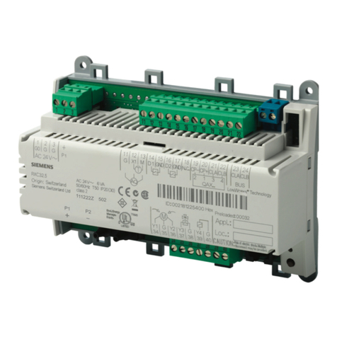
Product and Applications Description
The switching/dimming actuator N 526E02 is a N-
system DIN-rail mounted device for controlling up
to eight groups (channels) of fluorescent lamps via
the DC 1-10 V control terminal of dimmable elec-
tronic ballasts (e.g. ECG-Dynamic-type from Osram).
In addition there is per channel a switching contact
for direct switching on/off of the connected fluores-
cent lamps. This contact can be operated manually
via a slide switch which also indicates the actual
switching state of the channel (when switching
manually as well as when switching via the bus). A
channel is switched on when the slide is in the
lower position.
Different functions can be configured per channel
such as for switching on/off fluorescent lamps,
dimming up / down or setting a particular dimming
level.
With the ETS (Engineering Tool Software) the appli-
cation program is selected, its parameters and ad-
dresses are assigned appropriately and downloaded
into the switching/dimming actuator.
One channel of the N 526E02 switching/dimming
actuator can control several dimmable electronic
ballasts. Their number is limited by the switching
capacity and by the control power. If the on/off
function is not used via the switching contact of the
switching/dimming actuator, the number of control-
lable ECGs is only dependent on the load of the DC
1-10 V control voltage. This might allow to control a
larger number of ECGs (see Technical Specifications
below).
The power supply of the N 526E02 electronics is
provided via the bus (i.e. it requires no additional
power supply). When projecting an installation it
has to be considered that a N 526E02 represents a
double (and for short times even a triple) bus load
and takes up to 30 mA from the bus
.
Application Programs
The switching/dimming actuator N 526E02 works
only together with the application program 25 A8
Switch-/ Dimm Actuator 981301. This new applica-
tion program contains several modifications and
new functions (e.g. an integrated 8-bit scene con-
trol). The application program can be loaded from
ETS2 V1.3 onwards.
Technical Specifications
Power supply
·Bus voltage: DC 29V (Class 2) via the bus line
·Bus current:: Notice: the device represents at least a
double bus load and takes up to 30 mA from the bus.
Outputs
·8 outputs (latch relays, potential free contacts)
·rated voltage: AC 277 V, 50 ... 60 Hz
·rated current: 20 A, cos phi = 1
·switching current at AC 277 V: 0,1 ... 20 A, cos phi = 1
·DC switching current:
-DC 10 ... 30 V: max. 16 A, resistive load
- DC 230 V: max. 0,18 A, resistive load
·switching characteristic: to be set in parameter list (see
application program description)
Control voltage
·1 ... 10 V (provided by dimmable ballast)
·in case of bus voltage failure: 10 V
Control power
·dimmable electronic ballast: max 60 units
·signal amplifier: max 12 units
CAUTION
There is no protection of the control circuits against de-
struction by accidental connection to mains voltage!
Operating elements
·1 learning push button:
for toggling between normal mode/addressing mode
·8 slide switches for manual operation
(slide in upper position: relay contact open = OFF,
slide in lower position: relay contact closed = ON)
Display elements
·1 red LED:
for checking the bus voltage and for displaying normal
mode/addressing mode
·8 slide switches for displaying the switching position per
channel (see above)
Connections
·load and control circuit, physical:
insulation strip length 8 ... 9 mm
permissible conductor types/cross sections:
-0,5 ... 4 mm² single core
-0,5 ... 2,5 mm² flexible conductor
·load circuit, electrical:
-plain flexible conductor, min. 1 mm²:
current carrying capacity max. 6 A
-flexible conductor with terminal pin,
crimped on gas tight, min. 1,5 mm²:
current carrying capacity max. 10 A
-all other conductors, min. 1,5 mm²:
current carrying capacity max. 16 A
CAUTION
When looping through the L-conductor (connection blocks 1
and 2, 4 and 5, 7 and 8, 10 and 11, 13 and 14, 16 and 17,
19 and 20, 22 and 23), take care that the maximum connec-
tion current of 20 A (as governed by the maximum permissi-
ble printed conductor load) is not exceeded!
·Bus line:
-pressure contacts on data-rail
-screwless bus connection block,
Ø 0,6 ... 0,8 mm single core,
insulation strip length 5 mm
Physical specifications
·polymer casing
·N-system DIN-rail mounted device,
width: 8 MU (1 MU = 18 mm)
·weight: approx. 470 g (29oz)
·installation: rapid mounting on DIN rail complying with
EN 60715-TH35-7,5
Electromagnetic compatibility
complies with Part 15 of the FCC rules pursuant to the limits
for a Class A digital device
Environmental specifications
• ambient temperature operating: - 5 ... + 45° C (23...113°F)
• maximum ambient temperature range: - 25 ... + 70° C
(-13...158°F)
• relative humidity (non-condensing): 5 % to 93 %
Listings and Certifications
UL listed (E464611)
UL 916, Open Energy Management Equipment
CSA certified
CE marked
In accordance with the EMC guideline (residential and func-
tional buildings) and the low voltage guideline.
KNX / EIB certified
Markings
KNX, EIB, CE, UL
USA
A5E01695896A - DS04
instabus®
Technical Manual
Switch/Dimming Actuator
N526E02
5WG1 526-1EB02
June 2015 / Page 2
B1
C2
C3
B2
C1
D1.1
D1
( 9,5mm)
E1.1
E1.2
E1
3/ 8“
Location and Function of the Display
and Control Elements
0
A4 A3 A2 A1
A5
A6
A1 LED for indicating normal operating mode (LED off)
and addressing mode (LED on); upon receiving the
physical address the device automatically returns to
normal operating mode
A2 Learning button for switching between normal oper-
ating mode and addressing mode
A3 bus connection block, screw-less
A4 screw terminals for connecting the control circuits
A5 Slide switches for manual operation and for displaying
the switching position per channel.
Slide in upper position: relay contact open (OFF)
Slide in lower position: relay contact closed (ON)
A6 mains connection blocks (screw terminals) for
connecting load circuits
Important note:
Manual operation is for emergency operation only and not af-
fecting the application program. No telegram is sent on the
bus, and the new switching status is unknown to the soft-
ware.
At bus voltage failure / recovery a previously manually oper-
ated relay will also be set automatically to the configured po-
sition.
Installation Instructions
The device may be used for permanent interior installations
in dry locations within distribution boards or small casings
with DIN rail EN 60715-TH35-7,5.
This equipment is intended for field installation within the
enclosure of another product.
Typical circuit
N
PE
L
+
-
26
3
+
-
N
PE
L
+
-
26
+
-
N
PE
L
+
-
26
+
-
Switching/Dimming
Actuator N 526E
N
PE
L
Load circuit
mains voltage
L1 PE N
ECG Dynamic
+
-
26
25
fluorescent lamp
+
-
Channel A
buscouplingunit
Control
DC0...10V
Supply
mainsvoltage
Switching
mainsvoltage
Dimming
DC0...10V
instabus
EIB
2
1
L
L
Mounting
General description
The N-system DIN-rail device can be installed in the
instabus EIB lighting control panel, surface or flush mounted,
or to any DIN rail in distribution boards, surface or flush
mounted,complying with EN 60715-TH35-7,5 that has a da-
ta rail installed.
The connection to the bus line is established by clicking the
device onto the DIN-rail (with a data rail installed). Take care
that the type plates of all devices on a DIN-rail can be read in
the same direction, guaranteeing the devices are polarised
correctly.
Mounting the Power Supply unit N 125 to a DIN-rail
• Slide the DIN-rail device (B1) onto the DIN-rail (B2) and
• swivel back the DIN-rail device until the slide clicks into
place audibly.
Dismounting DIN-rail devices
• Remove all connected wires,
• press down the slide (C3) with a screw-driver and
• swivel the DIN-rail device (C1) from the DIN-rail (C2).
Connection to the bus without data rail
If the connection is established via bus connection block
(data rail not installed) the data rail connection system has to
be covered with the enclosed insulation hood after removing
the guiding hood e.g. with a screw driver to guarantee a suf-
ficient insulation from the DIN rail.
Removing the guiding top
-The guiding top (D3) surrounds the contact system (D2)
on the back side of the device (D1).
-Insert the screw driver between the DIN-rail device (D1)
and the guiding hood (D3) and remove the guiding hood.
Inserting the insulation top
-Put the insulation top (D4) onto the contact system and
click it into place by a slight pressure.
Wiring
Connecting mains
• Mains is connected via screwless plug-in terminals (D1).
• Remove approx. 3/8" (9,5mm) of insulation from the wire
(D1.1) and plug it into the terminal (D1).
Disconnect mains
• Press the terminal lock (E1.2) with a screw-driver and
• remove the wire (E1.1) from the terminal (E1).
E1
E2
5 mm
E1
E2
Slipping on of the safety extra low voltage block
-slip the connection block onto the guide slot and
-press the connection block down to the stop
Connecting the safety extra low voltage block
-The connection block (E1) can be used with single core
conductors Ø 0,6 ... 0,8 mm.
-Remove approx. 5 mm of insulation from the conductor
(E2) and plug it into the connection block (E1) (red = +,
black = -).
Disconnecting the safety extra low voltage block
-Unplug the connection block (E1) and remove the bus ca-
ble conductor (E2) while simultaneously wiggling it.
D3 D1 D2 D2 D4 D1
WARNING
WARNING
Hazardous voltage. Can cause death, or serious injury or property damage.
Disconnect and lock off power before installing or working on the device.
Risk of Electric Shock – More than one disconnect switch may be required to de-
energize the equipment before servicing.
The device must not be opened.
A faulty device should be returned to the local Siemens sales office or distributor.
The device must be mounted and commissioned by a factory trained person.
The prevailing safety rules must be observed!
Mount in dry locations only!

This manual suits for next models

1

Other Siemens Controllers manuals

Siemens ECOFAST 3RK1303 S AA Series User manual

Siemens

Siemens ECOFAST 3RK1303 S AA Series User manual

Siemens SIMATIC TI555 User guide

Siemens

Siemens SIMATIC TI555 User guide

Siemens SINAMICS S120 Quick start guide

Siemens

Siemens SINAMICS S120 Quick start guide

Siemens GNA 1E Series User manual

Siemens

Siemens GNA 1E Series User manual

Siemens Synco 700 User manual

Siemens

Siemens Synco 700 User manual

Siemens SSA911.01TH User manual

Siemens

Siemens SSA911.01TH User manual

Siemens RWD45U User manual

Siemens

Siemens RWD45U User manual

Siemens SIMATIC S7-1200 User manual

Siemens

Siemens SIMATIC S7-1200 User manual

Siemens Simatic S7 Series User manual

Siemens

Siemens Simatic S7 Series User manual

Siemens GGA 1E Series User manual

Siemens

Siemens GGA 1E Series User manual

Siemens SINUMERIK 840D sl User manual

Siemens

Siemens SINUMERIK 840D sl User manual

Siemens SKP Series Owner's manual

Siemens

Siemens SKP Series Owner's manual

Siemens SSE161.05U User manual

Siemens

Siemens SSE161.05U User manual

Siemens PXC Series User manual

Siemens

Siemens PXC Series User manual

Siemens SIDS-T40026-00-4AUS User manual

Siemens

Siemens SIDS-T40026-00-4AUS User manual

Siemens Powermite 599 Series Owner's manual

Siemens

Siemens Powermite 599 Series Owner's manual

Siemens Simatic S7-300 User manual

Siemens

Siemens Simatic S7-300 User manual

Siemens SIMATIC S5-115U User manual

Siemens

Siemens SIMATIC S5-115U User manual

Siemens SIRIUS 3RW3003 User manual

Siemens

Siemens SIRIUS 3RW3003 User manual

Siemens REV13 series User manual

Siemens

Siemens REV13 series User manual

Siemens GXD 31.1 Series User manual

Siemens

Siemens GXD 31.1 Series User manual

Siemens SIRIUS 3RA1.5 User manual

Siemens

Siemens SIRIUS 3RA1.5 User manual

Siemens SINAMICS S120 User manual

Siemens

Siemens SINAMICS S120 User manual

Siemens SITRANS I100 7NG4124-0AA00 User manual

Siemens

Siemens SITRANS I100 7NG4124-0AA00 User manual

Popular Controllers manuals by other brands

MicroPROGEL TC543 operating instructions

MicroPROGEL

MicroPROGEL TC543 operating instructions

Honeywell H46C installation instructions

Honeywell

Honeywell H46C installation instructions

Biegler autopress e Instructions for use

Biegler

Biegler autopress e Instructions for use

AirCom RH300 operating manual

AirCom

AirCom RH300 operating manual

Zennio DIMinBOX 2CH ZDI-DB2C quick start guide

Zennio

Zennio DIMinBOX 2CH ZDI-DB2C quick start guide

Mitsubishi AJ65BT-64RD3 user manual

Mitsubishi

Mitsubishi AJ65BT-64RD3 user manual

Danfoss VLTAutomationDrive FC 360 quick guide

Danfoss

Danfoss VLTAutomationDrive FC 360 quick guide

Elk Products ELK-130 manual

Elk Products

Elk Products ELK-130 manual

Auber Instruments EZboil DSPR310D instruction manual

Auber Instruments

Auber Instruments EZboil DSPR310D instruction manual

Okolab H301-EC-LG-BL user manual

Okolab

Okolab H301-EC-LG-BL user manual

Knoll MR200 Installation and operating instructions

Knoll

Knoll MR200 Installation and operating instructions

PI E-651.1S operating manual

PI

PI E-651.1S operating manual

Nexus Audio C-4.4 installation instructions

Nexus Audio

Nexus Audio C-4.4 installation instructions

Omron R88A-MCW151 Series datasheet

Omron

Omron R88A-MCW151 Series datasheet

Pasco Scientific SF-9216 instruction manual

Pasco Scientific

Pasco Scientific SF-9216 instruction manual

ADVATEK LIGHTING PixLite T8-S Mk3 quick start guide

ADVATEK LIGHTING

ADVATEK LIGHTING PixLite T8-S Mk3 quick start guide

Fri-Jado 9128135 Technical manual

Fri-Jado

Fri-Jado 9128135 Technical manual

Timotion MA1_AC user manual

Timotion

Timotion MA1_AC user manual

manuals.online logo
manuals.online logoBrands
  • About & Mission
  • Contact us
  • Privacy Policy
  • Terms and Conditions

Copyright 2025 Manuals.Online. All Rights Reserved.