manuals.online logo
Brands
  1. Home
  2. •
  3. Brands
  4. •
  5. Siemens
  6. •
  7. Industrial Electrical
  8. •
  9. Siemens 5WG1 120-1AB02 Service manual

Siemens 5WG1 120-1AB02 Service manual

Other Siemens Industrial Electrical manuals

Siemens Modbus Driver User manual

Siemens

Siemens Modbus Driver User manual

Siemens SIRIUS 3RV19 Series User manual

Siemens

Siemens SIRIUS 3RV19 Series User manual

Siemens 3WN1 User manual

Siemens

Siemens 3WN1 User manual

Siemens SMP16-SFT251 Parts list manual

Siemens

Siemens SMP16-SFT251 Parts list manual

Siemens SIRIUS 3ZX1012-0RT02-1AA1 User manual

Siemens

Siemens SIRIUS 3ZX1012-0RT02-1AA1 User manual

Siemens SIMATIC NET RUGGEDCOM RX1536 Technical Document

Siemens

Siemens SIMATIC NET RUGGEDCOM RX1536 Technical Document

Siemens SIPLUS HCS4 00 Series Quick guide

Siemens

Siemens SIPLUS HCS4 00 Series Quick guide

Siemens SIVACON 8PS User manual

Siemens

Siemens SIVACON 8PS User manual

Siemens 3VA9078-0VM10 User manual

Siemens

Siemens 3VA9078-0VM10 User manual

Siemens SINAMICS G130 User manual

Siemens

Siemens SINAMICS G130 User manual

Siemens SIMATIC RTLS User manual

Siemens

Siemens SIMATIC RTLS User manual

Siemens SIMATIC ET 200SP User manual

Siemens

Siemens SIMATIC ET 200SP User manual

Siemens SITRANS LVS100 User manual

Siemens

Siemens SITRANS LVS100 User manual

Siemens SIRIUS 3RH14 1 Series User manual

Siemens

Siemens SIRIUS 3RH14 1 Series User manual

Siemens BD01-GK User manual

Siemens

Siemens BD01-GK User manual

Siemens 3NJ4910-1AA00 User manual

Siemens

Siemens 3NJ4910-1AA00 User manual

Siemens SIRIUS 8WD44 User manual

Siemens

Siemens SIRIUS 8WD44 User manual

Siemens SIRIUS 3RA232 8 Series User manual

Siemens

Siemens SIRIUS 3RA232 8 Series User manual

Siemens STF 3VA9988-0BA Series User manual

Siemens

Siemens STF 3VA9988-0BA Series User manual

Siemens SINAMICS G120 Administrator guide

Siemens

Siemens SINAMICS G120 Administrator guide

Siemens 3VM1 Series User manual

Siemens

Siemens 3VM1 Series User manual

Siemens SIMATIC ET 200SP User manual

Siemens

Siemens SIMATIC ET 200SP User manual

Siemens 3VA9603-0QE00 User manual

Siemens

Siemens 3VA9603-0QE00 User manual

Siemens 3VA1 Series User manual

Siemens

Siemens 3VA1 Series User manual

Popular Industrial Electrical manuals by other brands

Murata GRM0335C1E3R9BA01 Series Reference sheet

Murata

Murata GRM0335C1E3R9BA01 Series Reference sheet

ARCAIR N6000 Automatic System Safety and operating instructions

ARCAIR

ARCAIR N6000 Automatic System Safety and operating instructions

Murata GRM31CR61E106MA12 Series Reference sheet

Murata

Murata GRM31CR61E106MA12 Series Reference sheet

Murata GQM2195C2A9R1CB01 Series Reference sheet

Murata

Murata GQM2195C2A9R1CB01 Series Reference sheet

MFJ MFJ-918 quick start guide

MFJ

MFJ MFJ-918 quick start guide

Abtech HVJB Series Installation, operation & maintenance instructions

Abtech

Abtech HVJB Series Installation, operation & maintenance instructions

Murata GRM0335C1H8R1DA01 Series Reference sheet

Murata

Murata GRM0335C1H8R1DA01 Series Reference sheet

SAF-HOLLAND CBX 5415.5 Installation and operation manual

SAF-HOLLAND

SAF-HOLLAND CBX 5415.5 Installation and operation manual

Eaton Ulusoy HMH24-04 user manual

Eaton

Eaton Ulusoy HMH24-04 user manual

Murata GJM0335C1E4R4BB01 Series Reference sheet

Murata

Murata GJM0335C1E4R4BB01 Series Reference sheet

Newlong NP-7H NSTRUCTION MANUAL/PARTS LIST

Newlong

Newlong NP-7H NSTRUCTION MANUAL/PARTS LIST

Stahl 8575/12 operating instructions

Stahl

Stahl 8575/12 operating instructions

SI Pegasus installation instructions

SI

SI Pegasus installation instructions

Murata GRM1555C1H2R7CA01 Seies Reference sheet

Murata

Murata GRM1555C1H2R7CA01 Seies Reference sheet

Murata GRM0225C1E6R4BA03 Series Reference sheet

Murata

Murata GRM0225C1E6R4BA03 Series Reference sheet

Cooper Power Systems VXE15 Installation and operation instructions

Cooper Power Systems

Cooper Power Systems VXE15 Installation and operation instructions

S&C Vista SD manual

S&C

S&C Vista SD manual

Murata GRM0335C2A7R3CA01 Series Reference sheet

Murata

Murata GRM0335C2A7R3CA01 Series Reference sheet

manuals.online logo
manuals.online logoBrands
  • About & Mission
  • Contact us
  • Privacy Policy
  • Terms and Conditions

Copyright 2025 Manuals.Online. All Rights Reserved.

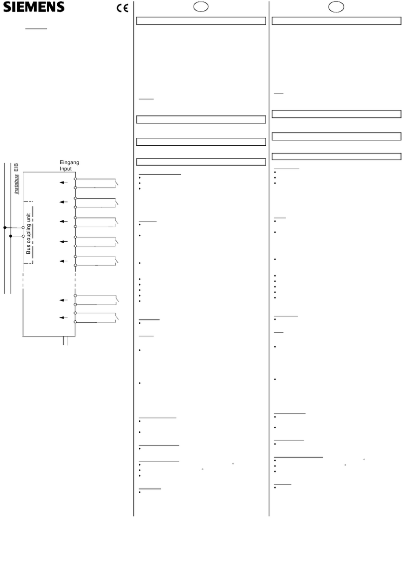
GAMMA instabus
Drossel N120/02 5WG1 120-1AB02
Choke N120/02
Bedien- und Montageanleitung
Operating and Mounting Instructions
Stand: April 2005
Issued: April 2005
Spannungs-
versorgung N 125/01
Datenschiene:
äußere Leiterbahnen:
frei
innere Leiterbahnen:
Buslinie
Verbinder
N 191
Linie 0
(Hauptlinie)
instabus EIB
Datenschiene:
äußere Leiterbahnen:
frei
innere Leiterbahnen:
Buslinie
Spannungs-
versorgung
N 125/21
Linien-/ Bereichs-
koppler N 140/3
Verbinder
REG 191/01
Linie 1
Linie 1
Datenschiene:
äußere Leiterbahnen:
DC 24V
innere Leiterbahnen:
Buslinie
Linien-/ Bereichs-
koppler N 140/3
Linie 2
Drossel
N 120/02
L1 N Erde
AC 120...230 V
Bus
Bus
L1 N Erde
AC 120...230 V
DC 24 V
N 125/11
DC 24 V
(Verbindung zu
DC 24V von N 125/21)
Bild / Figure 1
D
Produkt- und Funktionsbeschreibung
Zur Versorgung der Busteilnehmer wird die notwendige Versor-
gungsspannung zusammen mit den Datentelegrammen auf ei-
ner gemeinsamen Leitung übertragen.
Die Drossel N 120/02 verhindert den Kurzschluß der Datentele-
gramme auf der Buslinie durch die Versorgungsspannung. Sie
erhält die DC 29V Versorgungsspannung über die Kleinspan-
nungsklemme (weiß-gelbe Klemme). Die Versorgungsspannung
wird auch an die beiden äußeren Leiterbahnen der Datenschie-
ne weiterleitet und wird über Induktivitäten auf die beiden in-
neren Leiterbahnen und die Busklemme (schwarz-rote Klemme)
gespeist.
Die Versorgungsspannung kann über die Kleinspannungsklem-
me (weiß-gelbe Klemme) von der Spannungsversorgung
N 125/21 auf die beiden äußeren Leiterbahnen der Datenschie-
ne eingespeist werden.
Durch den eingebauten Resetschalter (Betätigung >10s) wer-
den die Busteilnehmer in den Grundzustand gesetzt, d.h. nach
dem Wiedereinschalten nehmen die Busteilnehmer ihren vor-
gegebenen Grundzustand ein. Dabei wird die Buslinie kurzge-
schlossen und die Versorgungsspannung abgeschaltet.
Für die Gleichspannung der Versorgungsspannung ist der Dros-
selwiderstand niederohmig. Da die Informationen über den
instabus EIB in Form einer Wechselspannung übertragen wer-
den, ist die Drossel N 120/02 für sie hochohmig. Dadurch stellt
die Versorgungsspannung nur eine geringe Belastung für das
Informationssignal dar.
Weitere Informationen
http://www.siemens.de/gamma
Anschlussbeispiel
siehe Bild 1
Technische Daten
Eingangsspannung
•Bemessungsspannung: DC 29 V (DC 28...30V)
•Bemessungsstrom: 640 mA
Anschlüsse
•Spannungsversorgung:
- Druckkontakte auf Datenschiene (äußere Leiterbahnen)
- Kleinspannungsklemme (gelb-weiss), schraubenlos
0,6...0,8mm Ø eindrähtig
•Buslinie:
- Druckkontakte auf Datenschiene (innere Leiterbahnen)
- Busklemme (schwarz-rot), schraubenlos
0,6...0,8mm Ø eindrähtig
Mechanische Daten
•Abmessungen: Reiheneinbaugerät im N-Maß,
Breite 2 TE (1 TE = 18 mm)
•Gewicht: ca. 100 g
Elektrische Sicherheit
•Schutzart (nach EN 60529): IP 20
Umweltbedingungen
•Klimabeständigkeit: EN 50090-2-2
•Umgebungstemperatur im Betrieb: - 5 ... + 45 °C
•Lagertemperatur: - 25 ... + 70 °C
•rel. Feuchte (nicht kondensierend): 5 % bis 93 %
Seite 1 von 2
GB
Product and Applications Description
The operating voltage for the bus devices supplied through the
bus is transmitted via the same twisted pair cable as the data
telegrams.
The choke N 120/02 prevents the DC 29V power-supply from
short-circuiting the data telegram on the bus line. The choke re-
ceives the power via the low-voltage connector (yellow-white)
on the front side. This power is directly connected to the two
outer printed conductors of the data rail. It is fed via inductors
to the two inner printed conductors of the data rail and to the
bus connector terminal (black-red) on the front side of the de-
vice.
The DC 29V supply voltage fed to the low-voltage connector
(yellow-white) may be sourced from a power supply unit
N 125/21. It may also be sourced from a power supply N123 via
the data rail.
Via the built-in reset-switch (operation > 10 s) the bus devices
are set to their default setting, i.e. the bus devices return to
their default setting with the recurring supply voltage. This is
done by short-circuiting the bus line and switching off the sup-
ply voltage.
To the DC 29V supply voltage the choke resistance is
low. To the data signal transmitted on instabus EIB, which is an
alternating current, the resistance of the choke N 120/02 is high
and therefore the operating voltage supply does not signifi-
cantly affect the information signal.
Additional Information
http://www.siemens.com/gamma
Example of Operation
see figure 1
Technical Specifications
Input voltage
•rated voltage: DC 29 V (DC 28...30V)
•rated current: 640 mA
Connections
•power supply:
- pressure contacts on data rail (outer printed conductors)
- screwless extra low voltage terminal (yellow-white)
∅0,6 ... 0,8 mm, solid single-core copper wire
•bus line:
- pressure contacts on data rail (inner printed conductors),
- screwless extra low voltage terminal (red–black)
∅0,6 ... 0,8 mm, solid single-core copper wire
Physical specifications
•N-system DIN-rail mounted device,
width: 2 SUs (1 SU = 18 mm)
•weight: approx. 100 g
Electrical safety
•protection (according to EN 60529): IP 20
Environmental specifications
•climatic conditions: EN 50090-2-2
•ambient temperature operating: - 5 ... + 45 °C
•ambient temperature non-op.: - 25 ... + 70 °C
•relative humidity (non-condensing): 5 % to 93 %
page 1 of 2 2515044115
DS 01
A1
A5
A7
A6
A4
Reset
A2 A3
Bild / Figure 2
B1 C1
C2
C3
B2
Bild / Figure 3
D1
D2
D2
D2.4
D2 D2.4
5 mm
D2.1 D2.2
2
D2.3
D
Bild / Figure 4
Bild / Figure 5
D
Lage- und Funktion der Anzeige- und Bedienelemente
A1 Reset-Schalter
Schiebeschalter zum Rücksetzen der an der Linie ange-
schlossenen Busteilnehmer (Betätigung > 10s)
A2 Reset-Stellung
A3 Betriebsstellung
A4 Typenschild
A5 LED zur Anzeige der Resetstellung (LED ein)
A6 Busklemme (schwarz-rot) für Buslinie
A7 Kleinspannungsklemme (gelb-weiß) für DC 24V Span-
nungsversorgung
Montage und Verdrahtung
Das Gerät kann für feste Installation in trockenen Innenräumen,
zum Einbau in Starkstromverteiler oder Kleingehäuse auf Hut-
schienen EN 60715-TH35-7,5 verwendet werden.
Montage und Demontage des Gerätes: siehe Bild 3
Busleitung anschließen und abklemmen: siehe Bild 4
Spannungsversorgung anschließen und abklemmen: siehe Bild
4
Montieren der Isolierkappe
Soll das Gerät auf einer Hutschiene ohne eingeklebte Daten-
schiene montiert werden, so ist das Kontaktsystem mit der mit-
gelieferten Isolierkappe abzudecken.
Abnehmen der Fixierung: siehe Bild 5
-Die Fixierung (E3) umschließt das Kontaktsystem (E2) auf der
Rückseite des Gerätes (E1).
-Den Schraubendreher zwischen dem Reiheneinbaugerät (E1)
und der Fixierung (E3) einführen und die Fixierung heraus-
ziehen.
Aufschnappen der Isolierkappe: siehe Bild 5
-Die Isolierkappe (E4) auf das Kontaktsystem stecken und
durch Drücken aufschnappen.
VWARNUNG
•Das Gerät darf nur von einer zugelassenen Elektrofachkraft
installiert und in Betrieb genommen werden.
•Freie Hutschienenbereiche mit eingelegter Datenschiene
sind mit Abdeckung 5WG1 192-8AA01
abzudecken.
•Die geltenden Sicherheits- und Unfallverhütungsvorschriften
sind zu beachten.
•Das Gerät darf nicht geöffnet werden.
•Bei der Planung und Errichtung von elektrischen Anlagen
sind die einschlägigen Richtlinien, Vorschriften und Bestim-
mungen des jeweiligen Landes zu beachten.
Allgemeine Hinweise
•Die Bedienungsanleitung ist dem Kunden auszuhändigen.
•Ein defektes Gerät ist an die zuständige Geschäftsstelle der
Siemens AG zu senden.
•Bei zusätzlichen Fragen zum Produkt wenden Sie sich bitte
an unseren Technical Support:
!+49 (180) 5050-222
!+49 (180) 5050-223
"www.siemens.de/automation/support-request
Seite 2 von 2
GB
Location and Function of the Display and Operating Elements
A1 Reset switch
slide switch for re-setting the bus devices connected to the
line (operation > 10 s)
A2 Reset position
A3 Operating position
A4 Type label
A5 LED indicating reset position (LED on)
A6 Bus connector (black-red) for bus line
A7 Low-voltage connector (yellow-white) for DC 24V power
supply
Mounting and wiring
The device may be used for permanent interior installations in
dry locations within distribution boards or small casings with
DIN rail EN 60715-TH35-7,5.
Mounting / dismounting the device: see figure 3
Connecting / disconnecting the bus cable: see figure 4
Connecting / disconnecting the power supply: see figure 4
Mounting the insulating cap
If the device should be mounted on a DIN rail without a data
rail, the contact system must be covered with the supplied insu-
lating cap.
Removing the locating clamp: see figure 5
-The locating clamp (E3) encloses the contact system (E2) on
the rear of the device (E1).
-Insert the screwdriver between the DIN rail mounted device
(E1) and the locating clamp (E3) and remove the clamp.
Clipping on the insulation cap: see figure 5
-Place the insulating cap (E4) on the contact system and press
so that it snaps in place.
VWARNING
•The device must be mounted and commissioned by an
authorised electrician.
•Unassigned sections of DIN rail with inserted data rail must
be covered using 5WG1 192-8AA01.
•The prevailing safety rules must be heeded.
•The device must not be opened.
•For planning and construction of electric installations, the
relevant guidelines, regulations and standards of the respec-
tive country are to be considered.
General Notes
•The operating instructions must be handed over to the client.
•Any faulty device should be returned to the local Siemens of-
fice.
•If you have further questions concerning the product please
contact our technical support.
!+49 (180) 5050-222
!+49 (180) 5050-223
"www.siemens.de/automation/support-request
page 2 of 2
2515044115
DS 01
E3 E1 E2 E2 E4 E1