manuals.online logo
Brands
  1. Home
  2. •
  3. Brands
  4. •
  5. Siemens
  6. •
  7. Industrial Electrical
  8. •
  9. Siemens HM656A User manual

Siemens HM656A User manual

Other Siemens Industrial Electrical manuals

Siemens SIMOVERT MASTERDRIVE SLE User manual

Siemens

Siemens SIMOVERT MASTERDRIVE SLE User manual

Siemens SIRIUS 3ZX1012-0RT02-1AA1 User manual

Siemens

Siemens SIRIUS 3ZX1012-0RT02-1AA1 User manual

Siemens 3NC2391-0MK User manual

Siemens

Siemens 3NC2391-0MK User manual

Siemens MICROMASTER 440 Operating and maintenance instructions

Siemens

Siemens MICROMASTER 440 Operating and maintenance instructions

Siemens 3VA9603-0QE00 User manual

Siemens

Siemens 3VA9603-0QE00 User manual

Siemens SIMATIC ET 200pro FC-2 User manual

Siemens

Siemens SIMATIC ET 200pro FC-2 User manual

Siemens 3VA9.70-0WC00 User manual

Siemens

Siemens 3VA9.70-0WC00 User manual

Siemens SENTRON SUPERSWITCH 3KL82 Series User manual

Siemens

Siemens SENTRON SUPERSWITCH 3KL82 Series User manual

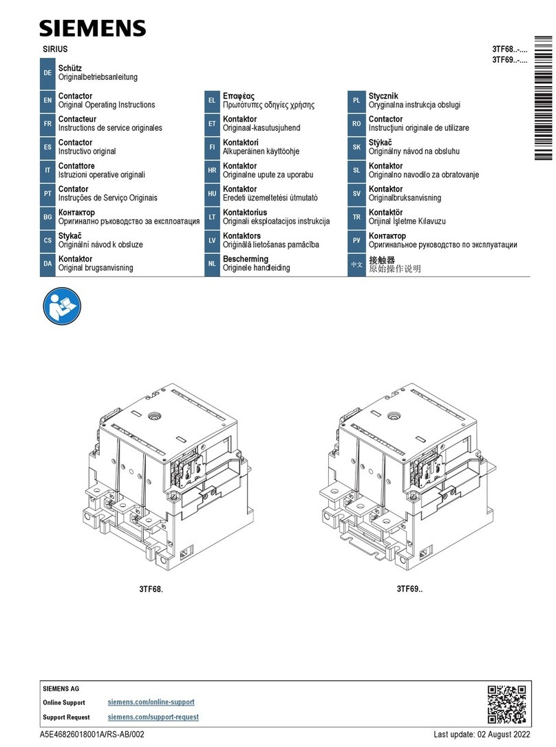
Siemens SIRIUS 3TF68 Series User manual

Siemens

Siemens SIRIUS 3TF68 Series User manual

Siemens Milltronics MILLFLO User manual

Siemens

Siemens Milltronics MILLFLO User manual

Siemens 3TS33 User manual

Siemens

Siemens 3TS33 User manual

Siemens 3VA9988-0BM10 User manual

Siemens

Siemens 3VA9988-0BM10 User manual

Siemens 5WG1 120-1AB02 Service manual

Siemens

Siemens 5WG1 120-1AB02 Service manual

Siemens VT250 User manual

Siemens

Siemens VT250 User manual

Siemens SENTRON 3KF SITOR User manual

Siemens

Siemens SENTRON 3KF SITOR User manual

Siemens SIVACON 8PS BD2 Series User manual

Siemens

Siemens SIVACON 8PS BD2 Series User manual

Siemens SIMATIC ET 200SP User manual

Siemens

Siemens SIMATIC ET 200SP User manual

Siemens 3VA94-0KP00 Series User manual

Siemens

Siemens 3VA94-0KP00 Series User manual

Siemens 3VA9117-0HB 0 Series User manual

Siemens

Siemens 3VA9117-0HB 0 Series User manual

Siemens SINAMICS G120P User manual

Siemens

Siemens SINAMICS G120P User manual

Siemens SINAMICS G130 User manual

Siemens

Siemens SINAMICS G130 User manual
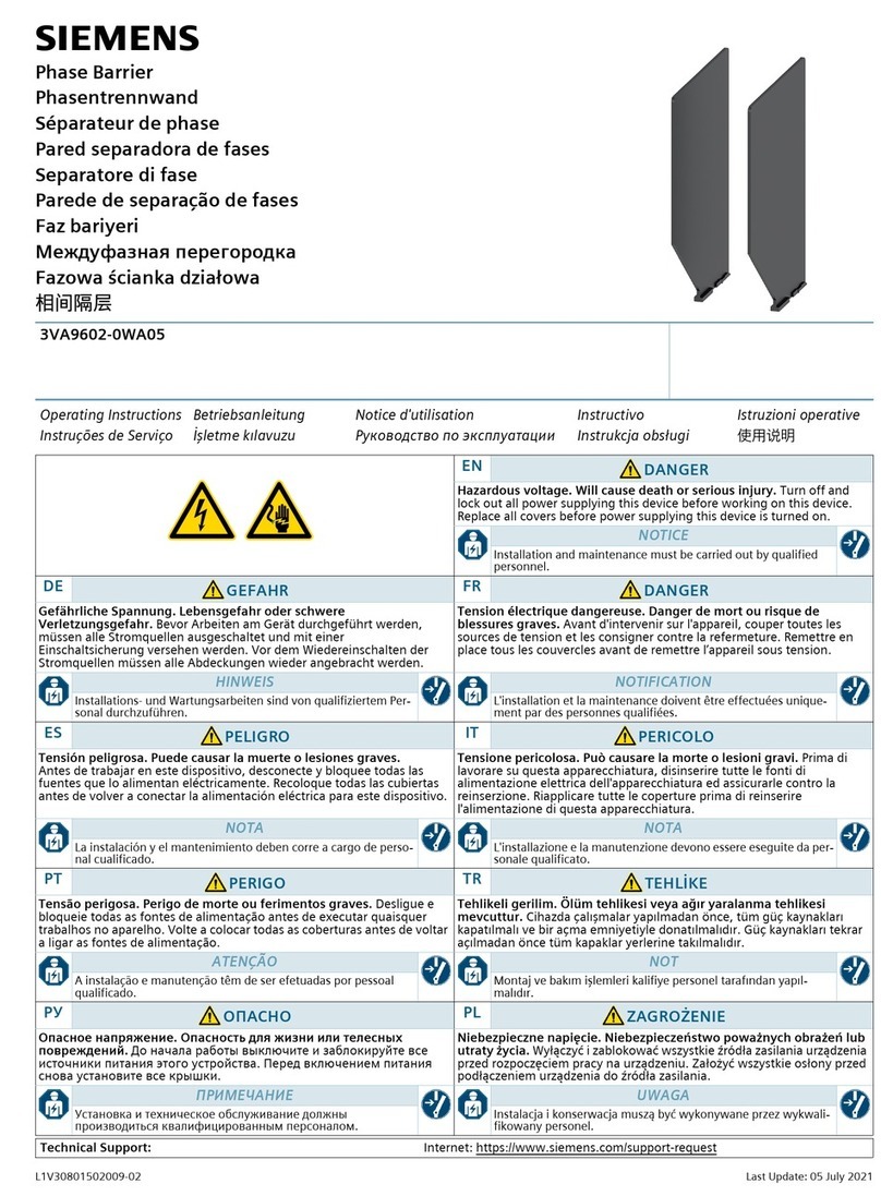
Siemens SINAMICS Instruction sheet

Siemens

Siemens SINAMICS Instruction sheet

Siemens SIPLUS HCS4 00 Series Quick guide

Siemens

Siemens SIPLUS HCS4 00 Series Quick guide

Siemens 6300A User manual

Siemens

Siemens 6300A User manual

Popular Industrial Electrical manuals by other brands

Murata GRM0335C1E3R9BA01 Series Reference sheet

Murata

Murata GRM0335C1E3R9BA01 Series Reference sheet

ARCAIR N6000 Automatic System Safety and operating instructions

ARCAIR

ARCAIR N6000 Automatic System Safety and operating instructions

Murata GRM31CR61E106MA12 Series Reference sheet

Murata

Murata GRM31CR61E106MA12 Series Reference sheet

Murata GQM2195C2A9R1CB01 Series Reference sheet

Murata

Murata GQM2195C2A9R1CB01 Series Reference sheet

MFJ MFJ-918 quick start guide

MFJ

MFJ MFJ-918 quick start guide

Abtech HVJB Series Installation, operation & maintenance instructions

Abtech

Abtech HVJB Series Installation, operation & maintenance instructions

Murata GRM0335C1H8R1DA01 Series Reference sheet

Murata

Murata GRM0335C1H8R1DA01 Series Reference sheet

SAF-HOLLAND CBX 5415.5 Installation and operation manual

SAF-HOLLAND

SAF-HOLLAND CBX 5415.5 Installation and operation manual

Eaton Ulusoy HMH24-04 user manual

Eaton

Eaton Ulusoy HMH24-04 user manual

Murata GJM0335C1E4R4BB01 Series Reference sheet

Murata

Murata GJM0335C1E4R4BB01 Series Reference sheet

Newlong NP-7H NSTRUCTION MANUAL/PARTS LIST

Newlong

Newlong NP-7H NSTRUCTION MANUAL/PARTS LIST

Stahl 8575/12 operating instructions

Stahl

Stahl 8575/12 operating instructions

SI Pegasus installation instructions

SI

SI Pegasus installation instructions

Murata GRM1555C1H2R7CA01 Seies Reference sheet

Murata

Murata GRM1555C1H2R7CA01 Seies Reference sheet

Murata GRM0225C1E6R4BA03 Series Reference sheet

Murata

Murata GRM0225C1E6R4BA03 Series Reference sheet

Cooper Power Systems VXE15 Installation and operation instructions

Cooper Power Systems

Cooper Power Systems VXE15 Installation and operation instructions

S&C Vista SD manual

S&C

S&C Vista SD manual

Murata GRM0335C2A7R3CA01 Series Reference sheet

Murata

Murata GRM0335C2A7R3CA01 Series Reference sheet

manuals.online logo
manuals.online logoBrands
  • About & Mission
  • Contact us
  • Privacy Policy
  • Terms and Conditions

Copyright 2025 Manuals.Online. All Rights Reserved.

Recommended tools:
5/16” socket,
Extension bar,
Torque wrench
1 / 10 (English)
400A & 600A
Mechanism Replacement Kit
Installation Instructions
Turn off and lock out all power supplying this device before
working on this device.
Replace allcovers before powersupplying this device is
turned on.
Couper l'alimentation de l'appareil et barrer avant de
travailler.
Remplacez touts les couverts avant que
l'approvisionnement depouvoir soit alimenté.
Tensión peligrosa.
Puedecausarla muerte o lesiones graves. Tension dangereuse.
Danger de mort ou risque de blessures graves.
Hazardous Voltage.
Will cause death orserious injury.
Desenergice totalmente antes de instalar o darle servicio.
Reemplace todas las barreras y cubiertas antes de
energizar el interruptor.
I.L. No. 508533A00
Use only with Siemens certified components.
NOTE - These instructions do not purport to cover all details or
variations in equipment, or to provide for every possible
contingency to be met in connection with installation, operation
or maintenance. Should further information be desired or
should particular problems arise, which are not covered
sufficiently for the purchaser’s purposes, the matter should be
referred to the local Siemens sales office. The contents of this
instruction manual shall not become part of or modify any prior
or existing agreement, commitment or relationship. The sales
contract contains the entire obligation of Siemens. The
warranty contained in the contract between the parties is the
sole warranty of Siemens. Any statements contained herein do
not create new warranties or modify the existing warranty.
TRADEMARKS - Unless otherwise noted, all names identified
by ® are registered trademarks of Siemens AG or Siemens
Industry, Inc. The remaining trademarks in this publication may
be trademarks whose use by third parties for their own
purposes could violate the rights of the owner.
Cat. #: HM656A
Item: HM656A
For use with: 400A & 600A VBII Safety Switches,
Series “A”
Handle Grommet (1)
Type 3R, 12 & 4X
units only
Interlock Grommet (1)
Type 3R, 12 & 4X
units only
Sealing washer (4)
Type 4X units only
#10 – 32 x .312”L (4)
Mechanism Mounting Screws
All Unit Types
Mechanism (1)
All Unit Types
Turn off and lock out all power supplying this device before
working on this device.
Replace allcovers before powersupplying this device is
turned on.
Couper l'alimentation de l'appareil et barrer avant de
travailler.
Remplacez touts les couverts avant que
l'approvisionnement depouvoir soit alimenté.
Tensión peligrosa.
Puedecausarla muerte o lesiones graves. Tension dangereuse.
Danger de mort ou risque de blessures graves.
Hazardous Voltage.
Will cause death orserious injury.
Desenergice totalmente antes de instalar o darle servicio.
Reemplace todas las barreras y cubiertas antes de
energizar el interruptor.
2 / 10 (English) I.L. No. 508533A00
1. Prepare switch for mechanism replacement.
Turn OFF and lock out all power supplying this device before working on the device.
Turn OFF the switch
Verify that NO voltage is present at the wire grips.
Remove any installed fuses (Fusible Switches).
Rotate line shields for access to line base mounting screw as shown in Fig’s 1 & 2.
Remove all conductors from the line base.
2. Remove the Line Base Mounting Screws as shown in Fig. 2. Keep hardware for re-installation.
(View shows line shield rotated.)
Fig. 1
Line Base
Mounting Screw
Line Base
Mounting Screw
Fig. 2
3. Slide the Line Base assembly away from mechanism assembly until the rotor clears the mechanism
assembly as shown Fig’s. 3 & 4.
4. Lift the line base assembly and enclosure barrier out of enclosure as shown Fig. 5.
3 / 10 (English) I.L. No. 508533A00
Enclosure Barrier
(keep for re-installation)
Line Base Assembly
Fig. 5
Fig. 4
View shown for clarification.
Rotor Assembly
Rotor Assembly
Mechanism Assembly
Fig. 3
Enclosure
Barrier
Line Base Assembly
Mechanism
assembly
I.L. No. 508533A00
5. Remove all 3 existing handle guard mounting screws, sealing washers (type 4X) , #10-32 nuts (type 4X)
and handle guard as shown in Fig 6. Do not throw components away.
6. Remove the two existing handle mounting screws and handle as shown in Fig. 7. Do not throw away
components.
Fig. 7
Fig. 6
Handle Guard
4 / 10 (English)
Turn off and lock out all power supplying this device before
working on this device.
Replace allcovers before powersupplying this device is
turned on.
Couper l'alimentation de l'appareil et barrer avant de
travailler.
Remplacez touts les couverts avant que
l'approvisionnement depouvoir soit alimenté.
Tensión peligrosa.
Puedecausarla muerte o lesiones graves. Tension dangereuse.
Danger de mort ou risque de blessures graves.
Hazardous Voltage.
Will cause death orserious injury.
Desenergice totalmente antes de instalar o darle servicio.
Reemplace todas las barreras y cubiertas antes de
energizar el interruptor.
I.L. No. 508533A00
7. Remove the mechanism mounting screws and sealing washers as shown in Fig. 8.
8. Dispose of the mechanism and it’s hardware as shown in Fig. 9.
Fig. 9
Fig. 8
5 / 10 (English)
I.L. No. 508533A00
9. For Type 3R, 12 & 4X enclosures, place the new handle grommet and interlock grommet onto the
enclosure as shown in Fig 10. When properly seated, the enclosure sidewall will be captivated within
the groove in the grommet.
10. Align the new mechanism through the grommets openings. Mount the Mechanism with the
Mechanism Mounting Screws (and sealing washers for type 4X) as shown in Fig’s. 11 & 12.
6 / 10 (English)
Fig. 10
Enclosure Inside Surface
Fig. 11
Fig. 12
Torque to 30 lb-ins.
(3.39 Nm)
I.L. No. 508533A00
11. Place the handle onto the Mechanism as shown in Fig. 13. Secure with (2) #10-32 x 0.5” screws (saved
from Step 6 above).
12. Place the handle guard onto the enclosure as shown in Fig. 14. Secure with (3) #10-32 x 0.312” screws
(saved from Step 5 above). Include sealing washers and #10-32 nuts for type 4X enclosures only.
Fig. 13
7 / 10 (English)
Torque to 30 lb-ins.
(3.39 Nm)
Torque to 30 lb-ins.
(3.39 Nm)
Fig. 14
Handle Guard
10-32 Nut
(Type 4X Only)
Sealing Washer
(Type 4X Only)
13. Place the enclosure barrier and line base assembly into enclosure as shown Fig. 15.
14. Slide the line base assembly towards the mechanism assembly. Insert the end of rotor into the
mechanism assembly until the line base mounting holes are aligned as shown in Fig’s 16 & 17.
8 / 10 (English) I.L. No. 508533A00
Fig. 16
Enclosure Barrier
Line Base Assembly
Enclosure Barrier
Line Base Assembly
Fig. 15
Fig. 17
View shown for clarification.
Rotor Assembly
Rotor Assembly
Mechanism Assembly
WARNING
Electrical Shock Hazard
Could cause death or serious injury
Ensure the Enclosure Barrier is properly installed before restoring power
Fig. 18
Torque to
30 lb-ins.
(3.39 Nm)
Turn off and lock out all power supplying this device before
working on this device.
Replace allcovers before powersupplying this device is
turned on.
Couper l'alimentation de l'appareil et barrer avant de
travailler.
Remplacez touts les couverts avant que
l'approvisionnement depouvoir soit alimenté.
Tensión peligrosa.
Puedecausarla muerte o lesiones graves. Tension dangereuse.
Danger de mort ou risque de blessures graves.
Hazardous Voltage.
Will cause death or serious injury.
Desenergice totalmente antes de instalar o darle servicio.
Reemplace todas las barreras y cubiertas antes de
energizar el interruptor.
9 / 10 (English) I.L. No. 508533A00
Note the order of the first 2 (of 6) mounting screws
to secure the Line Base Assembly.
Fig. 19
1 st2 nd
15. Secure the line base assembly with six #10-32 x 5/8” screws (from Step 2 above) into the enclosure as
shown in Fig.18. See Fig 19 for the sequence of the line base mounting screw placement.
Turn off and lock out all power supplying this device before
working on this device.
Replace allcovers before powersupplying this device is
turned on.
Couper l'alimentation de l'appareil et barrer avant de
travailler.
Remplacez touts les couverts avant que
l'approvisionnement depouvoir soit alimenté.
Tensión peligrosa.
Puedecausarla muerte o lesiones graves. Tension dangereuse.
Danger de mort ou risque de blessures graves.
Hazardous Voltage.
Will cause death or serious injury.
Desenergice totalmente antes de instalar o darle servicio.
Reemplace todas las barreras y cubiertas antes de
energizar el interruptor.
16. While all power supplying the Safety Switch is still OFF and locked out:
a. Hold Interlock Lever below the front of the enclosure to operate switch with the door open.
(See Fig. 14) Move the safety Switch handle to the ON position.
b. Cycle the mechanism while checking for smooth switch operation and moveable contact
movement. If the switch does not operate in a smooth manner, or if there are any questions
about the replacement kit installation, contact Customer Service 1-800-241-4453.
c. Turn the Safety Switch OFF.
17. Reinstall line conductors. Torque lugs to the wire tightening torque values listed in the Terminal
& Wire Information Table on the interior label.
18. Rotate line shields as shown in Fig.20.
19. Install fuses, if removed in step 1.
20. Close cover before restoring power to the safety switch.
Fig. 20
Interlock Lever
Line Shield
Subject to change without prior notice © Siemens Industry Inc. 2015
Siemens Industry Inc., Norcross, GA 30092 10 / 10 (English)
Technical Support: Toll Free: 1-800-241-4453 Internet: www.usa.siemens.com/powerdistribution
I.L. No. 508533A00