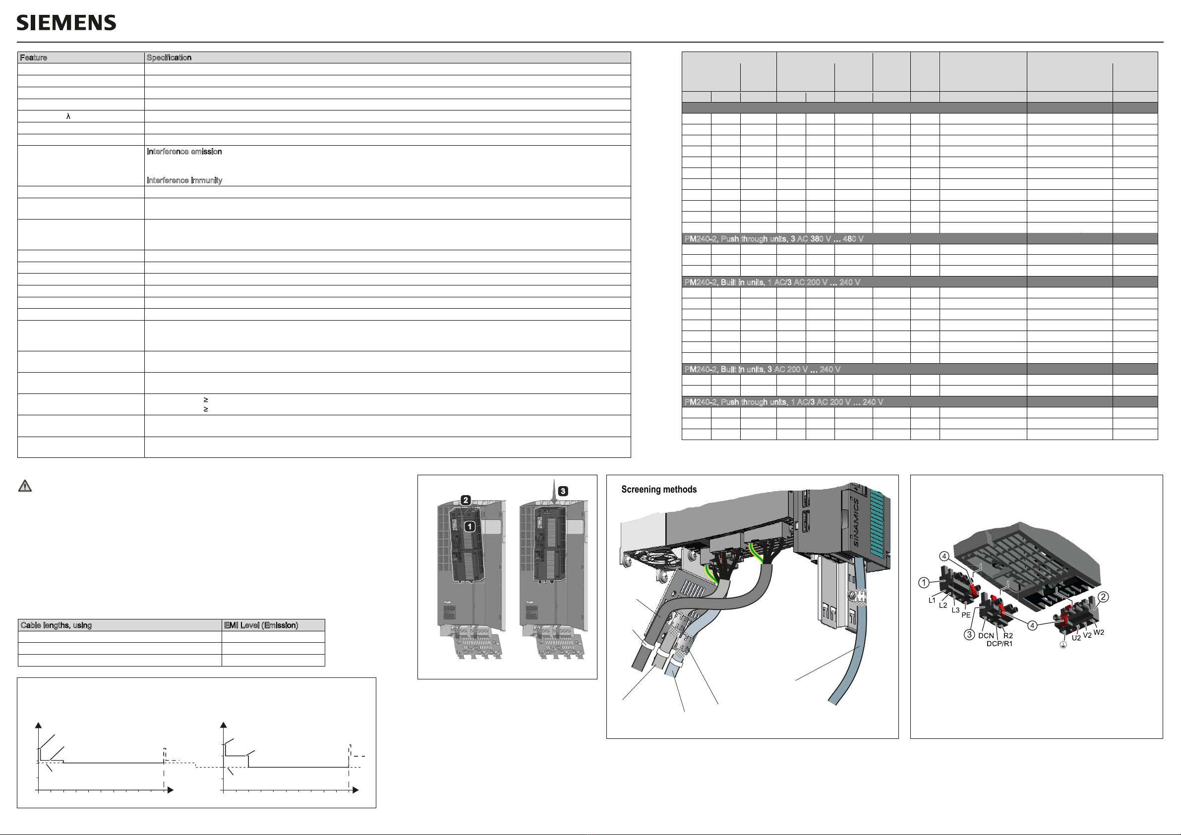
manuals.online logo
Brands
  1. Home
  2. •
  3. Brands
  4. •
  5. Siemens
  6. •
  7. Industrial Electrical
  8. •
  9. Siemens SINAMICS G120 Administrator guide

Siemens SINAMICS G120 Administrator guide

Screening plate fitting PM240-2 PT
M5,
3.5 Nm
Screening plate fitting PM240-2
Air flow distances
abovebelow
Ø 6 mm
mounting frame
fixing hole
FSC
e
e
aaa
aaa
d
c
b
mounting frame
fixing hole
mounting frame
fixing hole
mounting frame
fixing hole
Ø 6 mm
aa
aa
d
FSA/FSB
e
e
c
b
Height
Width
T1
T2
Depth
CU
IOP
Cutouts and drill patterns in
the cabinet wall for the
mounting frame
Drill patterns and dimensions PM240-2, Push Through
IP20 Units
Frame
size
Dimensions (mm)
Distances
(mm)1)
Fixings
Drill pattern
(mm)
Height
Width
Depth
Max.
depth
with CU
and OP
Above
Below
Screw
Tightening
Torque
(Nm)
a
b
c
With
Shielding
Plate
FSA
196
276
73
165
250
80
100
M4
2.5
186
62.3
6
FSB
291
370
100
165
250
80
100
M4
2.5
281
80
6
FSC
355
432
140
165
250
80
100
M4
3.0
343
120
6
1) The Power Modules can be mounted side-by-side. Due to tolerance reasons, we recommend a lateral
distance of about 1 mm
PT Units
Frame
size
Dimensions (mm)
Distances
(mm)
1)
Fixings
Drill pattern and cutouts (mm)
Height
Width
Depth
Max.
depth
with CU
and OP
Above
Below
Screw
Tightening
Torque
(Nm)
a
b
c
d
e
With
Shielding
Plate
T1
T2
FSA
238
322
126
171
117.7
53.1
256
80
100
M5
3.5
103
106
88
198
27
FSB
345
430
154
171
117.7
53.1
256
80
100
M5
3.5
147.5
134
116
304
34.5
FSC
411
500
200
171
117.7
53.1
256
80
100
M5
3.5
123
174
156
365
30.5
1) The Power Modules can be mounted side-by-side. Due to tolerance reasons, we recommend a lateral distance of about 1 mm
Cable lengths, using
EMI Level (Emission)
Screened cables, filtered units (class A)
50 m
Second Environment, C2
Screened cables, unfiltered units,
50 m
EMI Standard not fullfilled
Unscreened cables, filtered or unfiltered units
100 m
EMI Standard not fullfilled
Dimensions and drill patterns PM240-2, IP20
36.5
ac
b
FSA
a c
b
FSB/FSC
Height
Width
Depth
CU IOP
IP20 Units
Frame
size
Dimensions (mm)
Distances
(mm)1)
Fixings
Drill pattern
(mm)
Height
Width
Depth
Max.
depth
with CU
and OP
Above
Below
Screw
Tightening
Torque
(Nm)
a
b
c
With
Shielding
Plate
FSA
196
276
73
165
250
80
100
M4
2.5
186
62.3
6
FSB
291
370
100
165
250
80
100
M4
2.5
281
80
6
FSC
355
432
140
165
250
80
100
M5
3.5
343
120
6
1)
The Power Modules can be mounted side-by-side. Due to tolerance reasons, we recommend a lateral
distance of about 1 mm
PT Units
Frame
size
Dimensions (mm)
Distances
(mm)1)
Fixings
Drill patt
Height
Width
Depth
Max.
depth
with CU
and OP
Above
Below
Screw
Tightening
Torque
(Nm)
a
With
Shielding
Plate
T1
T2
FSA
238
322
126
171
117.7
53.1
256
80
100
M5
3.0
103
FSB
345
430
154
171
117.7
53.1
256
80
100
M5
3.0
147.5
FSC
411
500
200
171
117.7
53.1
256
80
100
M5
3.0
123
1) The Power Modules can be mounted side-by-side. Due to tolerance reasons, we recommend a lateral distance of about 1 mm
Cable lengths, using
EMI Level (Emission)
Screened cables, filtered units (class A)
50 m
Second Environment, C2
Screened cables, unfiltered units,
50 m
EMI Standard not fullfilled
Unscreened cables, filtered or unfiltered units
100 m
EMI Standard not fullfilled
Compact Operating Instructions SINAMICS G120
Power Module PM240-2, FSA, FSB, FSC
*A5E03701335A-08*
接触带电部件会引发生命危险
本设备会传导危险电压。
接触带电部件可能会造成人员重伤,甚至是死亡。
务必遵循变频器手册中的说明。
警告
Pericolo di morte per contatto con parti sotto tensione
In questo apparecchio sono presenti tensioni pericolose.
Il contatto con parti sotto tensione può provocare la morte o gravi lesioni.
Attenersi alle avvertenze contenute nei manuali del rispettivo convertitore.
Avvertenza
Peligro de muerte al tocar piezas bajo tensión
En el presente equipo hay aplicadas tensiones peligrosas.
Tocar piezas que están bajo tensión puede provocar lesiones corporales graves o
incluso la muerte.
Respete las indicaciones que se especifican en los manuales del convertidor
correspondiente.
Advertencia
Danger de mort en cas de contact avec des pièces sous tension
L'appareil présente des tensions électriques dangereuses.
Tout contact avec des parties sous tension peut entraîner la mort ou des blessures
graves.
Respecter les consignes figurant dans les manuels du variateur concerné.
Attention
Danger to life when live parts are touched
The present device conducts hazardous voltages.
Touching live components can result in death or severe injury.
Observe the notes in the manuals of the corresponding converter.
Warning
Lebensgefahr durch Berührung unter Spannung stehende Teile
Das vorliegende Gerät führt gefährliche Spannungen.
Beim Berühren unter Spannung stehender Teile erleiden Sie Tod oder schwere
Körperverletzungen.
Beachten Sie die Hinweise in den Handbüchern des zugehörigen Umrichters.
Warnung
Cabinet
Seal
Mounting Frame
It is recommended that the optional mounting
frame is used to install the Push-through Power
Module in a cabinet. This optional mounting
frame is designed in conjunction with the
supplied seal to easily maintain an IP55 rating of
the enclosure (the seal is delivered with the
Power Module). If the Power Module is mounted
without using the optional Mounting frame, it is
the user’s responsibility to ensure the correct IP
protection rating is reached.
FSA: 6SL3260-6AA00-0DA0
FSB: 6SL3260-6AB00-0DA0
FSC: 6SL3260-6AC00-0DA0
Push-Through mounting frame with
mounting sequence
Declaration of Conformity
The Declaration of Conformity can be found at the following link:
http://support.automation.siemens.com/WW/view/en/30563514/134200
Siemens AG,
Frauenauracher Str. 80,
DE-91056 Erlangen
Issue 09/2015
1
2
2
1
3
34
2
M4,
2.5 Nm
Insert CU Remove CU
Screening methods
Fitting CU to PM
Line
cable
Braking resistor
cable Motor cable
Control cable
Shielding brackets
Wire
straps
Compact Operating Instructions SINAMICS G120
Power Module PM240-2, FSA, FSB, FSC
Mains, Motor and Brake terminals
The Power Modules are fitted with detachable terminals. It can
be removed from the Power Module by pressing the release
catch. The connectors are not interchangeable.
Tightening torques:
FSA: 0.5 Nm ( 4 lbf.in)
FSB: 0.6 Nm ( 5 lbf.in)
FSC: 1.3 Nm (12 lbf.in)
① Mains connector
② Motor connector
③ DC Link connector
④ Release catch
Cable cross sections
FSA: 1.5 … 2.5 mm216 … 14 AWG
FSB: 1.5 … 6 mm216 … 10 AWG
FSA: 6 … 16 mm210 … 6 AWG
150 % for 3 s
110 % for 57 s
200 % for 3 s
150 % for 57 s
100 % for 240 s 100 % for 240 s
Permissible overload for operation
according „Low Overload“ (LO)
Overloads
Permissible overload for operation
according „High Overload“ (HO)
HO base load: 100 % HO power
100 % HO current
LO base load: 100 % LO power
100 % LO current
%
300240
1801200
100
200
60 t[s]
%
300240
1801200
100
150
60 t[s]
For United States / Canadian installations (UL/cUL): In order that the system is UL/cUL-compliant, use
UL/cUL-certified J-type fuses. Use 75° C copper wire only.
Additional requirements for Canadian compliance:
400 V supply:
Transient surge suppression must be installed on the line side of this equipment and shall be rated 480 V
(phase to ground), 480 V (phase to phase), suitable for overvoltage category III and shall provide protection
for a VPR maximum of 2 kV, type 1 or type 2 SPD application.
200 V supply:
Transient surge suppression must be installed on the line side of this equipment and shall be rated 240 V
(phase to ground), 240 V (phase to phase), suitable for overvoltage category III and shall provide protection
for a VPR maximum of 2 kV, type 1 or type 2 SPD application.
CAUTION - Cable cross-section for grounding: The earth cable must be at least as big as the
power cables.
Declaration of Conformity
The Declaration of Conformity can be found at the following link:
http://support.automation.siemens.com/WW/view/en/30563514/134200
Siemens AG,
Frauenauracher Str. 80,
DE-91056 Erlangen
Issue 09/2015
Cable lengths, using
EMI Level (Emission)
Screened cables, filtered units (class A)
50 m
Second Environment, C2
Screened cables, unfiltered units,
50 m
EMI Standard not fullfilled
Unscreened cables, filtered or unfiltered units
100 m
EMI Standard not fullfilled
Feature
Specification
Line voltage
3 AC 380 V … 480 V ± 10 % up to 2000 m installation
altitude. 1 AC / 3 AC 200 V ... 240 V ± 10 % up to 2000 m installation altitude.
Output voltage
3 AC 0 V … input voltage * 0.93
Input frequency
50 Hz … 60 Hz, ± 3 Hz
Output frequency
0 Hz … 550 Hz, depending on the control mode
Power factor
0.7
without line reactor; 0.85 with line reactor
Inrush current
Less than rated input current
Pulse frequency (factory setting)
4 kHz. Can be increased in 2 kHz steps up to 16 kHz. Increasing the pulse frequencies leads to an output current reduction.
Ele
ctromagnetic compatibility
Interference emission
:
The devices are suitable for second environment category C2 in accordance with IEC61800
-
3 if the following
conditions are fulfilled: The motor cable is a shielded cable with low capacitance and is not longer than 50 m. The pulse frequency does
not exceed 4 kHz, the current does not exceed the LO input value. For details, refer to the Hardware Installation Manual.
Interference immunity
:
The
devices are suitable for second environment category C
3
Braking methods
DC braking,
Compound braking, Dynamic braking with integrated chopper plus external Braking resistor
Environmental rating
Built in units
(open type equipment)
: IP20,
Push through units: IP54 / UL type 12 when mounted on a flat surface of an enclosure
Motor overload protection
This equipment is capable of providing internal motor overload protection according to UL508C. The protection level is 115
%, 230
% and
400 % full load current of the equipment. This is adjusted via parameter P640 and assumes the equipment has had basic motor
commissioning for the motor used as described in the documentation.
LO Operation temperature
1)
0 °C … 40 °C (32 °F … 104 °F) without
current
derating / up to 60 °C (140 °F) with
current
derating
HO Operati
ng temperature
1)
0 °C …
50 °C (
32
°F … 122 °F) without
current
derating / up to 60 °C (140 °F) with
current
derating
Storage temperature
-
40 °C … +70 °C (
-
40 °F … 158 °F)
Installation altitude above sea level
Up to 1000 m (3300 ft) without derating
/ Up to 4000 m (13000 ft) with derating
Humidity
< 95% RH
-
non
-
condensing
Environmental
conditions
Suitable for environmental class 3C2 according to
IEC
60721
-
3
-
3 against damaging chemical substances
Pollution
For open type equipment according
to
pollution degree level 2. Protection against conductive pollution is required e.g. using an IP54
cabinet.
For enclosed type/Push Through equipment according pollution degree level 3.
Shock
Long
-
term storage in the transport packaging according to Class
1M2 of
IEC
60721
-
3
-
1 : Transport in the transport packaging according to
Class 2M3 of IEC 60721-3-2. See Hardware Installation Manual for detailed specifications.
Vibration
Long
-
term storage in the transport packaging according to Class 1M2 to
IEC
60721
-
3
-
1 : Transport in the transport packaging according to
Class 2M3 to IEC 60721-3-2. See Hardware Installation Manual for detailed specifications.
Line impedance
200 V Units: Uk 2 %, for lower values, a line reactor must be used.
400 V Units: Uk 1 %, for lower values, a line reactor must be used.
Short Circuit Current Rating
(SCCR)
400 V units
Suitable for use on a circuit capable of delivering not more than 65 kA rms symetrical amperes; 480 Vac maximum when protecte
d by
Class J or R/C (JFHR2) semico
nductor fuses only as stated
Short Circuit Current Rating
(SCCR)
200 V units
Suitable for use on a circuit capabl
e of delivering not more than 40
kA rms symetrical amperes;
2
4
0 Vac maximum when protected by
Class J or R/C (JFHR2) semiconductor fuses only
as stated
1) according to UL, operation with temperatures > 50 °C (122 °F) is not permitted at all
LO values HO values Rated
(LO)
input
current
Frame
Size
Order No. *) Line fuses
Power Output
current
Power Output
current
kW hp A kW hp A A Siemens UL, J-type
PM240-2, Built in units, 3 AC 380 V … 480 V
0.55
0.75
1.7
0.37
0.50
1.3
2.3
FSA
6SL3210
-
1PE11
-
8_L1
3NA3 804
(4 A)
10
A
0.75
1.00
2.2
0.55
0.75
1.7
2.9
FSA
6SL3210
-
1PE12
-
3_L1
3N A3 804
(4 A)
10
A
1.10
1.50
3.1
0.75
1.00
2.2
4.1
FSA
6SL3210
-
1PE13
-
2_L1
3N A3 801
(6 A)
15
A
1.50
2.00
4.1
1.10
1.50
3.1
5.5
FSA
6SL3210
-
1PE14
-
3_L1
3N A3 803
(10 A)
20
A
2.20
3.00
5.9
1.50
2.00
4.1
7.7
FSA
6SL3210
-
1PE16
-
1_L1
3N A3 803
(10 A)
30
A
3.00
4.00
7.7
2.20
3.00
5.9
10.1
FSA
6SL3210
-
1PE18
-
0_L1
3N
A3 805
(16 A)
30
A
4.00
5.00
10.2
3.00
4.00
7.7
13.3
FSB
6SL3210
-
1PE21
-
1_L0
3NE 1814
-
0
(20 A)
35
A
5.50
7.50
13.2
4.00
5.00
10.2
17.2
FSB
6SL3210
-
1PE21
-
4_L0
3NE 1815
-
0
(25 A)
35
A
7.50
10.00
18.0
5.50
7.50
13.2
22.2
FSB
6SL3210
-
1PE21
-
8_L0
3NE 1803
-
0
(35
A)
35 A
11.00
15,00
26.0
7.50
10.00
18.0
32.6
FSC
6SL3210
-
1PE22
-
7_L0
3NE 1817
-
0
(50 A)
50 A
15.00
20.00
32.0
11.00
15.00
26.0
39.9
FSC
6SL3210
-
1PE23
-
3_L0
3NE 1817
-
0
(50 A)
50 A
PM240
-
2, Push through units, 3 AC 380 V … 480 V
3.00
4.00
7.7
2.20
3.00
5.9
10.1
FSA
6SL3211
-
1PE18
-
0_L1
3N A3 805
(16 A)
30
A
7.50
10.00
18.0
5.50
7.50
13.2
22.2
FSB
6SL3211
-
1PE21
-
8_L0
3NE 1803
-
0
(35 A)
35
A
15.00
20.00
32.0
11.00
15.00
26.0
39.9
FSC
6SL3211
-
1PE23
-
3_L0
3NE 1817
-
0
(50 A)
50 A
PM240
-
2, Built in units, 1 AC
/3 AC
200 V … 240 V
0.55
0.75
3.
2
0.37
0.50
2.3
7.5
FSA
6SL3210
-
1PB13
-
0_L0
3NA3 803
(10 A)
15
A
0.75
1.00
4.2
0.55
0.75
3.2
9.6
FSA
6SL3210
-
1PB13
-
8_L0
3NA3 805
(16 A)
15 A
1.10
1.50
6
0.75
1.00
4.2
13.5
FSB
6SL3210
-
1PB15
-
5_L0
3NE 1814
-
0
(20 A)
35
A
1.50
2.00
7.4
1.10
1.50
6
18.1
FSB
6SL3210
-
1PB17
-
4_L0
3NE 1815
-
0
(25 A)
35
A
2.20
3.00
10.4
1.50
2.00
7.4
24.0
FSB
6SL3210
-
1PB21
-
0_L0
3NE 1803
-
0
(35 A)
35 A
3.00
4.00
13.6
2.20
3.00
10.4
35.9
FSC
6SL3210
-
1PB21
-
4_L0
3NE 1817
-
0
(50 A)
5
0
A
4.00
5.00
17.5
3.00
4.00
13.6
43.0
FSC
6SL3210
-
1PB21
-
8_L0
3NE 1818
-
0
(63 A)
5
0 A
PM240
-
2, Built in units, 3 AC 200 V … 240 V
5.50
7.50
22.0
4.00
5.00
17.5
29.0
FSC
6SL3210
-
1PC22
-
2_L0
3NE
1802
-
0
(40A)
5
0
A
7.50
10.00
28.0
5.50
7.50
22.0
37.0
FSC
6SL3210
-
1PC22
-
8_L0
3NE 1817
-
0
(50A)
50
A
PM240
-
2, Push through units, 1 AC
/3 AC
200 V … 240 V
0.75
1.00
4.2
0.55
0.75
3.2
9.6
FSA
6SL3211
-
1PB13
-
8_L0
3NA3 805
(16 A)
15 A
2.20
3.00
10.4
1.50
2.00
7.4
24.0
FSB
6SL3211
-
1PB21
-
0_L0
3NE 1803
-
0
(35 A)
35 A
4.00
5.00
17.5
3.00
4.00
13.6
43.0
FSC
6SL3211
-
1PB21
-
8_L0
3NE 1818
-
0
(63 A)
5
0 A
*) _
: A = filtered unit, U = unfiltered unit

Other manuals for SINAMICS G120

52

This manual suits for next models

4

Other Siemens Industrial Electrical manuals

Siemens 7XR6004 Series Manual

Siemens

Siemens 7XR6004 Series Manual

Siemens SIMATIC RTLS User manual

Siemens

Siemens SIMATIC RTLS User manual

Siemens SINAMICS S120 User manual

Siemens

Siemens SINAMICS S120 User manual

Siemens 3VA921-0JC22 Series User manual

Siemens

Siemens 3VA921-0JC22 Series User manual

Siemens BD01 Series User manual

Siemens

Siemens BD01 Series User manual

Siemens 3VA94-0KP00 Series User manual

Siemens

Siemens 3VA94-0KP00 Series User manual

Siemens SIRIUS S00 User manual

Siemens

Siemens SIRIUS S00 User manual

Siemens SIPLUS HCS4 00 Series Quick guide

Siemens

Siemens SIPLUS HCS4 00 Series Quick guide

Siemens HM656A User manual

Siemens

Siemens HM656A User manual

Siemens ASR Series User manual

Siemens

Siemens ASR Series User manual

Siemens COMBIMASTER User manual

Siemens

Siemens COMBIMASTER User manual

Siemens Sivacon S8 User manual

Siemens

Siemens Sivacon S8 User manual

Siemens BD01-GK User manual

Siemens

Siemens BD01-GK User manual

Siemens FDMH291 Series User manual

Siemens

Siemens FDMH291 Series User manual

Siemens 3VA1 Series User manual

Siemens

Siemens 3VA1 Series User manual

Siemens FDCL181 User manual

Siemens

Siemens FDCL181 User manual

Siemens MICROMASTER 440 Operating and maintenance instructions

Siemens

Siemens MICROMASTER 440 Operating and maintenance instructions

Siemens SIRIUS 3RA131 8XB Series User manual

Siemens

Siemens SIRIUS 3RA131 8XB Series User manual

Siemens 3VA9277-0FK2 Series User manual

Siemens

Siemens 3VA9277-0FK2 Series User manual

Siemens SIRIUS 8WD44 User manual

Siemens

Siemens SIRIUS 8WD44 User manual

Siemens Simatic S7-1500 Technical Document

Siemens

Siemens Simatic S7-1500 Technical Document

Siemens SENTRON SUPERSWITCH 3KL82 Series User manual

Siemens

Siemens SENTRON SUPERSWITCH 3KL82 Series User manual

Siemens Gigaset S2 Professional User manual

Siemens

Siemens Gigaset S2 Professional User manual

Siemens SIRIUS 3RV19 Series User manual

Siemens

Siemens SIRIUS 3RV19 Series User manual

Popular Industrial Electrical manuals by other brands

WEG FSW 160 manual

WEG

WEG FSW 160 manual

Eaton EZ installation instructions

Eaton

Eaton EZ installation instructions

Murata LLA215R71E223MA14 Series Reference sheet

Murata

Murata LLA215R71E223MA14 Series Reference sheet

Murata GRT155R61C224ME01 Series Reference sheet

Murata

Murata GRT155R61C224ME01 Series Reference sheet

American Innovations MicroMax GPS300 user guide

American Innovations

American Innovations MicroMax GPS300 user guide

Murata GRM1887U1H242JA01 Series Reference sheet

Murata

Murata GRM1887U1H242JA01 Series Reference sheet

Murata GRM0335C1H7R3DA01 Series Reference sheet

Murata

Murata GRM0335C1H7R3DA01 Series Reference sheet

Murata GRM0335C1ER10WA01 Series Reference sheet

Murata

Murata GRM0335C1ER10WA01 Series Reference sheet

Eaton DILM65-XIP2X installation instructions

Eaton

Eaton DILM65-XIP2X installation instructions

Murata GRM0335C1H7R2BA01 Series Reference sheet

Murata

Murata GRM0335C1H7R2BA01 Series Reference sheet

ABB PCS100 AVC-40-1B Accessories assembly instructions

ABB

ABB PCS100 AVC-40-1B Accessories assembly instructions

Murata GRM1555C1H361GA01 Series Reference sheet

Murata

Murata GRM1555C1H361GA01 Series Reference sheet

Murata GJM0335C1E2R0BB01 Series Reference sheet

Murata

Murata GJM0335C1E2R0BB01 Series Reference sheet

Murata GRM0225C1E7R1CA03 Series Reference sheet

Murata

Murata GRM0225C1E7R1CA03 Series Reference sheet

Murata GCM1885C1H361JA16 Series Reference sheet

Murata

Murata GCM1885C1H361JA16 Series Reference sheet

DX Engineering DXE-AAPS3-1P manual

DX Engineering

DX Engineering DXE-AAPS3-1P manual

Murata GRM1555C2A7R9DA01 Series Reference sheet

Murata

Murata GRM1555C2A7R9DA01 Series Reference sheet

Eaton FIP-XHI11 Instruction leaflet

Eaton

Eaton FIP-XHI11 Instruction leaflet

manuals.online logo
manuals.online logoBrands
  • About & Mission
  • Contact us
  • Privacy Policy
  • Terms and Conditions

Copyright 2025 Manuals.Online. All Rights Reserved.