manuals.online logo
Brands
  1. Home
  2. •
  3. Brands
  4. •
  5. Siemens
  6. •
  7. Security Sensor
  8. •
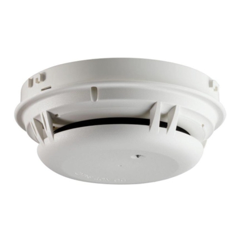
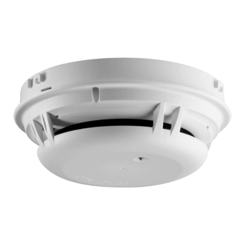
  9. Siemens DB-11 Instruction Manual

Siemens DB-11 Instruction Manual

Figure 3 Wiring Diagram for DB-11/-11E using HFP-11 and HFPT-11 Detectors
Model DB-11/-11E
(P/N 500-094151/500-094151E)
Siemens Building Technologies, Inc.
8 Fernwood Road
Florham Park, New Jersey 0 932
Siemens Building Technologies, Ltd.
2 Kenview Boulevard
Brampton, Ontario, Canada L6T 5E4
Figure 2 Wiring Diagram for DB-11/-11E using FP-11, FPT-11, FS-DP, FS-DPT, and FS-DT Detectors
1a6
---
----
++++ +++
TO INITIATING
CIRCUIT OF
SBT, INC.
COMPATIBLE
CONTROL UNIT
OPTIONAL
REMOTE
ALARM
INDICATOR
MODELS
RLI-1 / RLI-2
TO NEXT BASE
TO NEXT BASE
DO NOT
USE AN
END OF
LINE
DEVICE
DB-11/-11E (NO REMOTE DEVICE)
5
6
1a
1b
5
6
1a
1b
RELAY*
CONTACTS
3A, 120 VAC
3A, 30 VDC
DB-11XRS (REMOTE RELAY BASE)
*The relay contacts are shown in the Non-Alarm/System Reset condition.
5+
NO
C
NC
6–
5+
NO
C
NC
6–
DO NOT
USE AN
END OF
LINE
DEVICE
TO INITIATING
CIRCUIT OF
SBT, INC.
COMPATIBLE
CONTROL UNIT
OPTIONAL
REMOTE
ALARM
INDICATOR
MODELS
RL-HW / RL-HC
TO NEXT BASE
TO NEXT BASE
DO NOT
USE AN
END OF
LINE
DEVICE
DB-11/-11E (NO REMOTE DEVICE)
LINE 1**
LINE 2**
TB1
TB3
TB2
5
6
1a
1b
5
6
1a
1b
RELAY*
CONTACTS
3A, 120 VAC
3A, 30 VDC
DB-HR (REMOTE RELAY BASE)
*The relay contacts are shown in the Non-Alarm/System Reset condition.
**HFP-11/HFPT-11 is a polarity insensitive detector. Line 1 and Line 2 can be either line of the loop.
5+
NO
C
NC
6–
5+
NO
C
NC
6–
DO NOT
USE AN
END OF
LINE
DEVICE
Figure 1 Wiring Diagram for DB-11/-11E using PE-11, PE-11T, and DT-11 Detectors
CAUTION:
1. Do not use looped wire under base terminal 5. Break wire
run to provide supervision o connection.
2. When a remote relay is used to control a critical system
unction, the relay and its associated detector and optional
module(s) must be the ONLY devices on the initiating circuit.
Installation/Wiring Instructions
MODEL DB-11/-11E DETECTOR BASE
Fire Safety
1b
6
5
END OF LINE DEVICE
(NOTE POLARITY
WHEN APPLICABLE)
1a 1b
1b
5
5
6
+
-
+
-
(SEE CAUTION 1)
MULTIPLE REMOTE DEVICES
If remote devices are supported by the initiating circuit, each detector/base may
have up to 2 remote devices with the following configurations and restrictions only:
Remote
Device 1
RR-11
RR-11
RLC-11, RLW-11
RLC-11, RLW-11
Remote
Device 2
RLC-11, RLW-11
RSAC-11, RSAW-11
RSAC-11, RSAW-11
RLC-11, RLW-11
Restrictions
See Caution 2
See Caution 2
Wire from base to
RSAC-11/RSAW-11 to RL-11
SEE REMOTE DEVICE INSTRUCTIONS FOR WIRING DETAILS:
DEVICE
RR-11
RLC-11, RLW-11
RSAC-11, RSAW-11
INSTALLATION
INSTRUCTIONS
P/N 315-094924
P/N 315-094925
P/N 315-094926
TO INITIATING
CIRCUIT OF
SBT, INC.
COMPATIBLE
CONTROL UNIT
DB-11/-11E (NO REMOTE DEVICE) DB-HR (REMOTE RELAY BASE)
DETECTOR AND BASE PLACEMENT
Detector and base locations shall follow the drawings
provided or approved by Siemens Building Technologies, Inc.
or its authorized distributors. This is extremely important! The
detector placements shown on these drawings were chosen
after a careful evaluation of all facets of the protected area.
When drawings are not available, refer to Detector Placement
section of detector Installation/Wiring Instructions and to
NFPA Standard 2 and CAN/ULC-S524.
BASE WIRING
Siemens Building Technologies, Inc.'s detectors should be
interconnected as shown in Figures 1, 2 or 3 and wired
to the control panel following the wiring connection drawing
installed on the inside face of each control panel cover. NOTE:
H Series devices are wired to the DLC (refer to DLC
Installation Instructions, P/N 315-033090.) Note any
limitations on the number of detectors and restrictions on
the use of remote devices permitted for each circuit.
DETECTOR MOUNTING USING THE DB-11/-11E BASE
The detector is provided with a separate base which attaches
to a standard 4 inch square, 4 inch octagonal, or single gang
electrical box, with the box size and depth required by the
NEC for the number and size of conductors used. Wire size:
max  14 AWG, min  18 AWG.
Installation Instru tions P/N 315-094193-7
Model DB-11/-11E
(P/N 500-094151/500-094151E)
Figure 4
Mounting The DB-11 Base
Siemens Building Technologies, Inc.
8 Fernwood Road
Florham Park, New Jersey 0 932
Siemens Building Technologies, Ltd.
2 Kenview Boulevard
Brampton, Ontario, Canada L6T 5E4
BASE
MOUNTING
HOLES
MOUNTING
HOLE COVERS
USE DBJ-11 JUMPER
KIT, P/N 500-699167
FOR CONTINUITY
CHECK WITH PE-11,
PE-11T OR DT-11
DETECTORS
ALARM LED
LOCATION WITH
DETECTOR
INSTALLED
IN BASE
6
5
1a
1b
D
O
N
O
T
P
A
I
N
T
FACTORY
INSTALLED
JUMPER
BASE
MOUNTING
HOLE
ALARM LED
LOCATION WITH
DETECTOR
INSTALLED
IN BASE
Figure 5
Mounting The DB-11E Base
Refer to Figures 4 and 5, as applicable.
1. Route all wires outward from outlet box.
2. When ALARM LED viewing is critical, position the LED mark in the base in the intended direction.
3. Route wires through the hole in the center of the base and mount base to outlet box. Make connections
directly to the base terminals. Refer to Figures 1, 2 and 3 for details.
4. After all bases are installed, check loop continuity. Refer to the System Manual for the loop continuity check
procedure. To allow for the continuity check with PE-11, PE-11T or DT-11 detectors, use DBJ-11 Jumper Kit, P/N
500-69916 (between terminals 1a and 1b) to complete the loop. Do not use a jumper for FP-11/HFP-11/FS
family devices.
5. Continuity jumper must be removed from each base prior to installing detector.
6. To insure proper installation of the detector head into the base:
a. Route wires away from connector terminals.
b. Take up all slack in the outlet box.
c. Properly dress and position all wires flat against the base.
d. Check that screw terminals are tight.
. (DB-11 only) Break off the two mounting hole covers, and insert in two outer base mounting holes.
This manual suits for next models

1

Other Siemens Security Sensor manuals

Siemens FDOOT221 User manual

Siemens

Siemens FDOOT221 User manual

Siemens AD-3I User manual

Siemens

Siemens AD-3I User manual

Siemens S7-1500F User manual

Siemens

Siemens S7-1500F User manual

Siemens DB110 User manual

Siemens

Siemens DB110 User manual

Siemens GAMMA instabus AP 251/11 Service manual

Siemens

Siemens GAMMA instabus AP 251/11 Service manual

Siemens ADM-Q12T User manual

Siemens

Siemens ADM-Q12T User manual

Siemens FDT181 User manual

Siemens

Siemens FDT181 User manual

Siemens 5SM6 01 2 Series User manual

Siemens

Siemens 5SM6 01 2 Series User manual

Siemens LAE10 User manual

Siemens

Siemens LAE10 User manual

Siemens Cerberus CS1140 Guide

Siemens

Siemens Cerberus CS1140 Guide

Siemens IS404 User manual

Siemens

Siemens IS404 User manual

Siemens FDF241-9 User manual

Siemens

Siemens FDF241-9 User manual

Siemens FDBH291 User manual

Siemens

Siemens FDBH291 User manual

Siemens SICAM V01.00 User manual

Siemens

Siemens SICAM V01.00 User manual

Siemens FS20 Technical manual

Siemens

Siemens FS20 Technical manual

Siemens GM730 User manual

Siemens

Siemens GM730 User manual

Siemens FS720 Series User manual

Siemens

Siemens FS720 Series User manual

Siemens DB721 User manual

Siemens

Siemens DB721 User manual

Siemens QRI Series User manual

Siemens

Siemens QRI Series User manual

Siemens DELTA i-system 1,1 Komfort 5TC1 505 User manual

Siemens

Siemens DELTA i-system 1,1 Komfort 5TC1 505 User manual

Siemens FDM243H User manual

Siemens

Siemens FDM243H User manual

Siemens DF11 Series User manual

Siemens

Siemens DF11 Series User manual

Siemens 5SV60 MC Series User manual

Siemens

Siemens 5SV60 MC Series User manual

Siemens Matchtec IRM270C User manual

Siemens

Siemens Matchtec IRM270C User manual

Popular Security Sensor manuals by other brands

SubSurface Instruments AML Operator's manual

SubSurface Instruments

SubSurface Instruments AML Operator's manual

Levenhuk ERMENRICH PING SD20 user manual

Levenhuk

Levenhuk ERMENRICH PING SD20 user manual

Halma SENSITRON SMART3G-GrI manual

Halma

Halma SENSITRON SMART3G-GrI manual

DSC AMB-300 installation instructions

DSC

DSC AMB-300 installation instructions

ARROWELD RADIOACTIVITY user manual

ARROWELD

ARROWELD RADIOACTIVITY user manual

aidapt VM909B instructions

aidapt

aidapt VM909B instructions

Datalogic S85 quick start guide

Datalogic

Datalogic S85 quick start guide

dtec GJD 350 Installation & setup guide

dtec

dtec GJD 350 Installation & setup guide

Panasonic Firetracker FT128 Operation manual

Panasonic

Panasonic Firetracker FT128 Operation manual

Bacharach 6401-0500 Installation and operation manual

Bacharach

Bacharach 6401-0500 Installation and operation manual

DOEPFER A-100 Series manual

DOEPFER

DOEPFER A-100 Series manual

Bosch VMD01 M50 PAL operating instructions

Bosch

Bosch VMD01 M50 PAL operating instructions

jablotron JA-88P manual

jablotron

jablotron JA-88P manual

CMC Rescue Multi-Purpose Device 333010-CE manual

CMC Rescue

CMC Rescue Multi-Purpose Device 333010-CE manual

BEA IXIO-DT1 manual

BEA

BEA IXIO-DT1 manual

PCWI DC15 Operator's handbook

PCWI

PCWI DC15 Operator's handbook

3M 8516 user guide

3M

3M 8516 user guide

Sperian MILLER MIGHTEVAC User instruction manual

Sperian

Sperian MILLER MIGHTEVAC User instruction manual

manuals.online logo
manuals.online logoBrands
  • About & Mission
  • Contact us
  • Privacy Policy
  • Terms and Conditions

Copyright 2025 Manuals.Online. All Rights Reserved.