manuals.online logo
Brands
  1. Home
  2. •
  3. Brands
  4. •
  5. Siemens
  6. •
  7. Security Sensor
  8. •
  9. Siemens RAR Series User manual

Siemens RAR Series User manual

CC1N7713en
30.08.2010
Building Technologies Division
Industry Sector
7713
Photocell Detectors RAR...
The photocell detectors are designed for use with burner controls, for the super-
vision of yellow-flame oil flames.
They are used especially in connection with burner controls for the control and
supervision of large-capacity burners.
The RAR... and this Data Sheet are intended for use by OEMs which integrate the
flame detectors in their products!
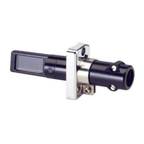
Use The RAR... flame detectors are used for the supervision of yellow-burning oil flames.
They are designed for use with the following types of burner controls: LAL..., LAE1...,
LOK16... and LAE10...
2/4
Building Technologies Division CC1N7713en
Industry Sector 30.08.2010
Warning notes
To avoid injury to persons, damage to property or the environment, the following
warning notes must be observed!
Do not open, interfere with or modify the flame detector!
•All activities (mounting, installation and service work, etc.) must be performed by
qualified staff
•Before making any wiring changes in the connection area, completely isolate the
plant from mains supply (all-polar disconnection). Ensure that the plant cannot be
inadvertently switched on again and that it is indeed dead. If not observed, there is
a risk of electric shock hazard
•Ensure protection against electric shock hazard by providing adequate protection
for the connection terminals. If this is not observed, there is a risk of electric shock
•Each time work has been carried out (mounting, installation, service work, etc.),
check to ensure that wiring is in an orderly state. If this is not observed, there is a
risk of loss of safety functions and a risk of electric shock
•Fall or shock can adversely affect the safety functions. Such flame detectors or
burner controls must not be put into operation, even if they do not exhibit any dam-
age. If this is not observed, there is a risk of loss of safety functions and a risk
of electric shock
Mounting notes
•Ensure that the relevant national safety regulations are complied with
•The flame detector plugs into the burner (the detector’s clamp engages on the
burner’s light metal flange)
Installation notes
•Always run the high-voltage ignition cables separate from the unit and other cables
while observing the greatest possible distances
Electrical connection of the flame detector
It is important to achieve practically disturbance- and loss-free signal transmission:
•Never run the detector cable together with other cables
– Line capacitance reduces the magnitude of the flame signal
– Use a separate cable
•Observe the permissible detector cable lengths (refer to «Type summary»)
Commissioning notes
•The intensity of light radiation on site is checked by measuring the detector current
22 24
22 24
910
1314
LAL2.../LAL3...
LOK16...
LAE1...
LAE10...
-+
M
RAR
-
+
7713v01/9512
A
A Incidence of light
M Microammeter (DC), internal resistance 5,000 Ω
For the minimum detector currents required, refer to the Data Sheet of the relevant
burner control.
Measuring circuit for
measuring the detector
current
Legend
3/4
Building Technologies Division CC1N7713en
Industry Sector 30.08.2010
Standards and certificates
Conformity to EEC directives
- Electromagnetic compatibility EMC (immunity)
- Low-voltage directive
2004/108/EC
2006/95/EC
ISO 9001: 2010
Cert. 00739 ISO 14001: 2010
Cert. 38233
Service notes
•Each time a unit has been replaced, check to ensure that wiring is in an orderly
state and that the wires are firmly connected
Disposal notes The flame detector contains electrical and electronic components and must not be dis-
posed of together with household waste.
Local and currently valid legislation must be observed.
Mechanical design
- Housing made of dust-proof duroplast
- Photocell is under protective glass
- Flame detector can be supplied with or without flange (version 4 241 8855 0) and
clamp (refer to «Type summary»)
Type summary
Type
reference Length of
detector cable Clamp and flange Photocell made of
RAR9 max. 100 m Without clamp / flange Silicon
RAR9(1) max. 100 m With clamp and flange with radius Silicon
RAR9(2) max. 100 m With clamp and flange straight Silicon
When ordering, please give the type reference according to «Type summary».
Accessories
Item Part number
Flange with radius 4 241 8855 0
Flange straight 4 241 8898 0
Clamp 4 199 8806 0
Type reference Description
AGG09
IP40 Kit for RAR...
- Cable sealing element Ø 5...8 mm
Only in connection with
the burner control
4/4
Building Technologies Division CC1N7713en
Industry Sector 30.08.2010
Technical data Safety class II
Degree of protection IP20
&Note!
IP40 to DIN EN 60529, at relative
design of cable entry (e.g. AGG09)
Mounting position optional
Weight approx. 85 g
Cable connection Screw terminals for min. 0.5 mm² and max.
1,5 mm² wire cross section
Cable with ferrules
A
dapt at stranded wire cross section
Storage DIN EN 60 721-3-1
Climatic conditions class 1K3
Mechanical conditions class 1M2
Temperature range -20...+60 °C
Humidity < 95 % r.F.
Transport DIN EN 60 721-3-2
Climatic conditions class 2K2
Mechanical conditions class 2M2
Temperature range -20...+60 °C
Humidity < 95 % r.h.
Operation DIN EN 60 721-3-3
Climatic conditions class 3K5
Mechanical conditions class 3M2
Temperature range -20...+60 °C
Humidity < 95 % r.h.
Warning!
Condensation, formation of ice and ingress of water are not permitted!
Function With this type of flame supervision, the radiation of oil flames in the visible band of the
light spectrum is used for generating the flame signal.
The light-sensitive element is a photocell. When illuminated, it generates DC voltage,
causing a current to flow to the input of the flame signal amplifier. Hence, the RAR... is
an active detector.
The photocell is insensitive to infrared radiation so that glowing firebrick in the combus-
tion chamber cannot produce a flame signal.
Dimensions Dimensions in mm
130
49...73 2,5
30
48 18
ø23
18
ø22,5
M4
7713m01/0597
10
General data
Environmental
conditions
©2010 Siemens AG Industry Sector Building Technologies Division
Subject to change!

This manual suits for next models

3

Other Siemens Security Sensor manuals

Siemens ELP 319 Service manual

Siemens

Siemens ELP 319 Service manual

Siemens Cerebrus Pyrotronics SA-11P User manual

Siemens

Siemens Cerebrus Pyrotronics SA-11P User manual

Siemens SLD4 Supplement

Siemens

Siemens SLD4 Supplement

Siemens DB-HR User manual

Siemens

Siemens DB-HR User manual

Siemens FDO421 User manual

Siemens

Siemens FDO421 User manual

Siemens SIMATIC ET 200S User manual

Siemens

Siemens SIMATIC ET 200S User manual

Siemens FDOOTC241 User manual

Siemens

Siemens FDOOTC241 User manual

Siemens QBM4000 Series User manual

Siemens

Siemens QBM4000 Series User manual

Siemens HI921 User manual

Siemens

Siemens HI921 User manual

Siemens FDB22 Series User manual

Siemens

Siemens FDB22 Series User manual

Siemens SO320 User manual

Siemens

Siemens SO320 User manual

Siemens SA-3I User manual

Siemens

Siemens SA-3I User manual

Siemens 5TC1585 User manual

Siemens

Siemens 5TC1585 User manual

Siemens DF11 Series User manual

Siemens

Siemens DF11 Series User manual

Siemens AZL66 Series User manual

Siemens

Siemens AZL66 Series User manual

Siemens FDOOTC241 User manual

Siemens

Siemens FDOOTC241 User manual

Siemens FDB181 Series User manual

Siemens

Siemens FDB181 Series User manual

Siemens GAMMA instabus AP 251/11 Service manual

Siemens

Siemens GAMMA instabus AP 251/11 Service manual

Siemens CEREBRUS PYROTRONICS AD-3XRI User manual

Siemens

Siemens CEREBRUS PYROTRONICS AD-3XRI User manual

Siemens 5SV6 User manual

Siemens

Siemens 5SV6 User manual

Siemens AS Series User manual

Siemens

Siemens AS Series User manual

Siemens QRI Series User manual

Siemens

Siemens QRI Series User manual

Siemens DB721 User manual

Siemens

Siemens DB721 User manual

Siemens IS404 User manual

Siemens

Siemens IS404 User manual

Popular Security Sensor manuals by other brands

Aritech 2000 Series Installation sheet

Aritech

Aritech 2000 Series Installation sheet

RS PRO 796-2053 quick start guide

RS PRO

RS PRO 796-2053 quick start guide

Skil 0550 instructions

Skil

Skil 0550 instructions

Guardian Fall Protection User instruction manual

Guardian

Guardian Fall Protection User instruction manual

MRC XY4QD user manual

MRC

MRC XY4QD user manual

Satel GRAPHITE quick start guide

Satel

Satel GRAPHITE quick start guide

Bacharach MGS-150 Installation and operation manual

Bacharach

Bacharach MGS-150 Installation and operation manual

Global Fire Equipment GFE-H Installation

Global Fire Equipment

Global Fire Equipment GFE-H Installation

resideo Honeywell Home PROA7 Series user guide

resideo

resideo Honeywell Home PROA7 Series user guide

MSA FireHawk M7XT Operation and instructions

MSA

MSA FireHawk M7XT Operation and instructions

Perenio PECMS01 quick start guide

Perenio

Perenio PECMS01 quick start guide

IGD TOC-750 Series Operation manual

IGD

IGD TOC-750 Series Operation manual

CUGGL EXTRA WIDE HALLWAY GATE manual

CUGGL

CUGGL EXTRA WIDE HALLWAY GATE manual

delight 18695 user manual

delight

delight 18695 user manual

Dahua Technology ARD323-W2 user manual

Dahua Technology

Dahua Technology ARD323-W2 user manual

Texecom AED-0009 quick start guide

Texecom

Texecom AED-0009 quick start guide

Ecolink Firefighter CS-600 Installation manual & users guide

Ecolink

Ecolink Firefighter CS-600 Installation manual & users guide

AccuBANKER LED440 user guide

AccuBANKER

AccuBANKER LED440 user guide

manuals.online logo
manuals.online logoBrands
  • About & Mission
  • Contact us
  • Privacy Policy
  • Terms and Conditions

Copyright 2025 Manuals.Online. All Rights Reserved.