manuals.online logo
Brands
  1. Home
  2. •
  3. Brands
  4. •
  5. Siemens
  6. •
  7. Switch
  8. •
  9. Siemens MBKBC3 User manual

Siemens MBKBC3 User manual

s
S1, S2, and P1 Panelboard Kit
MBKBC3 for Main or Subfeed
BQD breakers
Installation
Instructions
12-A-1011-01 Rev. 5
CENTER OF
KNOCKOUT
PLATE
FRONT OF
DEADFRONT
GRASP DEADFRONT
IN THIS AREA
DEAD FRONT KNOCKOUT REMOVAL INSTRUCTIONS
11. Stand the deadfront on the floor with the plate to be
removed in the upper position as shown below.
Grasping the upper edge of the deadfront, strike the
center of the front surface of the knockout plate with a
hammer until two of the plate attachment splices are
broken.
12. Bend the plate back-and-forth about the two remain-
ing attachments until the plate breaks free.
FLOOR
-4-
Installation Instructions
1. For installation as a main breaker (250A and lower
panels only). Lock off all power supplying this
equipment before working on it. To install this kit as a
main breaker, remove the deadfront and main lugs if
installed. Place the main breaker connector assembly
(Item 2) so that the ends of the assembly with the half
holes are positioned under the section or main bus.
Fasten to the main bus using the 1/4-20 hex head
SEMS assembly machine screws (Item 8) provided.
Take care to see that the half hole engages the anti-
turn tab on the underside of the section bus. DO NOT
TIGHTEN AT THIS TIME.
2. Attach the breaker support (Item 1) and the BQCH
support barrier (Item 10) to the base rail using (2) of
the #10-32 slotted hex washer head thread forming
screws (Item 6) provided as shown on page 2.
3. Position the breaker on the breaker support (Item 1)
and attach to the connector assembly using the
#10-32 slotted hex head SEMS assembly machine
screws (Item 7) provided.
4. Torque all connections to the values specified on the
installation and maintenance instruction label affixed
to the rear of the deadfront.
5. Attach the main or branch cables to the breaker and
torque connections to the values specified on the
device, or if no values are specified on the device,
refer to the installation and maintenace instructions
affixed to the rear of the deadfront of the panel.
6. Remove the insert plate installed in any deadfront
opening in the area that will cover this kit. If there is
no opening, follow the instructions on page 4 to
remove the main/ subfeed knockout. Install the cover
plate (Item 3) provided with this kit into the front of the
dead front as shown by inserting two plate edge tabs
into one edge of the cutout and then snapping the
other two tabs in place. For main breaker applica-
tions, apply the "MAIN" label (Item 4) to the cover
plate (Item 3) as shown.
7. On 4 wire systems the neutral lug (Item 5) is required.
The neutral lug assembly comes in the kit ready to
assemble on the upper right or the lower left position
of the neutral bus (Note Neutral positions shown on
the instructional drawing). If it is desirable to place
the lug at the other corners of the panel, the lug may
be disassembled and the lug pad flipped 180 degrees
and re-assembled. See instructional drawing below.
Follow the torque values specified on the installation
and maintenance label. The lug may be attached to
the neutral cross bar at any open corner using the
#10-24 slotted hex head thread forming screws (Item
9) provided. Again, follow the torque values specified
on the installation and maintenance label.
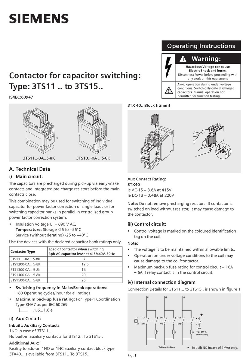
The following instructions are for the installation of a Siemens main/subfeed breaker kit for BDQ breakers in S1, S2, and P1
Type panelboards. The kit may be installed as a main or a subfeed in panels rated 250 amps or less. Above 250 amps it
may be installed in subfeed applications only. The parts provided in this kit are for connection to a 3 phase 3 or 4 wire
system. The breaker is not included with this kit and must be purchased separately. Be sure to choose the appropriate
breaker for the system in use. For 3 wire systems, disregard the neutral connection.
12-A-1011-01 Rev. 5
-3--2-
DANGER
Hazardous voltage.
Will cause death or
serious injury.
Keep out.
Qualified personnel only.
Disconnect and lock off all
power before working on
this equipment.
8. Before energizing the panel, ensure that all connec-
tions have been torqued and that the deadfront is
installed.
9. Installation as a subfeed breaker. Follow steps (1)
through (8) except that any subfeed breakers or feed
thru lugs assemblies existing in the panel are
removed. In addition, do not install the "MAIN" label.
10. In panels rated higher than 250A, kits mount only at
the end of the interior designated for subfeeds. See
reference drawing below. Kit connectors fasten to the
end holes in the panel phase bus, the breaker
support fastens to the two base rail holes nearest the
deadfront support, and the neutral lug, if installed,
fastens to the diagonal hole pattern on the neutral lug
pad.
NEUTRAL LUG DETAIL
400A P1 PANELBOARD INTERIOR
MAIN
END
SUB-FEED
END
Neutral cross bar
Neutral lug position
Base rail
Deadfront support
Neutral lug position
3
4
7
2
5
9
6
8
1
10
ITEM DESCRIPTION QTY
1 BREAKER SUPPORT 1
2 BREAKER CONNECTOR ASSEMBLY 1
3 COVER PLATE 1
4 MAIN LABEL 1
5 NEUTRAL LUG ASSEMBLY 1
6 #10-32 SLOTTED HEX WASHER HEAD THREAD FORMING SCREW 2
7 #10-32 HEX HEAD SEMS ASSEMBLY MACHINE SCREW* 2
8 1/4-20 X 1/2 HEX HEAD SEMS ASSEMBLY MACHINE SCREW* 3
9 #10-24 X 7/16 SLOTTED HEX WASHER THREAD FORMING SCREW 3
10 BQCH SUPPORT BARRIER S2 1
* SEMS ASSEMBLY SCREWS HAVE A
CAPTIVE WASHER ON THE SCREW.
Other Siemens Switch manuals

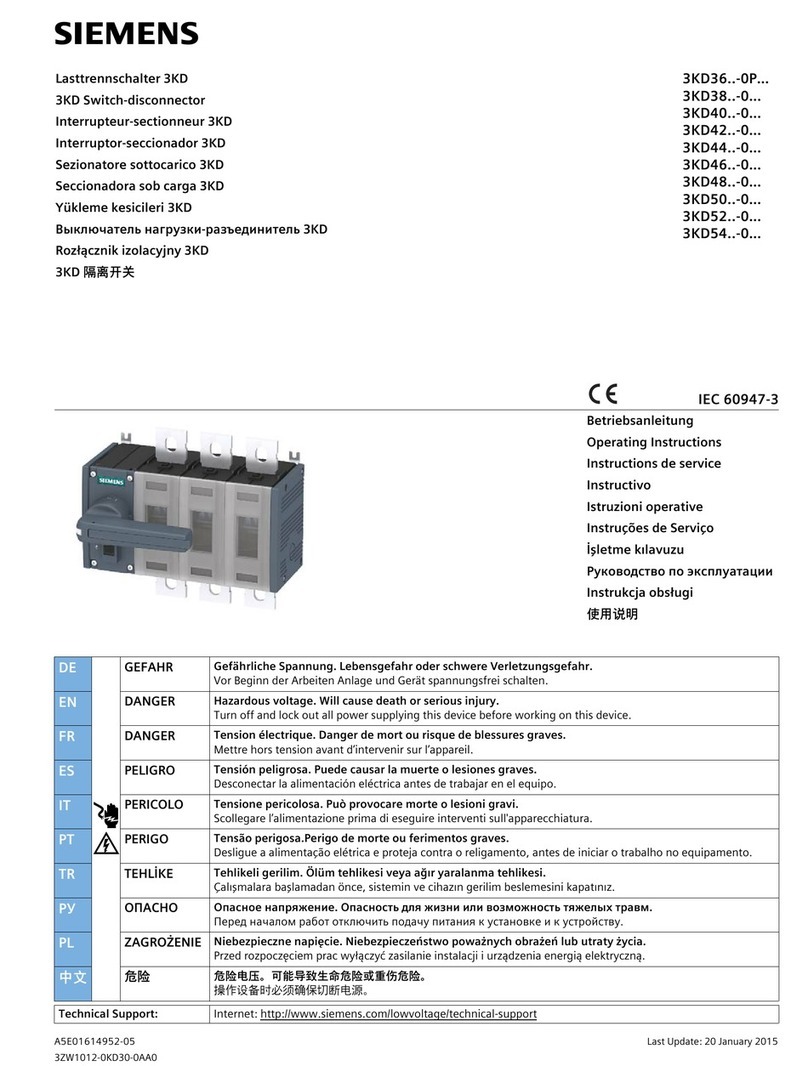
Siemens SCALANCE MM900 Administrator guide

Siemens

Siemens SCALANCE MM900 Administrator guide

Siemens 5-FSV-350 Owner's manual

Siemens

Siemens 5-FSV-350 Owner's manual

Siemens 3NJ630 Series User manual

Siemens

Siemens 3NJ630 Series User manual

Siemens 3LD9340-6 Series User manual

Siemens

Siemens 3LD9340-6 Series User manual

Siemens 3WN6 User manual

Siemens

Siemens 3WN6 User manual

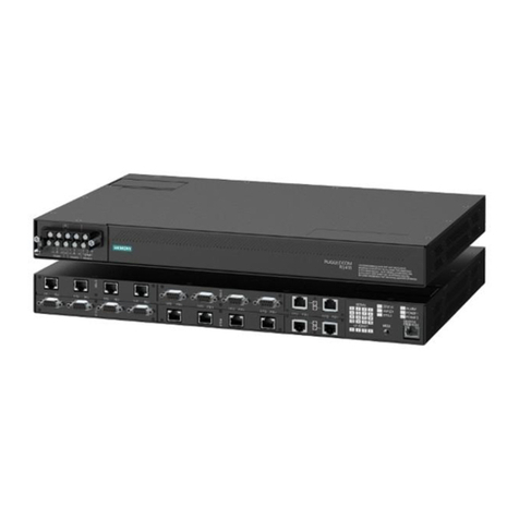
Siemens SIMATIC NET RUGGEDCOM RSG2100 User manual

Siemens

Siemens SIMATIC NET RUGGEDCOM RSG2100 User manual

Siemens SIMATIC HMI User manual

Siemens

Siemens SIMATIC HMI User manual

Siemens SCALANCE XR-300M Administrator guide

Siemens

Siemens SCALANCE XR-300M Administrator guide

Siemens 3VA9977-0KB00 User manual

Siemens

Siemens 3VA9977-0KB00 User manual

Siemens RUGGEDCOM RS950G User manual

Siemens

Siemens RUGGEDCOM RS950G User manual

Siemens RUGGEDCOM RSG920P User manual

Siemens

Siemens RUGGEDCOM RSG920P User manual

Siemens FDMH297-R User manual

Siemens

Siemens FDMH297-R User manual

Siemens SCALANCE XM-400 Instruction sheet

Siemens

Siemens SCALANCE XM-400 Instruction sheet

Siemens SIMATIC NET User manual

Siemens

Siemens SIMATIC NET User manual

Siemens RUGGEDCOM i803 User manual

Siemens

Siemens RUGGEDCOM i803 User manual

Siemens SIMATIC NET RUGGEDCOM RSG2300 User manual

Siemens

Siemens SIMATIC NET RUGGEDCOM RSG2300 User manual

Siemens CNFS Series User manual

Siemens

Siemens CNFS Series User manual

Siemens SCALANCE X-300 Administrator guide

Siemens

Siemens SCALANCE X-300 Administrator guide

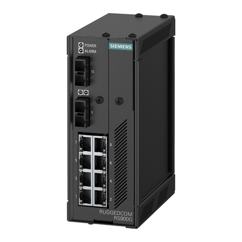
Siemens SIMATIC NET SCALANCE XB-200 Series User manual

Siemens

Siemens SIMATIC NET SCALANCE XB-200 Series User manual

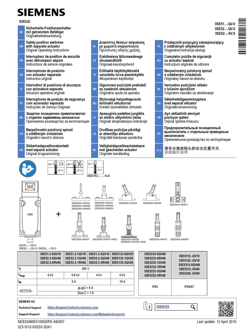
Siemens SIRIUS 3SE53 2-0SH 1 Series User manual

Siemens

Siemens SIRIUS 3SE53 2-0SH 1 Series User manual

Siemens Neutral Kit User manual

Siemens

Siemens Neutral Kit User manual

Siemens QR Series Guide

Siemens

Siemens QR Series Guide

Siemens SCALANCE X-300EEC Administrator guide

Siemens

Siemens SCALANCE X-300EEC Administrator guide

Siemens Pointek CLS200 User manual

Siemens

Siemens Pointek CLS200 User manual

Popular Switch manuals by other brands

Zamel WZM-01/SOS instruction manual

Zamel

Zamel WZM-01/SOS instruction manual

Moxa Technologies EtherDevice EDS-405A-PN installation guide

Moxa Technologies

Moxa Technologies EtherDevice EDS-405A-PN installation guide

Chicken Switch PB16-30C manual

Chicken Switch

Chicken Switch PB16-30C manual

Cisco Catalyst 4500 Series Message guide

Cisco

Cisco Catalyst 4500 Series Message guide

Cisco Nexus 9336C-FX2-E Hardware installation guide

Cisco

Cisco Nexus 9336C-FX2-E Hardware installation guide

FS S3400-48T6SP quick start guide

FS

FS S3400-48T6SP quick start guide

Kohler Decision-Maker MPAC 750 Operation

Kohler

Kohler Decision-Maker MPAC 750 Operation

Cisco CSS 11506 Product bulletin

Cisco

Cisco CSS 11506 Product bulletin

Malmbergs EFE700PIR instruction manual

Malmbergs

Malmbergs EFE700PIR instruction manual

Gefen EXT-DVI-EDIDP user manual

Gefen

Gefen EXT-DVI-EDIDP user manual

Kessel Aqatronic S 85 025 Installation, operation and maintenance instructions

Kessel

Kessel Aqatronic S 85 025 Installation, operation and maintenance instructions

Comtrol RocketPort Serial Hub Si Hardware documentation

Comtrol

Comtrol RocketPort Serial Hub Si Hardware documentation

Atlantis Land A02-F24-4G user manual

Atlantis Land

Atlantis Land A02-F24-4G user manual

Vivotek AW-FGT-100C-120 Quick installation guide

Vivotek

Vivotek AW-FGT-100C-120 Quick installation guide

LEGRAND adorne ASWRRR installation instructions

LEGRAND

LEGRAND adorne ASWRRR installation instructions

Aikexin 4KDK404 user manual

Aikexin

Aikexin 4KDK404 user manual

NETGEAR M7100 Series installation guide

NETGEAR

NETGEAR M7100 Series installation guide

Allied Telesis x950 Series installation guide

Allied Telesis

Allied Telesis x950 Series installation guide

manuals.online logo
manuals.online logoBrands
  • About & Mission
  • Contact us
  • Privacy Policy
  • Terms and Conditions

Copyright 2025 Manuals.Online. All Rights Reserved.