manuals.online logo
Brands
  1. Home
  2. •
  3. Brands
  4. •
  5. Siemens
  6. •
  7. Temperature Controllers
  8. •
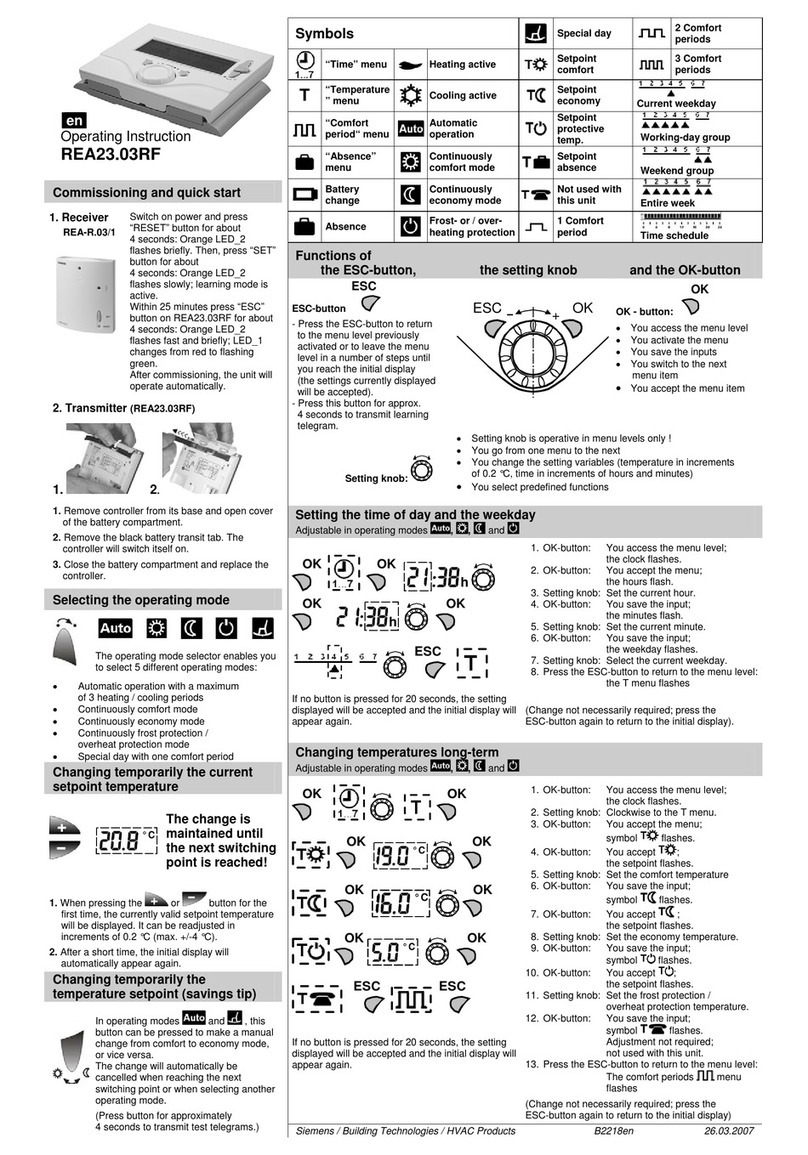
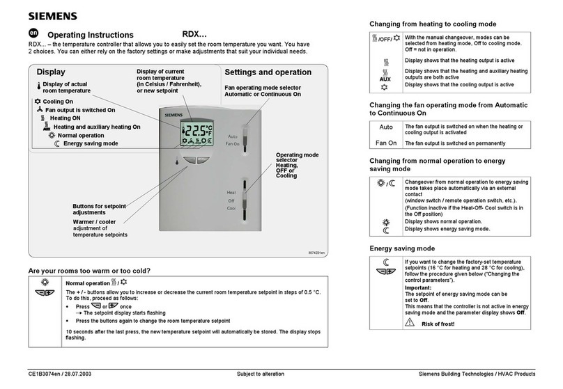
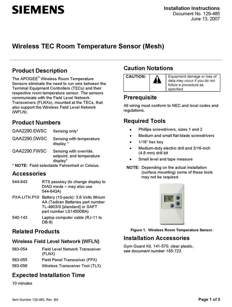
  9. Siemens QAA24 User manual

Siemens QAA24 User manual

CM1N1721E
12.07.2003
Siemens Building Technologies
HVAC Products
1721
QAA24 QAA25…QAA27
Room Temperature
Sensors QAA24...27
with and without setpoint adjuster
Use
In heating, ventilating and air conditioning plants, especially where a high level of com-
fort is required.
Major field of application:
Acquisition and adjustment of room temperature.
Type summary
Type reference Description
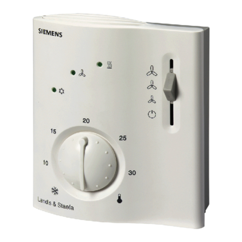
QAA24 Room temperature sensor
QAA25 Room temperature sensor with setpoint adjuster
(setting range 5...35 °C)
QAA26 Room temperature sensor with setpoint adjuster
(setting range 5...30 °C)
QAA27 Room temperature sensor with setpoint adjuster
(setting range ±3 K)
Ordering
When ordering, please give name and type reference, for example:
Room temperature sensor QAA24
.
.
.
.
.
.
.
.
.
.
.
.
.
1721P010
1721P020
2/4
Siemens Building Technologies Room temperature sensors QAA24, QAA25, QAA26, QAA27 CM1N1721E
HVAC Products 12.07.2003
Equipment combinations
Type reference For use with systems/units
QAA24 All systems/units that are capable of acquiring and
handling LG-Ni 1000 signals, such as:
UNIGYR®/VISONIK®, via a measured value module (measu-
red value input for temperature sensors LG-Ni 1000);
Synco™200, Synco™700; AEROGYR™ RWI65...;
TEC™ RCE9...; POLYGYR®RCM6..., RCE6..., RWF...,
RWX... and RWC...; CLASSIC; DESIGO30
QAA25 Synco™200, Synco™700; POLYGYR®RCM6..., RCE6...,
RWF..., RWX... and RWC...
QAA26 UNIGYR®/VISONIK®, via a measured value module (measu-
red value input for temperature sensors LG-Ni 1000);
AEROGYR™ RWI65...; TEC™ RCE9...
QAA27 Synco™200, Synco™700; CLASSIC RKN…;
DESIGO30 RCK...IB and RCH...IB; AEROGYR™ RWI65...
Mechanical design
The units have been designed for wall mounting. They are suitable for use with most
commercially available recessed conduit boxes. The cables can be introduced from the
rear (concealed wiring) or from below or above (surface-run wires) through knock-out
openings.
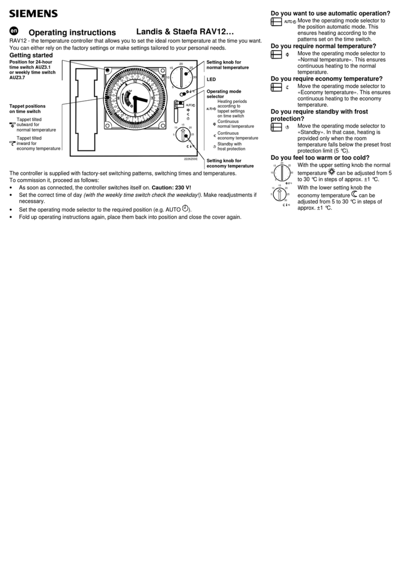
The units consist of two major sections: Casing and baseplate. Both snap together but
can be detached again. The casing accommodates the temperature sensing element
and, depending on the type of unit, various setting and operating elements. The ba-
seplate carries the connecting terminals.
(only with QAA25, QAA26 and QAA27)
Front Rear
123
1721Z01
°C
1 Setting knob for infinite setpoint adjustment
2 Pin for mechanical maximum limitation of setpoint setting range
3 Pin for mechanical minimum limitation of setpoint setting range
For the permissible lengths of lines and measured value errors, refer to «Basic
System Data» of the respective control system.
Engineering notes
For the permissible lengths of lines and measured value errors, refer to «Basic
System Data» of the respective control system.
•UNIGYR®/VISONIK®
When using the QAA26, both the temperature sensor and the setpoint setting unit
must be connected to a measured value input (B...) of the measured value module
(PTM1.2R1K).
.
.
.
.
.
.
.
.
.
Setting and operating
elements
Legend
Disposal
3/4
Siemens Building Technologies Room temperature sensors QAA24, QAA25, QAA26, QAA27 CM1N1721E
HVAC Products 12.07.2003
•AEROGYR™ RWI65...
When using the QAA26 in connection with the RWI65…, the latter must be set to
the setpoint setting range "Heating". In that case, the setpoint of "Heating" on the
RWI65... must be set to 20 °C and additionally, the following must be set:
–Data point 44 to –15 K and data point 45 to + 15 K for RWI65.01
or
–Commissioning data point 9 to –15 K and commissioning data point 10 to +15 K
for RWI65.02
•When using the QAA27, the setpoint adjustment knob must be set to its centre posi-
tion. Additionally, the following must be set:
–Data point 44 to –4 °C and data point 45 to +5 °C for RWI65.01. The offset at data
point 50 must be corrected until data point 2 has value 0.
–Commissioning data point 9 to –15 °C and commissioning data point 10 to +15 °C
for RWI65.02. The offset at commissioning data point 15 must be corrected until
normal data point 2 has value 0.
•POLYGYR®RCM6..., RCE6... and RWF...
For averaging with two temperature sensors and a POLYGYR® controller, the sen-
sors need to be connected in series and the controller requires a setting range insert
AZW61.119-tx50.
If the QAA25 is used with a shift controller, the sensor's range (0...50 °C) is required
for calculating the authority
•CLASSIC RKN…
Setpoint adjustments via QAA27 is possible only with controllers RKN8-L, RKN88-L,
RKN-W and RKN88T.
Fitting and installation notes
Location: On an inner wall of the space to be heated or air conditioned. Not in reces-
ses, shelves, not behind curtains, not opposite or near heat sources.
The unit must not be exposed to direct solar radiation.
The end of the conduit at the sensor must be sealed to prevent false measurements
due to draughts through the conduit.
The permissible ambient conditions should be observed.
Installation instructions are printed on the packing.
Technical data
Range of use 0...50 °C
Setting range refer to «Type summary»
Max. permissible line lengths
and measured value errors refer to «Engineering notes»
Connection terminals for
cross-sectional areas of 2 x 1.5 mm2or 1 x 2.5 mm2
Degree of protection IP 30 to EN 60 529
Safety class III to EN 60 730
Operation to IEC 721-3-3
Climatic conditions class 3K5
Temperature 0...50 °C
Humidity < 85 % r. h.
Transport to IEC 721-3-2
Climatic conditions class 2K3
Temperature −25...+ 65 °C
Humidity < 95 % r. h.
Mechanical conditions class 2M2
conformity to EMC directive 89 / 336 / EEC
General data
Connection terminals
Protective data
Environmental conditions
Norms and standards
4/4
Siemens Building Technologies Room temperature sensors QAA24, QAA25, QAA26, QAA27 CM1N1721E
HVAC Products 12.07.2003
Housing front ASA+PC, NCS S 0502-G (white)
Botton section of housing ASA+PC, NCS 2801-Y43R (grey)
Base PC, NCS 2801-Y43R (grey)
Sensor (entirely) silicon-free
with packaging approx. 0,1 kg
Sensing element 1) LG-Ni 1000 (thin-film element)
Time constant 7 min (depending on air movement and thermal
coupling to the wall)
1) QAA25...27 from serie B on with thin-film element
QAA25 QAA26 QAA27
Setpoint setting range 5...35 °C 5...30 °C ±3 K
Resistance range 95...685 Ω1000...1195 Ω1000...1175 Ω
Resistance value at setpoint 0 K 1091 Ω
10 °C 193,9 Ω1039 Ω
20 °C 390,0 Ω1118 Ω
25 °C 488,3 Ω1157 Ω
30 °C 586,7 Ω1195 Ω
Internal diagram
BM
LG-Ni 1000
1721G01
1721G02
LG-
Ni 1000
RBM
LG-Ni 1000
BMRM
1721G03
B1 Room temperature measuring signal
M Measuring neutral
R Setpoint signal
Dimensions
90
100
°C
32
36
4,2
9,5
56
60
56
60
1721M01
Dimensions in mm
Materials and colors .
.
.
.
Weight
Sensor
Setpoint setting knob
QAA24
QAA25, QAA26
QAA27
Legend
ã2001 Siemens Building Technologies AG n

This manual suits for next models

3

Other Siemens Temperature Controllers manuals

Siemens UP 237K User manual

Siemens

Siemens UP 237K User manual

Siemens 24RFDC/SET User manual

Siemens

Siemens 24RFDC/SET User manual

Siemens REV23.03RF User manual

Siemens

Siemens REV23.03RF User manual

Siemens RCC10U Owner's manual

Siemens

Siemens RCC10U Owner's manual

Siemens 5TC9774-4 Series User manual

Siemens

Siemens 5TC9774-4 Series User manual
Siemens RDF30U Owner's manual

Siemens

Siemens RDF30U Owner's manual

Siemens RDH10RF/SET User manual

Siemens

Siemens RDH10RF/SET User manual

Siemens REV23RF16A User manual

Siemens

Siemens REV23RF16A User manual

Siemens 2200 Series User manual

Siemens

Siemens 2200 Series User manual

Siemens Landis & Staefa REV11 Series User manual

Siemens

Siemens Landis & Staefa REV11 Series User manual

Siemens RDH10RF/SET User manual

Siemens

Siemens RDH10RF/SET User manual

Siemens SIMATIC S5 User manual

Siemens

Siemens SIMATIC S5 User manual

Siemens RDE series User manual

Siemens

Siemens RDE series User manual

Siemens RDF20U User manual

Siemens

Siemens RDF20U User manual

Siemens 1000 Series User manual

Siemens

Siemens 1000 Series User manual

Siemens RAV12 series User manual

Siemens

Siemens RAV12 series User manual

Siemens SITRANS TSinse rt Administrator guide

Siemens

Siemens SITRANS TSinse rt Administrator guide

Siemens 5TC9774-5 Series User manual

Siemens

Siemens 5TC9774-5 Series User manual

Siemens SITRANS TS100 Administrator guide
Siemens

Siemens SITRANS TS100 Administrator guide

Siemens RDD310 User manual

Siemens

Siemens RDD310 User manual

Siemens RDU50U Owner's manual

Siemens

Siemens RDU50U Owner's manual

Siemens REV24RF Installation instructions

Siemens

Siemens REV24RF Installation instructions

Siemens QAA73.110 User manual

Siemens

Siemens QAA73.110 User manual

Siemens SITRANS TSinse rt Administrator guide

Siemens

Siemens SITRANS TSinse rt Administrator guide

Popular Temperature Controllers manuals by other brands

Liebert Liebert iCOM user manual

Liebert

Liebert Liebert iCOM user manual

Linkam Scientific Instruments CI 94 user guide

Linkam Scientific Instruments

Linkam Scientific Instruments CI 94 user guide

V-TAC VT-5145 Installation instruction

V-TAC

V-TAC VT-5145 Installation instruction

Uponor C-33 quick guide

Uponor

Uponor C-33 quick guide

AKO AKO-D14412 installation instructions

AKO

AKO AKO-D14412 installation instructions

Mi WSDCGQ01LM user manual

Mi

Mi WSDCGQ01LM user manual

MULTISPAN TC-49 quick start guide

MULTISPAN

MULTISPAN TC-49 quick start guide

Saunier Duval exacontrol 7 manual

Saunier Duval

Saunier Duval exacontrol 7 manual

alre FETR 101.715 Mounting and installation

alre

alre FETR 101.715 Mounting and installation

Vexve AUTOMIX 10 Mounting and operating instructions

Vexve

Vexve AUTOMIX 10 Mounting and operating instructions

Mitsubishi Electric PAC-USWHS003-TH-1 Installation instructions manual

Mitsubishi Electric

Mitsubishi Electric PAC-USWHS003-TH-1 Installation instructions manual

Micatrone MDT-2000 OPERATING AND INSTALLATION Manual

Micatrone

Micatrone MDT-2000 OPERATING AND INSTALLATION Manual

Middleby Marshall 75729 instructions

Middleby Marshall

Middleby Marshall 75729 instructions

Dantherm SIMPLIFY Quick installation guide

Dantherm

Dantherm SIMPLIFY Quick installation guide

Trane TCONT401AN21MA Comfort Control owner's manual

Trane

Trane TCONT401AN21MA Comfort Control owner's manual

MULTISPAN TC-49P quick start guide

MULTISPAN

MULTISPAN TC-49P quick start guide

STORK TRONIC ST129-JA1TA.10 manual

STORK TRONIC

STORK TRONIC ST129-JA1TA.10 manual

Vortice ACQUA BREEZE SYSTEM Instruction booklet

Vortice

Vortice ACQUA BREEZE SYSTEM Instruction booklet

manuals.online logo
manuals.online logoBrands
  • About & Mission
  • Contact us
  • Privacy Policy
  • Terms and Conditions

Copyright 2025 Manuals.Online. All Rights Reserved.