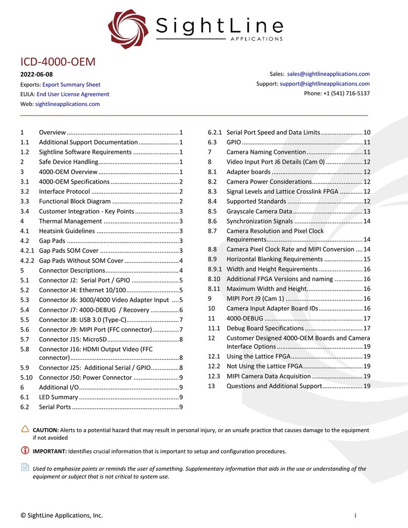
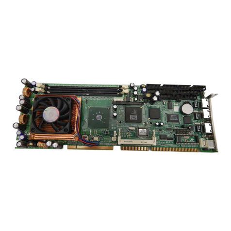
SightLine ICD-1750-OEM User manual

©SightLine Applications, LLC
ICD-1750-OEM
2023-08-22
Exports: Export Summary Sheet
EULA: End User License Agreement
Web: sightlineapplications.com
1Overview ................................................................1
1.1 Additional Support Documentation.......................1
1.2 Sightline Software Requirements ..........................1
2Safe Device Handling..............................................1
31750-OEM Overview ..............................................1
3.1 1750-OEM Specifications .......................................2
3.2 Interface Protocol ..................................................2
3.3 Functional Block Diagram ......................................2
3.4 Comms Block Diagram ...........................................3
3.5 Customer Integration - Key Points .........................3
4Thermal Management ...........................................3
4.1 Heatsink Guidelines ...............................................3
4.2 Gap Pads ................................................................4
5Connector Descriptions..........................................4
5.1 Connector J1: Power, Comms, Ethernet ...............5
5.2 Connector J4: LVDS ................................................5
5.3 Connector J5: USB 3.0............................................6
5.4 Connector J6: 3000/1750 Video Adapter Input .....6
5.5 Connector J8: MIPI Port (FFC Connector) ..............7
5.6 Connector J9: Debug Serial Port............................8
5.7 Connector J10: HDMI Output Video (FFC
Connector) .............................................................8
5.8 Connector J11: Real Time Clock Power In..............8
5.9 Connector J13: MicroSD.........................................9
5.10 Connectors P1 and P2: i.MX8M Plus SOM
Connectors.............................................................9
6Additional I/O.........................................................9
6.1 LED Summary.........................................................9
6.2 Serial and I2C Ports ................................................9
6.2.1 Serial Ports Software Cross Reference.................10
6.2.2 Serial Port and I2C Speed and Data Limits...........10
7i.MX 8M Plus Applications Processor MIPI
Interface...............................................................11
8GPIO .....................................................................11
8.1 Advanced GPIO ....................................................12
9Camera Naming Convention................................12
10 Video Input Port J6 Details (Cam 0) .....................13
11 MIPI Port J8 (Cam 1) ............................................13
12 Questions and Additional Support.......................13
CAUTION: Alerts to a potential hazard that may result in personal injury, or an unsafe practice that causes damage to the equipment
if not avoided.
IMPORTANT: Identifies crucial information that is important to setup and configuration procedures.
Used to emphasize points or remind the user of something. Supplementary information aids in the use or understanding of the
equipment or subject, which is not critical to system use.

ICD-1750-OEM
Revision History
Date
Description
2023-08-15
Updated Serial Port Summary table to show hardware and serial port name relationship.
2023-08-08
Corrected MIPI board and port reference in Serial Port Summary table.
2023-07-25
Updated Serial Port and I2C Speed and Data Limits section.
2023-07-18
Added 1750-OEM communications block diagram.
2023-07-17
Updated 1750-OEM to Rev C1.
2023-06-22
Replaced GPIO tables with new color and letter designator scheme tables.
2023-06-01
Corrected part numbers for J9 Debug Serial port connector and mating connector.
2023-05-28
Updated Serial Ports Software Cross Reference table with Linux locations.
2023-04-28
Preliminary draft created.

ICD-1750-OEM
© SightLine Applications, LLC 1
1Overview
Describes power requirements, thermal management, interface specifications, and connector pinouts
for the 1750-OEM video processing board.
CAUTION: Any customer modifications to SightLine OEM and adapter boards will void the warranty and can
potentially damage the board. Before attempting any modifications, please contact SightLine Support.
1.1 Additional Support Documentation
Panel Plus User Guide provides a complete overview of settings and dialog windows. Accessed from
the Help menu of the Panel Plus application.
Interface Command and Control (IDD) describes the native communications protocol used by the
SightLine Applications product line. Also available as a PDF from the Software Downloads page.
Additional Engineering Application Notes (EANs) and ICDs are available on the Documentation page.
1.2 Sightline Software Requirements
Panel Plus software and firmware versions:
1750-OEM requires Panel Plus and Firmware 3.6.x and higher.
See the camera configuration tables for specific OEM Sightline software version requirements for
supported cameras.
IMPORTANT: Starting with 3.6.x software and above, only the 4000 and 1700 platforms will be
supported. The 1500 and 3000 platforms will continue to be supported in 3.5.x software. Some
features in 3.6.x and above may not be available on 1500 and 3000 platforms.
IMPORTANT: The Panel Plus software version should match the firmware version running on the
OEM. Firmware and Panel Plus software versions are available on the Software Download page.
2Safe Device Handling
CAUTION: To prevent damage to hardware boards, disconnect all input power to OEMs and adapter boards before
connecting or disconnecting cables including all FFC, FPC, KEL, HDMI, MIPI, and round wire (Molex) cables.
CAUTION: To prevent damage to hardware boards, use a conductive wrist strap attached to a good earth ground.
Before picking up an ESD sensitive electronic component, discharge built up static by touching a grounded bare
metal surface or approved antistatic mat.
31750-OEM Overview
The 1750-OEM has 10 connectors and one microSD card slot. Connectors are used to connect power,
Ethernet, Serial ports, MIPI input, HDMI output, USB3, and digital video in (with the use of a 3000-
adapter board).

ICD-1750-OEM
© SightLine Applications, LLC 2
3.1 1750-OEM Specifications
Revision:
C1
Figure 1: 1750-OEM
Dimensions:
45.0 mm (1.77 inch) x 33.3 mm (1.31 inch)
Weight:
16.93 grams
Voltage (VIN):
8V to 15V DC (12V nominal)1
Power:
3W with 12V nominal DC input
Drawing:
1750-OEM
STEP File:
1750-OEM STEP
Rev History:
C: Swapped PCB locations of RTC (J11) and
debug ports (J9). Increase PCB trace clearances
around mounting holes. Added series resistor to
serial ports to reduce crosstalk. Increased
current capacity of Ref Q1 (in-rush limiter).
B2: Initial production release.
All 1750-OEM board mounting holes support M2 screws (0.086 dia.).
3.2 Interface Protocol
The 1750-OEM shares the same interface protocol as other SightLine video processing boards. The
protocol is a packet-based command and control interface. The protocol document is available from the
SightLine website.
3.3 Functional Block Diagram
Figure 2: 1750-OEM Hardware Block Diagram
1
A slightly extended input voltage range is possible with some tradeoffs. Contact Support for more information if this is relevant to your
application.
IO Expander
Magnetics
Crosslink FPGA
UCM-iMX8M Plus SOM
Level Translation
Power Conditioning
J9: Debug Serial
J10: HDMI
J4: LVDS
J5: USB3.0
J8: MIPI CSI
J6: Video to 1080
1750-OEM
LPDDR4
1080p60
H.265
eMMC
10/100 Ethernet
J1: Power, Serial,
J13: uSD Card
J11: RTC Battery

ICD-1750-OEM
© SightLine Applications, LLC 3
3.4 Comms Block Diagram
Figure 3: 1750-OEM Comms Block Diagram
3.5 Customer Integration - Key Points
✓Provide a sufficient heat sink for the i.MX 8M processor and other major components. Close
attention to heatsinking is critical. See the Thermal Management section for more information.
✓Expose Ethernet port (on J1) to an accessible connector for debug, command and control, and
firmware update capability.
✓For in-system recovery, it is recommended to expose the USB programming/debugging port to a
system accessible connector.
✓If you are designing a custom system interface board with the 1750-SOM contact SightLine
Hardware Engineering prior to design for assistance.
4Thermal Management
4.1 Heatsink Guidelines
IMPORTANT: Close attention to heatsinking is critical.
SightLine screens and certifies all 1750-OEM units through the component temperature range of -40°
to 85°C.
All hardware requires some form of mechanical heatsink.
1750-OEM
J1 User IO
Crosslink FPGA
J9 Debug Serial
J6 3000 Adapter
Boards
J4 LVDS Video
Output
MIPI-IN Board
IO Max Expander
Max burst length
128 bytes
J8 MIPI Port
IO SC Expander
Max burst length
64 bytes
UART1 (Serial 0) High BW (SLA Protocol)
UART3 (Serial 3) High BW
UART2 (Serial 1)
I2C5 (dev/i2c4)
200 kHz)
Customer Design
I2C Out Buffer+
4.7K PU
UART0B Low BW
(Serial 8 - LVDS )
UART2B Low BW
(Serial 2 - Cam 0)
I2C6 (dev/i2c5)
400 kHz
Serial 4 - Low BW
Serial 6 - Cam 1 - Low BW
Serial 7 - Low BW
Customer Design
I2C Out
Buffer + 10K PU
(weak)

ICD-1750-OEM
© SightLine Applications, LLC 4
Customers must design a heatsink in conjunction with their system integration effort. It should provide
a direct conducted path to a significant thermal mass (the wall of a gimbal or housing) or use an active
cooling (fans) that has proven to be successful in cases where a full thermal analysis is not performed.
The 1750-OEM typical power consumption is less than 3 W @ 12V. System settings provide an option
for a low power mode with no video output, see EAN-Performance-and-Latency for more information.
IMPORTANT: The internal temperature, reported in Panel Plus, should not exceed +85°C (185°F) or
the SOM processor will start to reduce clock speed and eventually shut down. Internal high
temperatures for extended periods can cause permanent damage.
4.2 Gap Pads
Use some form of thermally conductive material for filling gaps between the hot components and the
heat sink. Examples such as the TGlobal TG-A6200 Ultra Soft Thermal Conductive Pad (6W/mK or
higher) are recommended.
The compression of the pad allows for greater mounting tolerances. The compression of the gap pad
also provides additional support for the board and does not require as much force to maintain contact.
5Connector Descriptions
Figure 4: 1750-OEM Connector Descriptions
Table 1: Connector Descriptions
Connector
Description
Mates with:
J1: Power, Comms, Ethernet
Power In, 2xUART ports, Ethernet
14-Pin Molex Plug
J4: LVDS Out
LVDS, 5V Power Out, Serial (at LVDS levels)
KEL 30-Pin Micro-Coax
J5: USB FPC
USB 3.0 over FPC cable
SLA-CAB-USBC-FPC**
J6: Video Input Adapter
Camera Input Adapter connection
80-Pin Hirose
J8: MIPI Port (FFC connector)
MIPI Port, I2C-6 (Digital Video in 1, serial ports,
w/adapter board)
Sightline Cable SLA-CAB-MIPI-02
J9: Serial Debug*
System recovery and debug serial port
3-Pin JST
J10: HDMI OUT
HDMI Output (FFC)
Sightline Cable SLA-CAB-HD10
J11: RTC Power In
Real Time Clock power supply
2-Pin JST
J13: MicroSD
MicroSD card slot
Standard uSD card
P1, P2: SOM
i.MX8M Plus SOM Connectors
i.MX8M Plus SOM
*The debug serial port is exposed on J9 should be reserved for debugging only. Debug serial port is 3.3V TTL.
**SLA-CAB-USBC-FPC is a directional cable and must be connected correctly. End (A) connects to 1750-OEM on (J5). End (C) connects to the SLA-
FPC-USB-C adapter board. See the SLA-FPC-USB-C section in ICD-Adapter-Boards for more information.

ICD-1750-OEM
© SightLine Applications, LLC 5
5.1 Connector J1: Power, Comms, Ethernet
Connector: Molex 14POS, 53047-1410 Mates with: Molex 14POS Housing, 51021-1400
Table 2: J1 - Power, Comms, Ethernet Pinout
Pin
Signal
Description
1
GND
GROUND
2
TX3
3.3V TTL UART TX
3
RX3
3.3V TTL UART RX
4
GND
GROUND
5
TX1
3.3V TTL UART TX
6
RX1
3.3V TTL UART RX
7
GND
GROUND
8
VIN
POWER SUPPLY INPUT TO OEM
9
VIN
POWER SUPPLY INPUT TO OEM
10
GND
GROUND
11
ETH0_N
ETHERNET PAIR 0, NEGATIVE LEG
12
ETH0_P
ETHERNET PAIR 0, POSITIVE LEG
13
ETH1_P
ETHERNET PAIR 1, POSITIVE LEG
14
ETH1_N
ETHERNET PAIR 1, NEGATIVE LEG
Ethernet supports full duplex.
Supports 10/100BASE-T only.
The 1750-OEM is configured with onboard Ethernet magnetics.
5.2 Connector J4: LVDS
Connector: KEL 30pos, USL00-30L-A Mates with: KEL 30-pos micro-coax
Table 3: J4 - LVDS Pinout
Pin
Signal
Description
1
LVDS0_D3_P
LVDS DATA
2
LVDS0_D3_N
LVDS DATA
3
LVDS0_CLK_P
LVDS CLOCK
4
LVDS0_CLKN
LVDS CLOCK
5
LVDS0_D2_P
LVDS DATA
6
LVDS0_D2_N
LVDS DATA
7
LVDS0_D1_P
LVDS DATA
8
LVDS0_D1_N
LVDS DATA
9
LVDS0_D0_P
LVDS DATA
10
LVDS0_D0_N
LVDS DATA
11
GROUND
GROUND
12
GPIO1
GPIO
13
GPIO0
GPIO
14
P5V
5V POWER OUT
15
P5V
5V POWER OUT
16
P5V
5V POWER OUT
17
P5V
5V POWER OUT
18
P5V
5V POWER OUT
19
GROUND
GROUND
20
GROUND
GROUND
21
GROUND
GROUND
22
GROUND
GROUND
23
GROUND
GROUND
24
GROUND
GROUND
25
P5V
5V POWER OUT
26
RX_N
UART RX NEGATIVE LEG AT LVDS LEVEL
27
RX_P
UART RX POSITIVE LEG AT LVDS LEVEL
28
GROUND
GROUND
29
TX_N
UART TX NEGATIVE LEG AT LVDS LEVEL
30
TX_P
UART TX POSITIVE LEG AT LVDS LEVEL

ICD-1750-OEM
© SightLine Applications, LLC 6
5.3 Connector J5: USB 3.0
Connector: Hirose FH52-18S-0.5SH (99) Mates with: SLA-USB-FPC
Table 4: USB 3.0
Pin
Description
1
GND
2
USB1_TX_N
3
GND
4
USB1_TX_P
5
GND
6
USB1_RX_N
7
GND
8
USB1_RX_P
9
GND
10
GND
11
GND
12
USB1_D_P
13
GND
14
USB1_D_N
15
GND
16
GND
17
USB1_VDD
18
USB1_VDD
USB 5V output can source 900mA max. 5V is also used for MIPI interface boards connected on J8,
as well as LVDS cameras on J4.
CAUTION: Do NOT connect an external 5V power source to the USB connector. Damage to the OEM may
occur.
5.4 Connector J6: 3000/1750 Video Adapter Input
Connector: DF12NB(3.0)-80DP-0.5V(51) Mates with: DF12NB(3.0)-80DS-0.5V(51)
Column key for notes column below (data bit locations):
Y = luminance CbCr = Chrominance G = Grayscale bits.
Table 5: 1750-OEM (J6) Pinout
Pin
Description
Notes
Pin
Description
Notes
2
VIN_BCLK
Alternate Pixel Clock
1
VIN_ACLK
Pixel Clock
4
Ground
3
Ground
6
VIN_D22
5
VIN_D23
8
VIN_D20
7
VIN_D21
10
VIN_D18
9
VIN_D19
12
VIN_D16
11
VIN_D17
14
Ground
13
Ground
16
VIN_D14
Y6, G14
15
VIN_D15
Y7, G15
18
VIN_D12
Y4, G12
17
VIN_D13
Y5, G13
20
VIN_D10
Y2, G10
19
VIN_D11
Y3, G11
22
VIN_D8
Y0, G8
21
VIN_D9
Y1, G9
24
Ground
23
Ground
26
VIN_D6
CbCr6, G6
25
VIN_D7
CbCr7, G7
28
VIN_D4
CbCr4, G4
27
VIN_D5
CbCr5, G5
30
VIN_D2
CbCr2, G2
29
VIN_D3
CbCr3, G3

ICD-1750-OEM
© SightLine Applications, LLC 7
(1750-OEM (J6) Pinout continued)
Pin
Description
Notes
Pin
Description
Notes
32
VIN_D0
CbCr0, G0
31
VIN_D1
CbCr1, G1
34
NC
33
Ground
36
NC
35
NC
38
NC
37
NC
40
NC
39
NC
42
Reserved
Leave floating
41
NC
44
Ground
43
Ground
46
NC
45
VIN_HSYNC
Horizontal Sync
48
NC
47
VIN_VSYNC
Vertical Sync
50
NC
49
VIN_FLD
Field
52
NC
51
VIN_DE
Optional
54
Ground
53
Ground
56
Passthrough ground
55
Passthrough VIN
See J1*
58
Passthrough ground
57
Passthrough VIN
See J1*
60
Passthrough ground
59
Passthrough VIN
See J1*
62
Passthrough ground
61
Passthrough VIN
See J1*
64
Ground
63
Ground
66
TX2
3.3V TTL
65
RX2
3.3V TTL
68
I2C5_SDA_3V3
I2C5 SDA (/dev/i2c-4)
67
I2C5_SCL_3V3
I2C5 SCL (/dev/i2c-4)
70
GPIO5_IO1
GPIO1 (3.3V)
69
GPIO4_IO31
GPIO0 (3.3V)
72
GPIO4_IO30
GPIO3 (3.3V)
71
GPIO4_IO22
GPIO2 (3.3V)
74
GPIO4_IO28
GPIO5 (3.3V)
73
GPIO5_IO2
GPIO4 (3.3V)
76
+3.3V (out)
75
+3.3V (out)
78
Ground
77
Ground
80
+1.8V (out)
79
+1.8V (out)
*Passthrough power available. Max voltage = VIN (See VIN Specifications). Max Current = 1.2A spread across four power and ground pins.
5.5 Connector J8: MIPI Port (FFC Connector)
The MIPI port provides an interface directly connecting MIPI cameras to the 1750-OEM. This port
provides camera power and camera configuration through I2C. For details on supported MIPI cameras
and formats see EAN-MIPI-Cameras. The MIPI port can also be used to connect SightLine video input
adapter boards through the 400-MIPI-IN adapter board. For more information see ICD-Adapter-Boards.
Connector: Hirose 28POS, FH41-28S-0.5SH (050) Mates with: Sightline Cable SLA-CAB-MIPI-02
The mating cycle rating for this connector is 20 cycles.
Limit power supplied over FFC cable to 6.75 watts (1.35A @5V).
Table 6: MIPI Port (J8)
Pin
Description
Pin
Description
2
D3+
1
GND
4
GND
3
D3-
6
D2-
5
D2+
8
CLK+
7
GND
10
GND
9
CLK-
12
D1-
11
D1+
14
D0+
13
GND
16
GND
15
D0-
18
GPIO4_IO26_1V8
17
GPIO5_IO0_1V8
20
I2C6_SCL_1V8 (400 kHz) (/dev/i2c-5)
19
GND
22
GND
21
I2C6_SDA_1V8 (400 kHz) (/dev/i2c-5)
24
GPIO4_IO27_1V8
23
GPIO5_IO5_1V8
26
VCC_5V
25
VCC_5V
28
GND
27
VCC_5V

ICD-1750-OEM
© SightLine Applications, LLC 8
5.6 Connector J9: Debug Serial Port
Connector: JST, BM03B-ADHKS-GAN-ETB(LF)(SN) Mates with: SAL-CAB-0314
Table 7: Extra Serial/GPIO
Pin
Signal
Description
1
GND
2
UART2_TXD
3.3V TTL DEBUG UART
3
UART2_RXD
3.3V TTL DEBUG UART
5.7 Connector J10: HDMI Output Video (FFC Connector)
Connector: Amphenol 20POS, 62674-201121ALF Mates with: Sightline Cable SLA-CAB-HD10
Table 8: HDMI
Pin
Description
Pin
Description
2
HDMI_C_5VOUT*
1
HDMI_C_5VOUT*
4
HDMI_DDC_SDA_5V
3
HDMI_C_HPD_5V
6
HDMI_CEC_3V3
5
HDMI_DDC_SCL_5V
8
GND
7
GND
10
HDMI_TXC_p
9
HDMI_TXC_N
12
HDMI_TX0_N
11
GND
14
GND
13
HDMI_TX0_P
16
HDMI_TX1_P
15
HDMI_TX1_N
18
HDMI_TX2_N
17
GND
20
GND
19
HDMI_TX2_P
*Not intended for customer use.
HDMI output:
•Compliant with HDMI v2.0 output.
•See the SLA-HDMI-SDI section in ICD-Adapter-Boards for details on the HDMI to HDSDI converter
compatible with this HDMI output.
•FFC Ribbon cable and HDMI connectors: ChenYang Elec.
The HDMI output format is specified by the resolution and format specified through Panel Plus. The
HDMI output ignores any EDID HDMI format information in the external HDMI sink device. Supported
HDMI formats are defined in SLAVideoDisplay (0xA4) in the IDD.
5.8 Connector J11: Real Time Clock Power In
Connector: JST 2POS, BM02B-ACHLKS-GAN-ETF Mates with: JST 2POS Housing
Table 9: J50 –Power Connector
Pin
Description
Description
1
VIN
1.6 to 3.6V supply
2
GND
Ground
IMPORTANT: R72 must be removed in order to use the RTC function. Not removing R72 will lead to
a short circuit on any battery/supply connected to J10.

ICD-1750-OEM
© SightLine Applications, LLC 9
5.9 Connector J13: MicroSD
Push the microSD into place. To eject it push it again. The socket is rated up to 10,000 mating cycles
and has 3.3 mm card eject length.
Recommended microSD card types and previously tested models are discussed in the EAN-File-
Recording document.
5.10 Connectors P1 and P2: i.MX8M Plus SOM Connectors
See associated SOM documentation for SOM connector pinouts.
6Additional I/O
6.1 LED Summary
Label
Color
Function
D1
Amber
Ethernet PHY Link Indicator
D2
Green
GPIO5_IO20 LED, Indicates power to system and general SOM
functionality.
6.2 Serial and I2C Ports
All serial ports are 3.3V TTL. When using a SightLine adapter board with a 3-pin connector, use the CAB-
03xx for easy break out to either a pig tail, Molex-to-Molex, or DB-9 connector.
Table 10: 1750-OEM Serial Port Summary
Serial Port Name
Hardware Name (if applicable)
Notes
Serial 8
UART0B
Routed to LVDS Port
Serial 0
UART1
General Purpose (Available on J1 Pins 5:6)
Serial 1
UART2
Debug port
Serial 2
UART2B
Routed to Camera Input Mezzanine (CAM0)
Serial 3
UART3
General Purpose (Available on J1 Pins 2:3)
Serial 4
NA
These serial ports are available when attaching an SLA-4000-MIPI
board to the MIPI port on J8. See the SLA-4000-MIPI section in the
ICD-Adapter-Boards. Serial Port 6 is reserved for Cam1.
Serial 6
Serial 7
Table 11: Serial Ports Hardware Reference - 1750-OEM
Serial Ports
UART0B
UART1
UART2
UART2B
UART3
Connector,
Pin
Rx
Tx
level
Rx
Tx
level
Rx
Tx
level
Rx
Tx
Level
Rx
Tx
level
J4,
30/29
J4,
27/26
LVDS
J1, 6
J1, 5
3.3V
J9, 3
J9, 2
3.3V
J6, 65
J6, 66
3.3V
J1, 3
J1, 2
3.3V
Table 12: I2C Ports
Hardware Name
Notes
I2C-5 (/dev/i2c-4)
Routed to on-board J6 FPGA and 3000-Input mezzanine.
I2C-6 (/dev/i2c-5)
Routed to MIPI connector and to IO expander that generates UART serial ports for the 3000-Input
mezzanine boards, as well as the LVDS port.

ICD-1750-OEM
© SightLine Applications, LLC 10
6.2.1 Serial Ports Software Cross Reference
Table 13: Serial Ports Software Cross Reference - 1750-OEM
Connector
Serial Port Name
Linux Location
Use Cases*
Cam ID
J1
Serial 0
/dev/ttymxc0 or
/dev/ttySLA_00
SightLine Video Protocol (SVP) / other protocol
types / user defined / other
J9
Serial 1
/dev/ttymxc1 or
/dev/ttySLA_01
Debug port
J6
Serial 2
/dev/ttySC1 or
/dev/ttySLA_02
Camera control / pass through / protocol types /
other
Cam 0
J1
Serial 3
/dev/ttymxc2 or
/dev/ttySLA_03
User defined / protocol types / other
J8
Serial 4
/dev/ttyMAX04 or
/dev/ttySLA_04
User defined / protocol types / other
J8
Serial 6
/dev/ttyMAX06 or
/dev/ttySLA_06
MIPI
Cam 1
J8
Serial 7
/dev/ttyMAX07 or
/dev/ttySLA_07
User defined / protocol types / other
J4
Serial 8
/dev/ttySC0 or
/dev/ttySLA_08
LVDS
*See Set Port Configuration for common Protocol Types or EAN-Ethernet-and-Serial-Communication.
6.2.2 Serial Port and I2C Speed and Data Limits
Serial ports 2 and 8 are controlled over an I2C bus using an I2C to serial bridge chip, while the other
serial ports are native from the processor. All serial ports can communicate at speeds up to 921.6kbps
but there are limits on the maximum data packet size at this rate (see the Comms Block Diagram).
The I2C bus default speed is 400 kHz. The I2C bus speeds are not currently changeable by the customer.
I2C-5 bus speed is currently at 200Mhz in software version 3.6.x.
Table 14: I2C and Serial Port Speed Summary
Ports
Default Bus Speed
1, 2, 3, 4, 6, 7
115.2kbps
0B, 2B
115.2kbps
I2C-6
400 kHz (cannot be set to 1MHz)
I2C-5
200 kHz (release 3.6)
CAUTION: The I2C bus is shared by a small number of peripherals on the 1750-OEM. Setting I2C to 1MHz can cause
system instability or crashes.
The following camera I/F boards are known to be incompatible with 1MHz clock when placed on the
4000-MIPI adapter connected to J8:
•SLA-3000-HDSDI (Rev C or older, rev C1 is compatible)
•SLA-3000-HDMI
•SLA-3000-AB
•SLA-3000-FPC with Airborne camera
•SLA-3000-FPC with SLA-FPC-LI board
•Some custom I/F boards
CAUTION: Some boards are checked by software and will not switch to 1MHz. Other boards cannot be checked by
software. It is the responsibility of the user to avoid incompatibilities and resulting system crashes.

ICD-1750-OEM
© SightLine Applications, LLC 11
7i.MX 8M Plus Applications Processor MIPI Interface
13.5.1.2 Features:
•Compliant to MIPI CSI2 Specification V1.3 except for C-PHY feature
•YUV420, YUV420 (Legacy), YUV420 (CSPS), YUV422 of 8-bits and 10-bits
•RGB565, RGB666, RGB888
•RAW6, RAW7, RAW8, RAW10, RAW12, RAW14
•Support 1 to 4 lanes of D-PHY
•Interfaces
•Supports both continuous and non-continuous (LP-HS) MIPI clock.
8GPIO
The 1750-OEM has seven accessible GPIOs. Six of these GPIOs are routed to the camera adapter board
port J6. One GPIO can be exposed to the round wire connector J1 by modifying resistor placements on
the PCB.
Four of the six GPIOS that are routed to the adapter board are used by SightLine software to detect the
adapter board ID. On some adapter boards the remaining two GPIOs are exposed to round wire
connectors for customer use. In rare cases the four GPIOs used to detect the board ID may also be
available for customers, though their use is restricted. Contact Support for more information.
All GPIOs on the connectors operate at a voltage of 3.3V, although they can be converted to different
voltage domains on the connected adapter boards.
The ICD-Adapter-Boards has a Camera Input Adapter Board IDs table, which provides a list of camera
input adapter boards and their corresponding IDs. Additionally, the GPIO table in the ICD provides a list
of GPIOs that are accessible through round wire connectors on the different camera adapter boards,
along with their respective voltage levels.
All GPIO pins have both a hardware name (e.g., GPIO4_IO31) and a Linux port name that can be used
for control through the operating system (e.g., gpio127). GPIO pins are referenced by schematic name
and Linux port name, e.g., GPIO4_IO31 (Linux gpio127).
The Linux port names for these GPIOs are listed in Table 15 for adapter boards connected to the 1750-
OEM on J6.
Using the color and letter designator scheme these GPIOs can be cross referenced with the Customer
Accessible GPIOs and Cross Reference table in the GPIO section of the ICD-Adapter-Boards to match the
correct software name to the physical location for GPIOs exposed on SightLine adapter boards.
The voltage level for GPIOs coming off adapter boards is dependent on the adapter board as
specified in the ICD-Adapter-Boards.

ICD-1750-OEM
© SightLine Applications, LLC 12
Table 15: GPIO Software Cross Reference - 1750-OEM
Cross Reference Designator
HW Name (on schematic)
Physical Location (Connector, Pin)
Linux location
(in /sys/class/gpio/)
A
GPIO4_IO31
J6, Pin 69
gpio127
B
GPIO5_IO1
J6, Pin 70
gpio129
C
GPIO4_IO22
J6, Pin 71
gpio118
D
GPIO4_IO30
J6, Pin 72
gpio126
E
GPIO5_IO2
J6, Pin 73
gpio130
F
GPIO4_IO28
J6, Pin 74
gpio124
Not routed to adapter boards
GPIO5_IO19
Contact Support
Contact Support
When the SLA-4000-MIPI board is connected to the system, the GPIOs from J10 and J2 on the MIPI
board will be mapped to the Linux OS as shown in Table 16. These GPIOs are only available when the
MIPI board is connected.
Table 16: GPIO Software Cross Reference for GPIOs - SLA-4000-MIPI
Cross Reference Designator
HW Name (on schematic)
Physical Location (Connector, Pin)
Linux location
(in /sys/class/gpio/)
A
GPIO0_3000_BRD
J10, Pin 69
Gpio
B
GPIO1_3000_BRD
J10, Pin 70
Gpio
C
GPIO2_3000_BRD
J10, Pin 71
Gpio
D
GPIO3_3000_BRD
J10, Pin 72
Gpio
E
GPIO4_3000_BRD
J10, Pin 73
Gpio
F
GPIO5_3000_BRD
J10, Pin 74
Gpio
Not routed to adapter boards
GPIO6_USER
J2, Pin 7
Gpio
Not routed to adapter boards
GPIO13_OPEN_DRAIN
J2, Pin 8
Gpio
8.1 Advanced GPIO
The GPIO information shown in Table 17 is intended to be used as a starting point for customers
designing their own carrier boards and custom applications. They are not intended to be user
accessible.
Other GPIOs not shown in this table or other GPIO software reference tables are not available for
customer use. Please contact SightLine Support for more information.
Table 17: Advanced GPIO Descriptions - 1750-OEM
Connector, Pin
GPIO Port Hardware Name
Description
NA
GPIO9_FPGA
FPGA communication with 1750-SOM
NA
GPIO10_FPGA
FPGA communication with 1750-SOM
NA
LVDS_GPIO0
LVDS communication with 1750-SOM
NA
LVDS_GPIO1
LVDS communication with 1750-SOM
9Camera Naming Convention
Connector:
Appears in software as:
J6 (3000-Adapter board 80 Pin)
Camera 0 (Cam 0)
J8 (MIPI - 28 pin Basler style)
Camera 1 (Cam 1)
J5 USB3 (USB camera)
Camera 2 (Cam 2)

ICD-1750-OEM
© SightLine Applications, LLC 13
10 Video Input Port J6 Details (Cam 0)
When acquiring video, a set of adapter boards are available to convert popular video signals to parallel
digital video for input to the J6 video input port. For specific details see ICD-OEM-Camera-Side-
Interfaces. Parallel video can be acquired using an adapter board that accepts FFC and FPC cable types.
Mating adapter boards are available that attach to specific camera types (Boson, Airborne, etc.). For
more information see the ICD-OEM-Camera-Side-Interfaces for cable instructions and precautions.
See the Video Input Port J6 Details (Cam 0) section in ICD-4000-OEM for camera input details and
supported formats. The 1750-OEM processor will support the same interfaces and formats as the
4000-OEM except BT.656, which is not currently supported on the 1750-OEM.
11 MIPI Port J8 (Cam 1)
The MIPI port provides an interface directly connecting MIPI cameras to the 4000-OEM. This port
provides camera power and camera configuration through I2C. For details on supported MIPI cameras
and formats see EAN-MIPI-Cameras.
The MIPI port can also be used to connect SightLine Video Input adapter boards through the 4000-MIPI
adapter board. For details on the 4000-MIPI and Video Input Boards, see ICD-OEM-Camera Side-
Interfaces.
The MIPI port supported cameras and formats are the same as the 4000-OEM. See the MIPI Port J9
(Cam 1) section in the ICD-4000-OEM for details.
12 Questions and Additional Support
For questions and additional support, please contact SightLine Support. Additional support
documentation and Engineering Application Notes (EANs) can be found on the Documentation page of
the SightLine Applications website.
Other manuals for ICD-1750-OEM
1
This manual suits for next models
1
Table of contents
Other SightLine Computer Hardware manuals

SightLine
SightLine 3000-OEM User guide

SightLine
SightLine 1750-OEM User manual

SightLine
SightLine 1500-OEM User manual

SightLine
SightLine ICD-4000-OEM User manual

SightLine
SightLine 3000-OEM User manual

SightLine
SightLine 1750-OEM User manual

SightLine
SightLine 1500-EVAL Kit User guide

SightLine
SightLine 1750-OEM User manual

SightLine
SightLine 3000-OEM User guide

SightLine
SightLine 1750-OEM User manual