SIHOO M57 User manual

MODEL: M57
USER
MANUAL
WhatsApp
Scan to Contact
www.sihoooffice.com
Sihoo Store US Sihoo Store EU Instagram

service@sihooofffice.com
We hope our products can enhance your comfo and
promote a healthy lifestyle.
We take pride in oering a comprehensive three-year
warranty for all Sihoo products, suppoed by
round-the-clock customer seice to guarantee your
utmost satisfaction.
Should you require any assistance, please do not hesitate to
contact us at
Kindly note: To expedite our seices, kindly include your
order number when reaching out to our customer suppo.
Sincerely,
Thank you for choosing Sihoo. Sihooを選んでいただき、ありがとうございます。
どうぞよろしくお願いいたします。
私たちの製品がお客様の快適さを向上させ、健康的なライフスタ
イルを促進できることを願っています。
Sihooのすべての製品に対して、包括的な3年間の保証を提供し、
常時対応のカスタマーサービスでお客様の最大の満足を保証しており
ます。
ご注意:サービスを迅速に提供するために、カスタマーサポート
にお問い合わせいただく際には、ご注文番号をご記入いただけると助
かります。
お手伝いが必要な場合は、どうぞお気軽に
service@sihoooffice.comまでお問い合わせください。

ABOUT US
Sihoo is a renowned specialist in ergonomic furniture, dedicated to oering healthy and
comfoable ergonomic chairs. With a 12-year emphasis on technology and well-being,
Sihoo's mission is to enhance people's lives through innovative and ergonomic furniture
solutions. Presently, Sihoo's ergonomic chairs are available in over 100 countries and
have garnered acclaim among Foune 500 companies, as well as in more than 10 million
households worldwide.
CAUTION !
Work on gas springs only by
trained specialist personnel.
ACHTUNG !
Arbeiten an Gasfedern nur durch
eingewiesenes Fachpersonal.
Séparez les éléments avant de trier
BARQUETTE
ÉTUI
FILM
CONTENTS
1.User Manual
2.Benutzerhandbuch
3.Manuel utilisateur
5.Manual de usuario
4.Manuale utente
6.組立説明書
7.
P01-P04
P05-P08
P09-P12
P13-P16
P17-P20
P21-P24
P25-P28

Pas List
(Please refer to the actual size. Each type of screw and washer has one reseed as a spare.)
Note: Please so the screws and measure their lengths beforehand for easier assembly.
User Manual
BChair leg tube
5pcs
A
Castor
5pcs
Small Shim
F
10pcs
HGas lift
1pc
I
Seat cushion
1pc
1pc
1pc
EChair leg screw (M6X12)
10pcs
1pc
1pc
D
Hex wrench
1pc
M
Armrest screw/
Mechanism screw(M6*20)
10pcs 1pc
G
Chair foot trim cover
1pc
C
Chair leg tube connection base
1pc
K
Back plate screw(M8*45)
3pcs 1pc
N
O
P
Big Shim
Mechanismus
Kopfstütze
1pc4pcs
LArmrest
1
pair
JBackrest
1
pc
01 02
PaDescriptionKey Qty. Spare
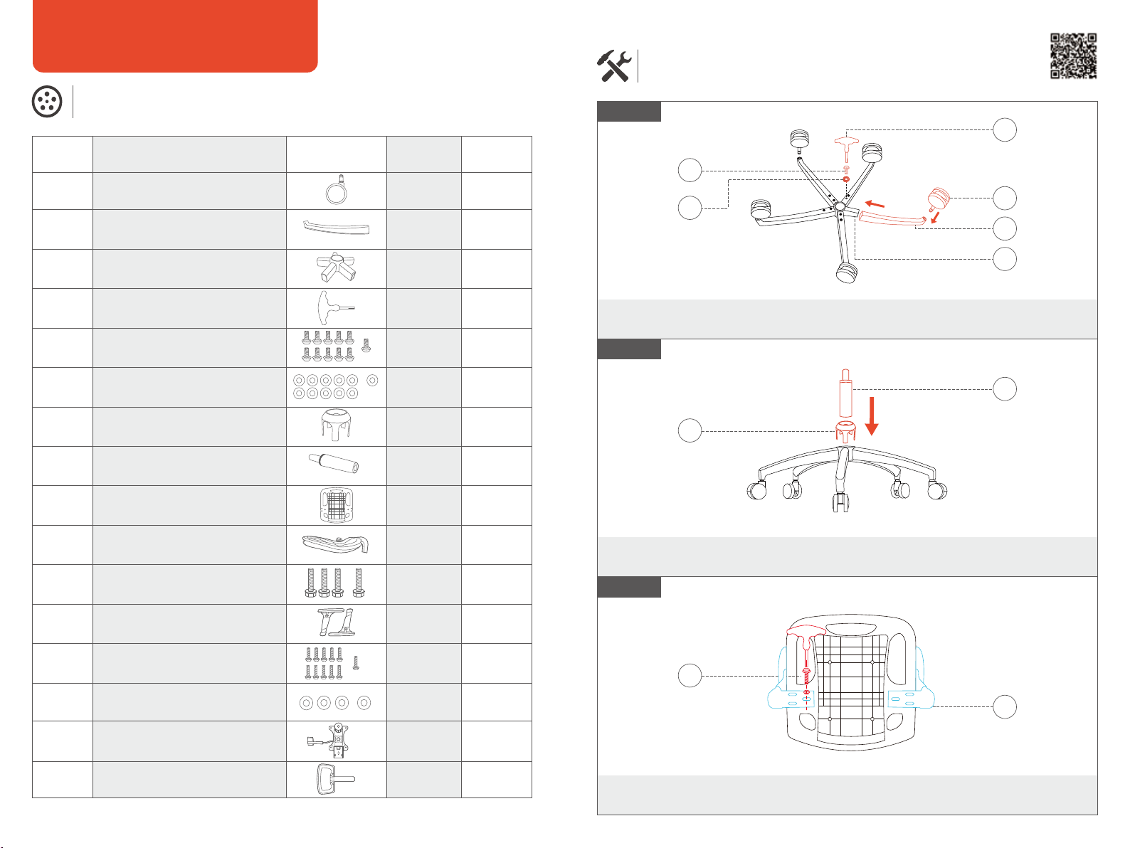
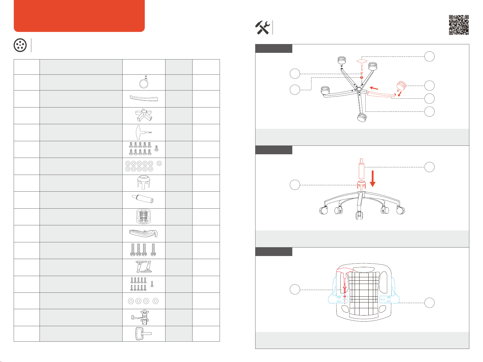
Assembly Instructions
(Please refer to the actual size.)
Use 10 screws of M6*12 specication to x the vechair leg tubes tothe chair leg tube
connection base and then inse the wheels;
First, inse the chair foot trim cover into the chair foot, and then put the air pressure rod
into the middle hole of chair leg tube connection base;
Fix the armrest to the seat cushion with 6pcs small shim and 6pcs (M6*20) screws.
H
G
Step 1
Step 2
Step 3
Scan for
Video Guide
A
D
B
C
E
F
M
L
03 04
Operation Instructions
(Please refer to the actual size.)
Safety Installation
1. Each chair is designed to suppo the weight of one person only.
2. Please use the chair on a at, even suace.
3. Do not allow children under the age of 5 to sit on the chair without supeision.
4. Avoid sitting on the armrest to prevent potential accidents.
5. Do not stand on the chair, use it as a ladder, or step on it.
6. Please refrain from placing excessive weight on the chair or using it as a makeshift trolley.
7. Avoid using sharp or pointed objects that could damage the chair, and keep it away from
open ames or sources of heat.
8. For your safety, do not attempt to disassemble the gas lift mechanism.
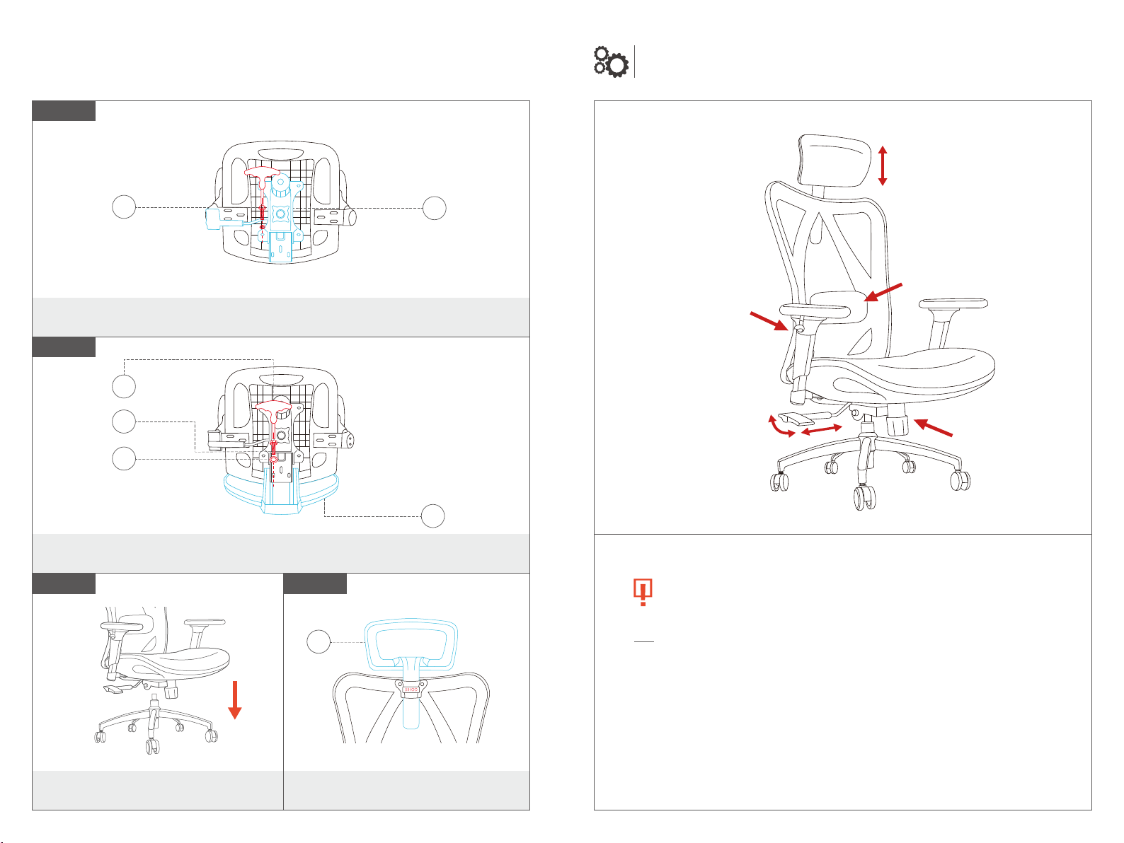
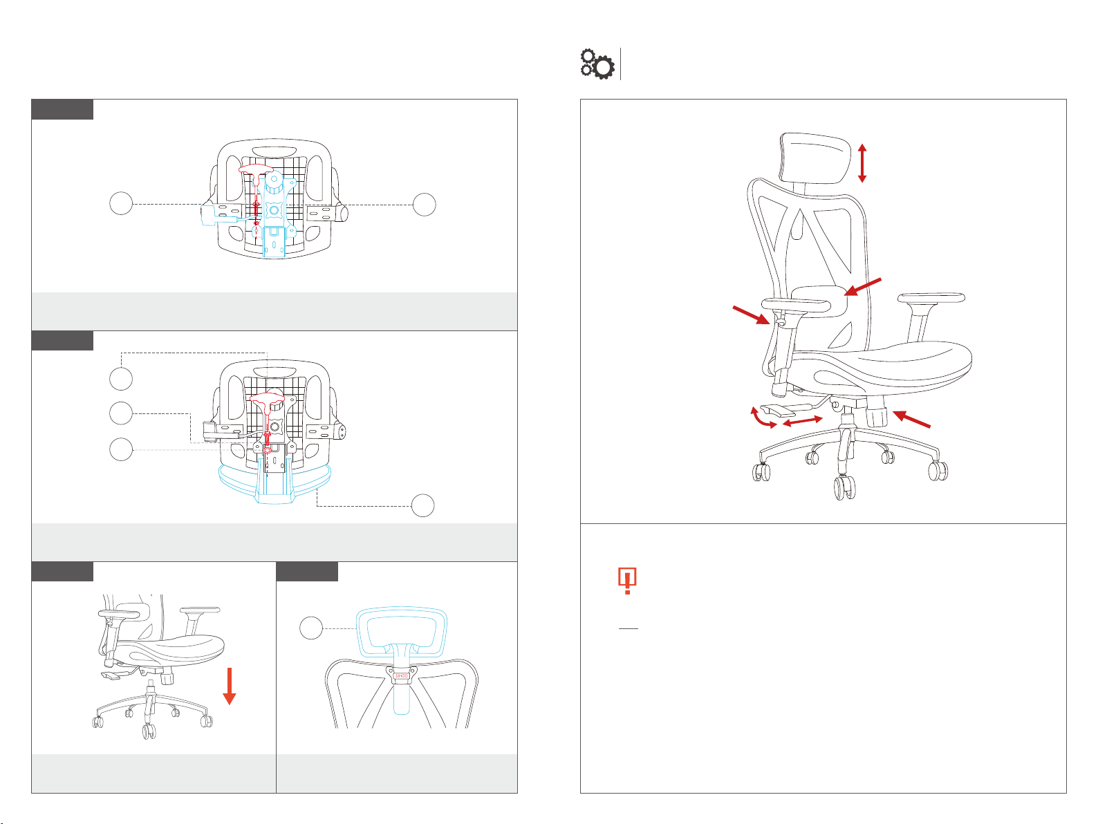
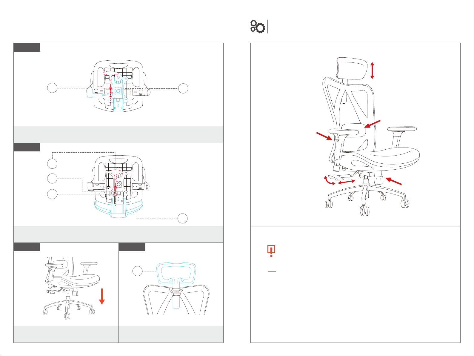
Fix the mechanism to the seat cushion with 4pcs small shim and 4pcs (M6*20) screws.
Fix the back plate to the seat cushion with 3pcs big shim and 3pcs (M8*45) screws.
Put the mechanism into the gaslift.
Step 4
Step 5
Step 6
O
M
N
D
K
J
Headrest height
adjustment
Lumbar suppo depth &
height adjustment
Backrest tilt tension
adjustment
3D armrest(height;
horizontal;forward and
backward adjustment)
Seat height
adjustment
Backrest tilt angle
adjustment
Step 7
Inse the headrest into the slot.
P
Hinweis: Bitte soieren Sie die Schrauben im Voraus und messen Sie ihre Längen, um die Montage zu erleichtern.
Benutzerhandbuch
B
Stuhlbeinrohr 5Stücke
A
Castor 5Stück
Kleine Distanzscheibe
F
10pcs
H
Gaslift 1Stück
I
Sitz
1pc
1pc
1pc
E
Stuhlbeinschraube (M6 * 12)
10pcs
1pc
1pc
D
Inbusschlüssel
1pc
M
Armlehnenschraube/
Mechanismusschraube (M6*20)
10pcs 1pc
G
Stuhlfußverkleidung 1Stück
C
Stuhlbeinroherbindung Basis 1Stück
K
Rückplattenschraube
(M8*45)
3
Stück
1pc
N
O
P
Große Distanzscheibe
Mechanismus
Kopfstütze
1pc4pcs
L
Armlehnen 1Paar
J
Rückenlehne
1
pc
05 06
Verwenden Sie 10 Schrauben der Spezikation M6*12, um die fünf Stuhlbeinrohre an
der Stuhlbeinrohr-Verbindungsbasis zu befestigen,und setzen Sie dann die Räder ein;
Setzen Sie zuerst die Verkleidungsabdeckung des Stuhlfußes in den Stuhlfuß ein und stecken
Sie dann die Luftdruckstange in das mittlere Loch der Verbindungsbasis des Stuhlbeinrohrs;
Befestigen Sie die Armlehne mit 6 kleinen Scheiben und 6 Schrauben (M6*20) am Sitz.
H
G
Schritt 2
Schritt 3
Nach
Videoanleitung suchen
A
D
B
C
E
F
M
L
Stückliste
(Bitte beachten Sie die tatsächliche Größe. Von jeder A Schraube und Unterlegscheibe ist jeweils
eine als Ersatz vorgesehen.)
Montageanleitung
(Bitte beachten Sie die tatsächliche Größe.)
TeilBeschreibungSchlüssel Menge Ersatz
Schritt 1

07 08
Befestigen Sie den Mechanismus mit 4 kleinen Scheiben und 4 Schrauben (M6*20)
am Sitz.
Befestigen Sie die Rückenplatte mit 3 großen Distanzscheiben und 3 Schrauben
(M8*45) am Sitz.
Schritt 4
Schritt 5
Schritt 6
O
M
N
D
K
J
Höhenverstellung der
Kopfstütze
Lordosenstützentiefe und
Höheneinstellung
Einstellung der
Neigungsspannung
der Rückenlehne
3D-Armlehneneinstellung
Sitzhöhenverstellung
Winkelverstellung
der Rückenlehne
Betriebsanleitung
(Bitte beachten Sie die tatsächliche Größe.)
Sicherheitsanweisungen
1. Jeder Stuhl ist nur für das Gewicht einer Person ausgelegt.
2. Bitte verwenden Sie den Stuhl auf einer achen, ebenen Obeläche.
3. Erlauben Sie Kindern unter 5 Jahren nicht, ohne Aufsicht auf dem Stuhl zu sitzen.
4. Vermeiden Sie das Sitzen auf der Armlehne, um mögliche Unfälle zu verhindern.
5. Stehen Sie nicht auf dem Stuhl, verwenden Sie ihn nicht als Leiter oder Tritt.
6. Bitte verzichten Sie darauf, übermäßiges Gewicht auf den Stuhl zu legen oder ihn als
improvisieen Transpowagen zu verwenden.
7. Verwenden Sie keine schaen oder spitzen Gegenstände, die den Stuhl beschädigen könnten,
und halten Sie ihn fern von oenen Flammen oder Hitzequellen.
8. Aus Sicherheitsgründen versuchen Sie nicht, den Gasliftmechanismus zu demontieren.
Schritt 7
Setzen Sie den Mechanismus in den
Gasheber.
Setzen Sie die Kopfstütze in den
Schlitz ein.
P

Note : Veuillez trier les vis et mesurer leurs longueurs au préalable pour faciliter l'assemblage.
Manuel de l'utilisateur
B
Tube de jambe de chaise 5pièces
A
Roulette
5pcs
Petite cale
F
10pcs
H
Élévateur de gaz
1pc
I
Siège
1pc
1pc
1pc
E
Vis de jambe de chaise (M6 * 12)
10pcs
1pc
1pc
D
Clé hexagonale
1pc
M
Vis d'accoudoir/Mécanisme
à vis (M6*20)
10pcs
1pc
G
Couveure de garniture
de pied de chaise
1pièce
C
Base de connexion du tube
de jambe de chaise
1pc
K
Vis de la plaque arrière (M8*45)
3pcs
1pc
N
O
P
Grande cale
Mécanisme
Appuie-tête
1pc
4pcs
L
Accoudoirs
1paire
J
Dossier
1
pc
09 10
Utilisez 10 vis de spécication M6 * 12 pour xer les cinq tubes de pied de chaise à la base
de connexion du tube de pied de chaise, puis insérez les roues ;
Tout d'abord, insérez le couvercle de garniture du pied de chaise dans le pied de chaise,
puis placez la tige de pression d'air dans le trou central de la base de connexion du tube
de pied de chaise ;
Fixez l'accoudoir au siège à l'aide d'une petite cale d'épaisseur et de 6 vis (M6*20).
H
G
Étape 2
Étape 3
A
D
B
C
E
F
M
L
Liste des pièces
(Veuillez vous référer à la taille réelle. Chaque type de vis et de rondelle en a une de réseée en tant
que pièce de rechange.)
Instructions d'assemblage
(Veuillez vous référer à la taille réelle.)
Guide de
numérisation vidéo
PièceDescriptionClé Qté. De rechange
Étape 1
11 12
Fixez le mécanisme au siège à l’aide de 4 petites cales et de 4 vis (M6*20).
Fixez la plaque arrière au siège avec 3 grosses cales et 3 vis (M8*45).
Étape 4
Étape 5
Étape 6 Étape 7
O
M
N
D
K
J
Headrest height
adjustment
Lumbar suppo depth &
height adjustment
Backrest tilt tension
adjustment
3D armrest(height;
horizontal;forward and
backward adjustment)
Seat height
adjustment
Backrest tilt angle
adjustment
Instructions d'utilisation
(Veuillez vous référer à la taille réelle.)
Instructions de sécurité
1. Chaque chaise est conçue pour suppoer le poids d'une seule personne.
2. Veuillez utiliser la chaise sur une suace plane et stable.
3. Ne permettez pas aux enfants de moins de 5 ans de s'asseoir sur la chaise sans sueillance.
4. Évitez de vous asseoir sur l'accoudoir pour prévenir d'éventuels accidents.
5. Ne montez pas sur la chaise, ne l'utilisez pas comme une échelle, ni ne montez dessus.
6. Veuillez vous abstenir de placer un poids excessif sur la chaise ou de l'utiliser comme un
chariot improvisé.
7. Évitez d'utiliser des objets pointus ou coupants qui pourraient endommager la chaise,
et éloignez-la des ammes nues ou de toute source de chaleur.
8. Pour votre sécurité, ne tentez pas de désassembler le mécanisme de levage au gaz.
Placez le mécanisme dans l'ascenseur
à gaz.
Insérez l'appui-tête dans la fente.
P

Lista delle pai
(Si prega di fare riferimento alle dimensioni eettive. C'è una risea per ciascun tipo di vite e
rondella.)
Manuale Utente
B
Tubo della gamba della sedia 5 pezzi
A
Casto
5pcs
Piccolo spessore
F
10
pz
H
Gas lift 1 pz
I
Sede
1pc
1pc
1pc
E
Vite per gambe della
sedia (M6 * 12)
10pcs
1pc
1pc
D
Chiave esagonale
1pc
M
Vite del bracciolo/Vite del
meccanismo (M6*20)
10pcs 1pc
G
Copeura del rivestimento
del piede della sedia
1pc
C
Base di collegamento del tubo
della gamba della sedia 1pezzo
K
Vite del piatto posteriore (M8*45)
3pcs 1pc
N
O
P
Big Shim
Meccanismo
Poggiatesta
1pc4pcs
L
Braccioli 1 paio
J
Schienale
1
pc
13 14
Istruzioni di montaggio
(Si prega di fare riferimento alle dimensioni eettive.)
Utilizzare 10 viti della specica M6*12 per ssare i cinque tubi della gamba della sedia alla
base di collegamento del tubo della gamba della sedia, quindi inserire le ruote;
In primo luogo, inserire la copeura del rivestimento del piedino della sedia nel piedino
della sedia, quindi inserire l'asta della pressione dell'aria nel foro centrale della base di
collegamento del tubo della gamba della sedia;
Fissare il bracciolo al sedile con viti 6pcs piccolo e 6 pezzi (M6*20).
H
G
Paso 1
Paso 2
Paso 3
Scansione
per Guida Video
A
D
B
C
E
F
M
L
Nota: Si prega di ordinare le viti e misurare in anticipo le loro lunghezze per facilitare l'assemblaggio.
PaeDescrizioneChiave Qtà. Di
Ricambio
15 16
Istruzioni per l'Uso
(Si prega di fare riferimento alla dimensione eettiva.)
Fissare il meccanismo al sedile con 4 pezzi di piccole dimensioni e 4 viti (M6*20).
Fissare la piastra posteriore al sedile con 3 pezzi di grosso spessore e 3 viti (M8*45).
Metti il meccanismo nel sollevatore a gas.
Paso 4
Paso 5
Paso 6
O
M
N
D
K
J
Regolazione dell'altezza
del poggiatesta
Profondità suppoo lombare
e regolazione in altezza
Regolazione della
tensione di inclinazione
dello schienale
Regolazione del bracciolo 3D
Regolazione
dell'altezza del sedile
Regolazione dell'inclinazione
dello schienale
Istruzioni per la Sicurezza
1. Ogni sedia è progettata per sostenere il peso di una sola persona.
2. Si prega di utilizzare la sedia su una supeicie piana e livellata.
3. Non permettere a bambini sotto i 5 anni di sedersi sulla sedia senza supeisione.
4. Evita di sedei sul bracciolo per prevenire potenziali incidenti.
5. Non stare in piedi sulla sedia, usarla come scala o calpestarla.
6. Si prega di astenersi dal mettere peso eccessivo sulla sedia o dall'usarla come carrello
improvvisato.
7. Evita di utilizzare oggetti alati o appuntiti che potrebbero danneggiare la sedia e mantienila
lontana da amme apee o fonti di calore.
8. Per la tua sicurezza, non cercare di smontare il meccanismo di sollevamento a gas.
Paso 7
Insee el reposacabezas en la ranura.
P

Lista de piezas
(Por favor, consulte el tamaño real. Cada tipo de tornillo y arandela tiene uno reseado como
repuesto.)
Manual del Usuario
B
Tubo de la pata de la silla 5piezas
A
Rueda 5piezas
Pequeña calza
F
10pcs
H
Elevador de gas
1pc
I
Asiento
1pc
1pc
1pc
E
Tornillo para patas de
silla (M6*12)
10pcs
1pc
1pc
D
Llave hexagonal
1pc
M
Tornillo reposabrazos/Tornillo
del mecanismo (M6*20)
10pcs 1pc
G
Cubiea de ajuste de pie de silla 1pieza
C
Base de conexión del tubo
de la pata de la silla
1
pieza
K
Tornillo de la placa
posterior (M8*45)
3pcs 1pc
N
O
P
Gran cuña
Mecanismo
Reposacabezas
1pc4pcs
L
Reposabrazos
1
pair
J
Respaldo
1
pc
17 18
Instrucciones de ensamblaje
(Por favor, consulte el tamaño real.)
H
G
Paso 1
Paso 2
Paso 3
Scan for
Video Guide
A
D
B
C
E
F
M
L
Fije el apoyabrazos al asiento con 6 piezas de calza pequeña y 6 tornillos (M6*20).
Use 10 tornillos de especicación M6*12 para base de conexión del tubo de la pata
de la silla y luego insee las ruedas;
Primero, insee la cubiea de la moldura del pie de la silla en el pie de la silla y luego
coloque la varilla de presión de aire en el oricio central de la base de conexión del tubo
de la pata de la silla;
Nota: Si prega di ordinare le viti e misurare in anticipo le loro lunghezze per facilitare l'assemblaggio.
PaeDescrizioneChiave Qtà. Di
Ricambio

19 20
Instrucciones de operación
(Por favor, consulte el tamaño real.)
Paso 4
Paso 5
Paso 6
O
M
N
D
K
J
Fije el mecanismo al asiento con 4 piezas de calza pequeña y 4 tornillos (M6*20).
Fije la placa posterior al asiento con 3 piezas de calza grande y 3 tornillos (M8*45).
Coloque el mecanismo en el elevador
de gas.
Ajuste de altura del
reposacabezas
Sopoe lumbar ajuste de
profundidad y altura
Ajuste de la tensión de
inclinación del respaldo
Ajuste del reposabrazos 3D
Ajuste de altura
del asiento
Ajuste del ángulo
de inclinación del respaldo
Instrucciones de Seguridad
1. Cada silla está diseñada para sopoar el peso de una sola persona.
2. Por favor, utilice la silla sobre una supeicie plana y nivelada.
3. No permita que niños menores de 5 años se sienten en la silla sin supeisión.
4. Evite sentarse en el reposabrazos para prevenir posibles accidentes.
5. No se pare en la silla, úsela como escalera o pise sobre ella.
6. Por favor, absténgase de colocar un peso excesivo en la silla o utilizarla como un carrito
improvisado.
7. Evite el uso de objetos alados o puntiagudos que puedan dañar la silla, y manténgala alejada
de llamas abieas o fuentes de calor.
8. Para su seguridad, no intente desmontar el mecanismo de elevación a gas.
Paso 7
Insee el reposacabezas en la ranura.
P
部品リスト
(実際のサイズをご参照ください。各種のねじとワッシャーは、それぞれ1つずつ予備として用意
されています。)
ユーザーマニュアル
B
A
F
H
I
E
D
M
G
C
K
N
O
P
L
J
21 22
組立手順書
(実際のサイズをご確認ください。)
H
G
ステップ 1
ステップ 2
ビデオガイド
のスキャン
A
D
B
C
E
F
M
L
M6 * 12仕様の10本のネジを使用して、5本のチェア レッグチューブをチェアレッグチューブ接続
ベース に固定してから、ホイールを挿入します。
まず、チェアフットトリムカバーをチェアフットに 挿入し、次にエアプレッシャーロッドをチェアレッ
グチューブ接続ベースの中央の穴に挿入します。
六本の M6*20 のネジと小さいスペーサーにてシー トクッションとアームレストを接続してくだ
さい。左右の区別をご注意ください。
注意:組み立てが容易になるように、事前にネジを分類して長さを測定してください。
チェアレッグチューブ
ホイール 5個
5個
小さなスペーサー
ガススプリング 1個
1個
1個
10 個
1個
1個
1個
1個
1個
1個
1個
10 個
10 個
1個
1個
1個
3 個
10 個
ベース
アームレストネジ/機構ネジ(M6*20)
六角レンチ
チェアレッグスクリュー(M6 * 12)
チェアフットトリムカバ
チェアレッグチューブ接続ベース
バックフレームネジ(M8*45)
大きなスペーサー
アームレスト 1ペア
背もたれ
部品説明キー 数 予備
機械
ヘッドレスト
ステップ 3

23 24
操作手順書
(実際のサイズをご確認ください。)
O
M
N
D
K
J
四本のM6*20のネジと小さいスペーサーにてシートクッションと機構を接続してください。
3本のM8*45ネジと大きいスペーサーにてスチールプレートとシートクッションを接続し
てください。
組み立てた椅子の上部をガススプリングに
合わせて入れてください。
ヘッドレストの高
さが調節可能
ウエストピローの前後と
高さが調整可能
後ろ向き弾力
調節+締める-緩む
ボタンを上に引くと、手す
りの高さを調整できる。
手すりの表面は自分の好
みによって前後、左右を調
整できる。
レバーを下に押す、椅子の高
さを調整できる。レバーを外
側に引き出すと、傾斜角度を
選択できる。
レバーを内側に押すと角度が
ロックされる。後ろ向きの角度
は3つの段階がある。
Instrucciones de Seguridad
1. Cada silla está diseñada para sopoar el peso de una sola persona.
2. Por favor, utilice la silla sobre una supeicie plana y nivelada.
3. No permita que niños menores de 5 años se sienten en la silla sin supeisión.
4. Evite sentarse en el reposabrazos para prevenir posibles accidentes.
5. No se pare en la silla, úsela como escalera o pise sobre ella.
6. Por favor, absténgase de colocar un peso excesivo en la silla o utilizarla como un carrito
improvisado.
7. Evite el uso de objetos alados o puntiagudos que puedan dañar la silla, y manténgala alejada
de llamas abieas o fuentes de calor.
8. Para su seguridad, no intente desmontar el mecanismo de elevación a gas.
ヘッドレストを背もたれに挿入したら、
その取り付けが完了です。
P
ステップ 4
ステップ 5
ステップ 6 ステップ 7

25 26
ﻊﯿﻤﺠﺘﻟا تﺎﻤﯿﻠﻌﺗ
.ﻲﻠﻌﻔﻟا ﻢﺠﺤﻟا ﻰﻟإ عﻮﺟﺮﻟا ﻰﺟﺮﻳ
ﻮﻳﺪﯿﻔﻟا ﻞﯿﻟﺪﻟ ﺺﺤﻓ
1
2
3
مﺪﺨﺘﺴﻤﻟا ﻞﯿﻟد
.ﻊﯿﻤﺠﺘﻟا ﺔﯿﻠﻤﻋ ﻞﯿﮭﺴﺘﻟ ﺎﻘﺒﺴﻣ ﺎﮭﻟاﻮطأ سﺎﯿﻗو ﺮﯿﻣﺎﺴﻤﻟا ﺐﯿﺗﺮﺗ ﻰﺟﺮﻳ :ﺔﻈﺣﻼﻣ
ً
ءاﺰﺟﻷا ﺔﻤﺋﺎﻗ
.عﻮﻧ ﻞﻜﻟ ﻲطﺎﯿﺘﺣﺎﻛ ةزﻮﺠﺤﻣ ةﺪﺣاو ﺔﻟﺎﺴﻏو ﺪﺣاو رﺎﻤﺴﻣ ﺪﺟﻮﻳ .ﻲﻠﻌﻔﻟا ﻢﺠﺤﻟا ﻰﻟإ عﻮﺟﺮﻟا ﻰﺟﺮﻳ
ﻒﺻﻮﻟا حﺎﺘﻔﻤﻟاﺔﯿﻤﻜﻟاﻲطﺎﯿﺘﺣﻻا ءﺰﺠﻟا
B
A
F
H
I
E
D
M
G
C
K
N
O
P
L
J
10
1
1
1
1
1
1
1
1
1
10
10
10
1
10
1
H
G
A
D
B
C
E
F
M
L
1
1
1
1
مﺪﺨﺘﺳا10ﺮﯿﻣﺎﺴﻣﻦﻣتﺎﻔﺻاﻮﻣM6*12
ﺖﯿﺒﺜﺘﻟﺐﯿﺑﺎﻧأﻞﺟرأﻲﺳﺮﻜﻟاﺔﺴﻤﺨﻟاةﺪﻋﺎﻘﺑ
ﻞﯿﺻﻮﺗبﻮﺒﻧأقﺎﺳﻲﺳﺮﻜﻟاﻢﺛﻞﺧدأتﻼﺠﻌﻟا؛
ﻻوأ،أدﺧﻞءﺎﻄﻏﻢﯿﻠﻘﺗﻗﺪمﻲﺳﺮﻜﻟاﻲﻓﻗﺪم
ﻲﺳﺮﻜﻟا،ﻢﺛ
ﺿﻊ
ﺐﯿﻀﻗ
ﻂﻐﺿ
ءاﻮﮭﻟا
ﻲﻓ
ﺔﺤﺘﻔﻟا
ﻰﻄﺳﻮﻟاﻋﺎﻘﻟةﺪﻞﯿﺻﻮﺗبﻮﺒﻧأقﺎﺳﻲﺳﺮﻜﻟا؛
ﺖﺒﺛﺪﻨﺴﻣعارﺬﻟاﻰﻠﻋةدﺎﺳوﺪﻌﻘﻤﻟاﺔﻗﺎﻗﺮﺑةﺮﯿﻐﺻ
6ﻊﻄﻗو6ﻊﻄﻗ(M6*20)ﺮﯿﻣﺎﺴﻣ.
تﻼﺠﻋ
قﺎﺴﻟا ﺐﯿﺑﺎﻧأ ﻲﺳﺮﻛ
ﻲﺋاﻮھ ﻂﯾﺮﺷ
ﻦﯿﻋارﺬﻟا ﺪﻧﺎﺴﻣ
ﺪﻌﻘﻤﻟا ةدﺎﺳو
ﺪﻌﻘﻤﻟاﺮﮭظ
ﺔﯿﻟآ
ﻊﺟو ﺔﻓاﺮﻋ
ﻢﯿﺷﺮﯿﻐﺻ
ﻢﯿﺷﺮﯿﺒﻛ
ﺪﻨﺴﻣسأﺮﻟا
(M8*45)رﺎﻤﺴﻤﻟاﺔﺣﻮﻟﺮﮭﻈﻟا
(M6*20) ﺔﯿﻟآ
ﻲﻏﺮﺑ/
عارﺬﻟا
ﺪﻨﺴﻣ
ﻲﻏﺮﺑ
ﻲﺳﺮﻜﻟا قﺎﺴﻟابﻮﺒﻧأ لﺎﺼﺗا ةﺪﻋﺎﻗ
(M6*12) ﻲﻏﺮﺑقﺎﺳﻲﺳﺮﻜﻟا
ﻲﺳﺮﻛءﺎﻄﻏﻢﯿﻠﻘﺗمﺪﻘﻟا

27 28
4
5
67
ﻞﯿﻐﺸﺘﻟا تﺎﻤﯿﻠﻌﺗ
.ﻲﻠﻌﻔﻟا ﻢﺠﺤﻟا ﻰﻟإ عﻮﺟﺮﻟا ءﺎﺟﺮﻟا
ﺔﻣﻼﺴﻟا تﺎﻤﯿﻠﻌﺗ
.ﻂﻘﻓ ﺪﺣاو ﺺﺨﺷ نزو ﻢﻋﺪﻟ ﻲﺳﺮﻛ ﻞﻛ ﻢﯿﻤﺼﺗ ﻢﺗ .1
.ﻮﺘﺴﻣو ﻮﺘﺴﻣ ﺢﻄﺳ ﻰﻠﻋ ﻲﺳﺮﻜﻟا ماﺪﺨﺘﺳا ﻰﺟﺮﻳ .2
.فاﺮﺷإ نود ﻲﺳﺮﻜﻟا ﻰﻠﻋ سﻮﻠﺠﻟﺎﺑ ﺔﺴﻣﺎﺨﻟا ﻦﺳ نود لﺎﻔطﻸﻟ اﻮﺤﻤﺴﺗ ﻻ .3
.ﺔﻠﻤﺘﺤﻣ ثداﻮﺣ عﻮﻗو ﺐﻨﺠﺘﻟ ﻦﯿﻋارﺬﻟا ﺪﻨﺴﻣ ﻰﻠﻋ سﻮﻠﺠﻟا اﻮﺒﻨﺠﺗ .4
.ﻪﯿﻠﻋ مﺪﻘﻟا ﻊﺿو وأ ،ﻢﻠﺴﻛ ﻪﻣاﺪﺨﺘﺳا ،ﻲﺳﺮﻜﻟا ﻰﻠﻋ اﻮﻔﻘﺗ ﻻ .5
.ﺔﺘﻗﺆﻣ ﺔﺑﺮﻌﻛ ﻪﻣاﺪﺨﺘﺳا وأ ﻲﺳﺮﻜﻟا ﻰﻠﻋ ﺪﺋاز نزو ﻊﺿو ﺐﻨﺠﺗ ﻰﺟﺮﻳ .6
ﻦﻋ اﺪﯿﻌﺑ ﻪﺑ ﻆﻔﺘﺣاو ،ﻲﺳﺮﻜﻟﺎﺑ ارﺮﺿ ﻖﺤﻠﺗ نأ ﻦﻜﻤﻳ ﻲﺘﻟا ﺔﺒﺑﺪﻤﻟا وأ ةدﺎﺤﻟا ءﺎﯿﺷﻷا ماﺪﺨﺘﺳا ﺐﻨﺠﺗ .7
.ةراﺮﺤﻟا ردﺎﺼﻣ وأ فﻮﺸﻜﻤﻟا ﺐﮭﻠﻟا
.زﺎﻐﻟا ﻊﻓر ﺔﯿﻟآ ﻚﯿﻜﻔﺗ اﻮﻟوﺎﺤﺗ ﻻ ،ﻢﻜﺘﻣﻼﺳ ﻞﺟأ ﻦﻣ .8
ٍٍ
ً
ً
O
M
N
D
K
J
ﻞﯾﺪﻌﺗعﺎﻔﺗراﺪﻨﺴﻣسأﺮﻟا
ﻖﻤﻋﻢﻋﺪﻟاﻲﻨﻄﻘﻟاﻞﯾﺪﻌﺗوعﺎﻔﺗرﻻا
ﻞﯾﺪﻌﺗعﺎﻔﺗراﺪﻌﻘﻤﻟا
ﻞﯾﺪﻌﺗﺔﯾوازﺔﻟﺎﻣإﺪﻨﺴﻣﺮﮭﻈﻟا ﻞﯾﺪﻌﺗﺪﺷﺔﻟﺎﻣإﺪﻨﺴﻣﺮﮭﻈﻟا
عارذ ﺪﻨﺴﻣ
(ﻒﻠﺨﻟاو مﺎﻣﻸﻟ ﻞﯾﺪﻌﺗ ؛ﻲﻘﻓأ ؛عﺎﻔﺗرﻻا)
D3
ﺖﺒﺛ
ﺔﯿﻟﻵا
ﻰﻠﻋ
ةدﺎﺳو
ﺪﻌﻘﻤﻟا
ﺔﻗﺎﻗﺮﺑ
ةﺮﯿﻐﺻ
4ﻊﻄﻗﺮﯿﻣﺎﺴﻣو4ﻊﻄﻗ.(M6*20)
ﺖﺒﺛﺔﺣﻮﻠﻟاﺔﯿﻔﻠﺨﻟاﻰﻠﻋةدﺎﺳوﺪﻌﻘﻤﻟاﺮﯿﻣﺎﺴﻤﺑ3
ﻊﻄﻗةﺮﯿﺒﻛو
3ﻊﻄﻗ.(M8*45)
ﻊﺿﺔﯿﻟﻵاﻲﻓﺔﻌﻓاﺮﻟااﻟﻐﺎزﯾﺔ.
ﻞﺧدأﺪﻨﺴﻣسأﺮﻟاﻲﻓﺔﺤﺘﻔﻟا.
P
Normen/
Zertifikate
Qualitätsgütesiegel
Konstruktionsgrundlage der SIHOO Serie sind Normen
und Anforderungsprofile zeitgemäßer Sitztechnik. Die
SIHOO Serie ist SGS + TÜV Rheinland LGA Produkts
GmbH geprüft und zertifiziert.
EN Siegel EN 1335 -1/-2:2018 Büro-Arbeitsstuhl
EN 16955:2017 Gasdruckfeder / EN 12529 Laufrollen
Zertifikatssymbol Sicherheit für hohen ergonomischen Standard über EN
hinaus
Garantie Auf diesen Stuhl haben Sie 3 Jahre Garantie
Wartung/Reinigung
Alle mechanischen und beweglichen Teile sind
wartungsfrei. Gelegentliches Säubern der Laufrollen von
Teppichflusen ist ratsam. Für die Reinigung der Bezüge
entfernen Sie zuerst den Staub. Flecken behandeln Sie
mit einem weißen, weichen Tuch (keine Mikrofaser).
Zuerst reinigen, dann pflegen. Sitz- und Rückbezüge der
M57 Serie sind nutzerfreundlich wechselbar.
Anwendung
Dieser Bürodrehstuhl darf nur bestimmungsgemäß unter
Beachtung der allgemeinen Sorgfaltspflicht und der
Anletung benutzt werden. Bei unsachgemäßem
Gebrauch (z.B. Aufstiegshilfe, Sitzen auf den Armlehnen,
extremen Belastungen) besteht Unfallgefahr.
Rollen
Serienausstattung mit Rollen für Teppichböden. Auf
Wunsch weiche Räder für Hartböden, erkennbar am
andersfarbigen Laufring.
Aus sicherheitstechnischen Gründen muss ein
entsprechender Austausch der Rollen bei Wechsel von
Teppich- auf Hartboden und umgekehrt erfolgen.
Wichtiger Hinweis
Gasfederaggregat nicht erhitzen und nicht gewaltsam
öffnen! Arbeiten und Austausch an Gasfedern nur durch
eingewiesenen Fachpersonal.
Vertretung in Europa:
MARWAY Consulting UG
(haftungsbeschrankt)
Am Maibusch 108 -110,45883, Gelsenkirchen, Germany
Tel: 0049 17645084650
Email: [email protected]
29 30
1. Gasfeder - Sicherheitshinweis
Die Gasfedereinheit darf von Laien montiert werden.
Achtung: Arbeiten an und Austausch der Gasdruckfeder sind nur durch eingewi
esenes Fachpersonal auszuführen.
2. Verstellung der Rückenlehne
Sie können den Gegendruck Ihres Gewichts unter der Rückenlehne nur einstel
len, wenn die Rückenlehne unter Druck steht.
3. Sitzhöheverstellung (9 CM)
Die Sitzhöhe Ihres Drehstuhls lässt sich durch eine Gasdruckfeder stufenlos in
der Höhe verstellen. Ziehen Sie dazu den Hebel unter dem Sitz rechts nach
oben: die Sitzhöhe lässt sich verstellen. Wenn Sie den Sitz entlasten, geht der
Sitz nach oben. Bei Belastung geht der Sitz nach unten. Hebel loslassen:
Sitzhöhe ist fixiert.
Tipp: Sie sitzen richtig, wenn Ober- und Unterschenkel einen Winkel von etwa 90
Grad bilden.
4. Neigungverstellung der Körperlehne (110-116-126°)
Die Körperlehnenverstellung (Zugkraft der Rückenlehne) wird schnell über den
Hebel rechts unter dem Sitz verstellt. Hebel nach außen: die Entriegelung der
Rückenlehne. Hebel nach innen drücken: Die Lehnenneigung ist verriegelt.
Achtung: Wenn die Rückenlehne verriegelt ist, ist ein gewisser Druck erforderlich,
um die Verstellung zu lösen (Nur wenn kein Rückenlehnendruck vorhanden ist).
5. Verstellung der Lordose Stütze (optional 5 CM)
Die Lendenwirbelstütze der Rückenlehne ist stufenlos höhen- und tiefenverstell
bar (optional) und kann so optimal an die individuelle Rückenform des Nutzers,
insbesondere im Lendenbereich, angepasst werden.
Um die Höhe einzustellen, drücken Sie das Lendenkissen der Rückenlehne mit
beiden Händen gleichzeitig nach oben oder unten. Die Tiefe der Lendenwirbelstü
tze wird durch Drehen des Knopfes am Lendenwirbelkissen der Rückenlehne
eingestellt.
Tipp: Die Vorwölbung der Lordose Stützung so wählen, dass Sie sich im Bereich
der Lendenwirbel angenehm stabilisiert fühlen.
6. Nackenstütze (8 CM)
Die Nackenstütze besteht aus PA-Material und ist stufenlos höhenverstellbar. Zur
Höheneinstellung schieben Sie die Nackenstütze nach oben oder unten.
Tipp: Beim Zurücklehnen muss Ihr Nacken durch die Nackenstütze komfortabel
abgestützt werden.
7. Armlehnen/Armsupports (6 CM)
Die Höhe des Auslegers kann ohne Werkzeug eingestellt werden. Drücken Sie
dazu den Bedienknopf unter der Armlehne und stellen Sie die Höhe der Armlehne
ein. Die Oberfläche der Armlehne lässt sich nach vorne und hinten sowie nach
links und rechts verstellen. Tipp: Die Armlehnen entlasten die Wirbelsäule, den
Schultergürtel und die Armmuskulatur dann wirkungsvoll, wenn Ober- und
Unterarm einen Winkel von etwa 90 Grad bilden.
8. Armlehnen/Armsupport (optional)
* Bedienknopf an der Unterseite der Armlehne drücken, verstellen und fixieren
Sie die Armlehne in die Höheposition.
Höhenverstellung
Höhenverstellbare Armlehne
7 cm

Q: The backrest mesh is broken.
A: Please contact us, and we will arrange the delivery of a replacement!
Q: The chair is too short for me.
A: Please adjust it to the maximum height to see if it's suitable for you.
If not, we recommend changing the gas lift.
Q: What if I receive a damaged or incorrect product?
A: If you receiv e a defective, incorrect, or incomplete product, please contact us
immediately and keep all items and packaging materials until your claim is resolved.
If your replacement product is out of stock, we will notify you immediately of the
estimated arrival date and work with you to suggest a suitable replacement product.
Q: I hear noises when sitting on the chair.
A: Please check if all parts of the chair have been installed tightly. If not, there might be
a problem with the mechanism, and we recommend you send us a video for further
evidence first.
Q: Why would the armrest shake?
A: Please check whether the screws are tightened enough first, then check the shaking
of the armrest pad.
Q: The backrest shakes.
A: The backrest might not be installed tightly. It's recommended to reinstall it first.
Q: There is an abnormal odor when the chair is taken out of the box.
A: Please leave the chair in a well-ventilated room for 2-3 days before use.
Q: There are scratches or cracks in the backrest or other parts.
A: We hope this does not affect the normal use of the chair, and you can consult us for
the replacement of the flawed parts.
Q: There are missing parts in this order.
A: In this case, please inform us which parts are missing along with your order number
and provide us with a photo of all the parts you currently have. Then, we will report
this to the factory and arrange the delivery or work with you to find a satisfactory
solution.
Q: The chair makes me uncomfortable, but I cannot find where the problem is.
A: We are sorry to hear that you are having an unsatisfactory user experience. Please
kindly send us a photo or video of where the problem might lie. This way, we can
better locate the issue and offer you a solution.
Q: What is the estimated delivery time?
A: Home delivery within the continental U.S. usually takes 3-8 days.
Q: The product has not been delivered.
A: We apologize for the inconvenience caused. Due to COVID-19, shipping may
experience delays. Please be patient, and we will keep track of it with you.
Q: The product fails to be dispatched.
A: Please contact us, and we will confirm your address again. Then we will report this to
the DPD.
Q: The shipping information has not been updated.
A: Due to a large quantity of orders, it might take some time before the information is
fully updated. Your patience is highly appreciated.
Q: There are scratches or cracks in the backrest or other parts.
A: We hope this does not affect the normal use of the chair, and you can consult us for
the replacement of the flawed parts.
Q: Can I cancel my order?
A: For items that have not been delivered or items with delayed delivery, canceling the
order will be accepted. Inventory items are usually shipped within 24-48 hours after
an order is placed. Once the items are shipped, they cannot be canceled. *Orders of
customized or special items cannot be canceled.
Q: My order is lost during delivery.
A: Please contact the responsible logistics center and provide them with detailed
information for compensation. If you need any help concerning this, feel free to
contact us.
Help Center
About Products:
About Orders:
About Delivery:
31 32
Table of contents
Languages:
Other SIHOO Indoor Furnishing manuals


Popular Indoor Furnishing manuals by other brands


Inval
Inval AR 3X3 R Assembly Instructions and Warranty

Duo Collection
Duo Collection MILO Assembly instructions

Sunjoy
Sunjoy G1040035 Assembly instructions

Next
Next 297568 Assembly instructions

Argos
Argos 618/0144 Assembly instructions

Moveis Bechara
Moveis Bechara KENZO User guide and assembly instructions

Mercado Medic
Mercado Medic REAL 2000 Series Instructions for use and maintenance

Ryvyr
Ryvyr KARA V-KARA-30DE installation instructions

Established & Sons
Established & Sons Zero-In quick start guide

Artesano
Artesano 27852 Assembly instructions

Habitat
Habitat OLDEANIA 4165446 quick start guide

Lifegoods
Lifegoods LG1070 user manual