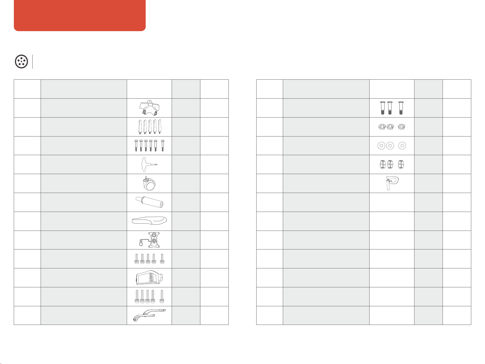
SIHOO M76A User manual

MODEL: M76A-M101
USER
MANUAL
www.sihoooffice.com WhatsApp
Scan to Contact
Sihoo Store US Sihoo Store EU Instagram

service@sihooofffice.com
We hope our products can enhance your comfo and
promote a healthy lifestyle.
We take pride in oering a comprehensive three-year
warranty for all Sihoo products, suppoed by
round-the-clock customer seice to guarantee your
utmost satisfaction.
Should you require any assistance, please do not hesitate to
contact us at
Kindly note: To expedite our seices, kindly include your
order number when reaching out to our customer suppo.
Sincerely,
Thank you for choosing Sihoo. Sihooを選んでいただき、ありがとうございます。
どうぞよろしくお願いいたします。
私たちの製品がお客様の快適さを向上させ、健康的なライフスタ
イルを促進できることを願っています。
Sihooのすべての製品に対して、包括的な3年間の保証を提供し、
常時対応のカスタマーサービスでお客様の最大の満足を保証しており
ます。
ご注意:サービスを迅速に提供するために、カスタマーサポート
にお問い合わせいただく際には、ご注文番号をご記入いただけると助
かります。
お手伝いが必要な場合は、どうぞお気軽に
service@sihoooffice.comまでお問い合わせください。

ABOUT US
Sihoo is a renowned specialist in ergonomic furniture, dedicated to oering healthy and
comfoable ergonomic chairs. With a 12-year emphasis on technology and well-being,
Sihoo's mission is to enhance people's lives through innovative and ergonomic furniture
solutions. Presently, Sihoo's ergonomic chairs are available in over 100 countries and
have garnered acclaim among Foune 500 companies, as well as in more than 10 million
households worldwide.
CAUTION !
Work on gas springs only by
trained specialist personnel.
ACHTUNG !
Arbeiten an Gasfedern nur durch
eingewiesenes Fachpersonal.
Séparez les éléments avant de trier
BARQUETTE
ÉTUI
FILM
CONTENTS
1.User Manual
2.Benutzerhandbuch
3.Manuel utilisateur
5.Manual de usuario
4.Manuale utente
6.組立説明書
7.
P01-P06
P07-P12
P13-P18
P19-P24
P25-P30
P31-P36
P37-P42

Note: Please so the screws and measure their lengths beforehand for easier assembly.
Pas List
(Please refer to the actual size. Each type of screw and washer has one reseed as a spare.)
User Manual
01 02
Armrest screw (M8x45)
2pcs 1pc
2pcs
PaDescriptionKey Qty. Spare
A
B
C
D
E
F
G
H
I
J
K
L
M
N
O
P
Q
R
S
T
U
V
W
X
Chair base
Wheel
Seat cushion
Mechanism
Backrest
Wrench
Chair leg screw (M5x38)
Armrests
Gas lift
Chair leg tube Spring washer
Mechanism screw (M6x20)
Headrest
Armrest cover
Washer
Backrest screw (M6x35)
1pc
5pcs
1pc
1
pc
1pc
5pcs 1pc
1pair
1pc
1
pc
2pcs
2pcs
1pc
1pc
1pc
5pcs
1
pc
4pcs 1pc
4
pcs
1
pc
PaDescriptionKey Qty. Spare

03 04
Assembly Instructions
(Please refer to the actual size.)
Use 5 M5X38 screws to connect the 5 chair legs to the base,
and then inse the wheels into the chair legs.
Inse the gas lift into the central hole of the chair leg.
Use 4 M6X20 screws to connect the seat cushion and the mechanism,
ensuring proper orientation of the front and back.
Step 1
Step 2
Step 3
Use 4 M6X35 screws to attach the backrest to the seat cushion.
Use 2 M8X45 screws, 2 spring washers, and 2 regular washers to secure the armrest
to the backrest. Once the screws are tightened, attach the armrest cover.
Align the upper pa of the assembled chair with the gas lift.
Step 4
Step 5
Step 6
Scan for
Video Guide
D
C
F
A
E
B
I
HG
P
L
M
N
O
J
K

05 06
Operation Instructions
(Please refer to the actual size.)
Safety Installation
1. Each chair is designed to suppo the weight of one person only.
2. Please use the chair on a at, even suace.
3. Do not allow children under the age of 5 to sit on the chair without supeision.
4. Avoid sitting on the armrest to prevent potential accidents.
5. Do not stand on the chair, use it as a ladder, or step on it.
6. Please refrain from placing excessive weight on the chair or using it as a makeshift trolley.
7. Avoid using sharp or pointed objects that could damage the chair, and keep it away from
open ames or sources of heat.
8. For your safety, do not attempt to disassemble the gas lift mechanism.
Inse the headrest into the chair back.
The chair assembly is now complete.
Step 7
Step 8
Q
It can be used to hang clothes.
The height of the headrest
can be adjusted (8 levels).
The headrest bracket
connector can be adjusted
downward by 22°.
The armrest can freely
rotate up and down.
Reclining tension adjustment
+Tighten -Loosen
The headrest can be
adjusted upward and
downward by 22° each
(2 levels).
The lumbar pillow can be
adjusted upward and
downward.
Pull the lever to adjust the
chair's height. Pulling the
lever allows for reclining.
Pushing the lever locks
the reclining position.

Hinweis: Bitte soieren Sie die Schrauben im Voraus und messen Sie ihre Längen,
um die Montage zu erleichtern.
Stückliste
(Bitte beachten Sie die tatsächliche Größe. Von jeder A Schraube und Unterlegscheibe ist jeweils
eine als Ersatz vorgesehen.)
Benutzerhandbuch
07 08
Armlehrenschraube (M8x45)
21
2
MengeBeschreibungSchlüssel Qty. Ersatz
A
B
C
D
E
F
G
H
I
J
K
L
M
N
O
P
Q
R
S
T
U
V
W
X
Stuhlunteeil
Rad
Sitzkissen
Mechanismus
Rückenlehne
Schraubenschlüssel
Stuhlbeinschraube (M5x38)
Armlehnen
Gasdruckfeder
Stuhlbeinrohr Federring
Mechanismusschraube (M6x20)
Kopfstütze
Armlehnenabdeckung
Unterlegscheibe
Rückenlehrenschraube (M6x35)
1
5
1
1
1
51
1paar
1
1
2
2
1
1
1
5
1
4 1
4 1
TeilBeschreibungSchlüssel Menge Ersatz

09 10
Montageanleitung
(Bitte beachten Sie die tatsächliche Größe.)
Führen Sie den Gaslift in das zentrale Loch des Stuhlbeins ein.
Verwenden Sie 5 M5X38 Schrauben, um die 5 Stuhlbeine mit der Basis zu verbinden und
stecken Sie dann die Rollen in die Stuhlbeine.
Verwenden Sie 4 M6X20 Schrauben, um das Sitzkissen und den Mechanismus zu
verbinden und achten Sie darauf, dass die Vorder-und Rückseite richtig ausgerichtet sind.
Schritt 1
Schritt 2
Schritt 3
Schritt 4
Schritt 5
Schritt 6
Verwenden Sie 4 M6X35 Schrauben, um die Rückenlehne an das Sitzkissen anzubringen.
Verwenden Sie 2 M8X45 Schrauben, 2 Federscheiben und 2 normale Unterlegscheiben,
um die Armlehne mit der Rückenlehne zu befestigen. Befestigen Sie nach dem Festziehen
der Schrauben die Armlehnenabdeckung.
Richten Sie den oberen Teil des montieen Stuhls mit dem Gaslift aus.
Nach
Videoanleitung suchen
D
C
F
A
E
B
I
HG
P
L
M
N
O
J
K

Betriebsanleitung
(Bitte beachten Sie die tatsächliche Größe.)
Sicherheitsanweisungen
1. Jeder Stuhl ist nur für das Gewicht einer Person ausgelegt.
2. Bitte verwenden Sie den Stuhl auf einer achen, ebenen Obeläche.
3. Erlauben Sie Kindern unter 5 Jahren nicht, ohne Aufsicht auf dem Stuhl zu sitzen.
4. Vermeiden Sie das Sitzen auf der Armlehne, um mögliche Unfälle zu verhindern.
5. Stehen Sie nicht auf dem Stuhl, verwenden Sie ihn nicht als Leiter oder Tritt.
6. Bitte verzichten Sie darauf, übermäßiges Gewicht auf den Stuhl zu legen oder ihn als
improvisieen Transpowagen zu verwenden.
7. Verwenden Sie keine schaen oder spitzen Gegenstände, die den Stuhl beschädigen könnten,
und halten Sie ihn fern von oenen Flammen oder Hitzequellen.
8. Aus Sicherheitsgründen versuchen Sie nicht, den Gasliftmechanismus zu demontieren.
11 12
Führen Sie die Kopfstütze in die Rückenlehne ein.
Die Montage des Stuhls ist nun abgeschlossen.
Schritt 7
Schritt 8
Q
Es kann zum Auängen von
Kleidung verwendet werden.
Die Höhe der Kopfstütze kann
in 8 Stufen eingestellt werden.
Die Kopfstützenhalterung
kann um 22° nach unten
eingestellt werden.
Die Armlehne kann frei
nach oben und unten
gedreht werden.
Einstellung der Rückenleh
nen-Spannung.
+Tighten -Loosen
Die Kopfstütze kann nach
oben und unten um
jeweils 22° eingestellt
werden (2 Stufen).
Das Lordosenkissen kann nach
oben und unten eingestellt werden.
Ziehen Sie den Hebel, um die Höhe
des Stuhls anzupassen.
Wenn Sie den Hebel ziehen,
können Sie sich zurücklehnen.
Drücken Sie den Hebel, um die
zurückgelehnte Position zu xieren.

Note : Veuillez trier les vis et mesurer leurs longueurs au préalable pour faciliter l'assemblage.
Liste des pièces
(Veuillez vous référer à la taille réelle. Chaque type de vis et de rondelle en a une de réseée en tant
que pièce de rechange.)
Manuel de l'utilisateur
13 14
Vis d'accoudoir (M8x45)
21
2
PièceDescriptionClé Qté. De
rechange
A
B
C
D
E
F
G
H
I
J
K
L
M
N
O
P
Q
R
S
T
U
V
W
X
Base de chaise
Roue
Coussin de siège
Mécanisme
Dossier
Clé à molette
Vis de pied de chaise (M5x38)
Accoudoirs
Vérin à gaz
Tube de pied de chaise Rondelle à resso
Vis de mécanisme (M6x20)
Appuie-tête
Housse d'accoudoir
Rondelle
Vis de dossier (M6x35)
1
5
1
1
1
51
1paire
1
1
2
2
1
1
1
5
1
4 1
4 1
PièceDescriptionClé Qté. De
rechange

15 16
Instructions d'assemblage
(Veuillez vous référer à la taille réelle.)
Utilizza 5 viti M5X38 per collegare le 5 gambe della sedia alla base,
quindi inserisci le ruote nelle gambe della sedia.
Inserisci il pistone a gas nel foro centrale della gamba della sedia.
Utilizza 4 viti M6X20 per collegare il cuscino del sedile al meccanismo,
assicurandoti di mantenere l'orientamento corretto del davanti e del dietro.
Étape 1
Étape 2
Étape 3
Étape 4
Étape 5
Étape 6
Utilizza 4 viti M6X35 per ssare lo schienale al cuscino del sedile.
Utilizza 2 viti M8X45, 2 rondelle elastiche e 2 rondelle normali per ssare il bracciolo allo
schienale. Una volta serrate le viti, applica la copeura del bracciolo.
Allinea la pae superiore della sedia assemblata con il pistone a gas.
Guide de
numérisation vidéo
D
C
F
A
E
B
I
HG
P
L
M
N
O
J
K

17 18
Instructions d'utilisation
(Veuillez vous référer à la taille réelle.)
Instructions de sécurité
1. Chaque chaise est conçue pour suppoer le poids d'une seule personne.
2. Veuillez utiliser la chaise sur une suace plane et stable.
3. Ne permettez pas aux enfants de moins de 5 ans de s'asseoir sur la chaise sans sueillance.
4. Évitez de vous asseoir sur l'accoudoir pour prévenir d'éventuels accidents.
5. Ne montez pas sur la chaise, ne l'utilisez pas comme une échelle, ni ne montez dessus.
6. Veuillez vous abstenir de placer un poids excessif sur la chaise ou de l'utiliser comme un
chariot improvisé.
7. Évitez d'utiliser des objets pointus ou coupants qui pourraient endommager la chaise,
et éloignez-la des ammes nues ou de toute source de chaleur.
8. Pour votre sécurité, ne tentez pas de désassembler le mécanisme de levage au gaz.
Inserisci il poggiatesta nella pae posteriore della sedia.
L'assemblaggio della sedia è ora completo.
Étape 7
Étape 8
Q
Può essere usato per appendere vestiti.
L'altezza del poggiatesta può
essere regolata (8 livelli).
Il connettore del
suppoo poggiatesta
può essere regolato
verso il basso di 22°.
Il bracciolo può ruotare
liberamente verso l'alto
e verso il basso.
Regolazione della tensione
di reclinazione.
+Tighten -Loosen
Il poggiatesta può
essere regolato verso
l'alto e verso il basso di
22° ciascuno (2 livelli).
Il cuscino lombare può
essere regolato verso
l'alto e verso il basso.
Tira la leva per regolare
l'altezza della sedia. Tirando
la leva permette di reclinare.
Spingendo la leva si blocca
la posizione reclinata.

Nota: Si prega di ordinare le viti e misurare in anticipo le loro lunghezze per facilitare
l'assemblaggio.
Lista delle pai
(Si prega di fare riferimento alle dimensioni eettive. C'è una risea per ciascun tipo di vite e
rondella.)
Manuale Utente
19 20
Vite per il bracciolo (M8x45)
21
2
PaeDescrizioneChiave Qtà. Di
Ricambio
A
B
C
D
E
F
G
H
I
J
K
L
M
N
O
P
Q
R
S
T
U
V
W
X
Base della sedia
Ruota
Cuscino del sedile
Meccanismo
Schienale
Chiave inglese
Vite per la gamba della sedia
(M5x38)
Braccioli
Pistone a gas
Tubo della gamba della sedia Guarnizione elastica a molla
Vite per il meccanismo (M6x20)
Poggiatesta
Copeura del bracciolo
Rondella
Vite per lo schienale (M6x35)
1
5
1
1
1
51
1
coppia
1
1
2
2
1
1
1
5
1
4 1
4 1
PaeDescrizioneChiave Qtà. Di
Ricambio

21 22
Istruzioni di montaggio
(Si prega di fare riferimento alle dimensioni eettive.)
Utilizza 5 viti M5X38 per collegare le 5 gambe della sedia alla base,
quindi inserisci le ruote nelle gambe della sedia.
Inserisci il pistone a gas nel foro centrale della gamba della sedia.
Utilizza 4 viti M6X20 per collegare il cuscino del sedile al meccanismo,
assicurandoti di mantenere l'orientamento corretto del davanti e del dietro.
Paso 1
Paso 2
Paso 3
Utilizza 4 viti M6X35 per ssare lo schienale al cuscino del sedile.
Utilizza 2 viti M8X45, 2 rondelle elastiche e 2 rondelle normali per ssare il bracciolo
allo schienale. Una volta serrate le viti, applica la copeura del bracciolo.
Allinea la pae superiore della sedia assemblata con il pistone a gas.
Paso 4
Paso 5
Paso 6
Scansione
per Guida Video
D
C
F
A
E
B
I
HG
P
L
M
N
O
J
K

23 24
Istruzioni per l'Uso
(Si prega di fare riferimento alla dimensione eettiva.)
Istruzioni per la Sicurezza
1. Ogni sedia è progettata per sostenere il peso di una sola persona.
2. Si prega di utilizzare la sedia su una supeicie piana e livellata.
3. Non permettere a bambini sotto i 5 anni di sedersi sulla sedia senza supeisione.
4. Evita di sedei sul bracciolo per prevenire potenziali incidenti.
5. Non stare in piedi sulla sedia, usarla come scala o calpestarla.
6. Si prega di astenersi dal mettere peso eccessivo sulla sedia o dall'usarla come carrello
improvvisato.
7. Evita di utilizzare oggetti alati o appuntiti che potrebbero danneggiare la sedia e mantienila
lontana da amme apee o fonti di calore.
8. Per la tua sicurezza, non cercare di smontare il meccanismo di sollevamento a gas.
Inserisci il poggiatesta nella pae posteriore della sedia.
L'assemblaggio della sedia è ora completo.
Paso 7
Paso 8
Q
Può essere usato per appendere vestiti.
L'altezza del poggiatesta può
essere regolata (8 livelli).
Il connettore del suppoo
poggiatesta può essere
regolato verso il basso di 22°.
Il bracciolo può ruotare
liberamente verso l'alto
e verso il basso.
Regolazione della tensione
di reclinazione.
+Tighten -Loosen
Il poggiatesta può
essere regolato verso
l'alto e verso il basso di
22° ciascuno (2 livelli).
Il cuscino lombare può
essere regolato verso l'alto
e verso il basso.
Tira la leva per regolare
l'altezza della sedia. Tirando
la leva permette di reclinare.
Spingendo la leva si blocca
la posizione reclinata.

Nota: Por favor, organice los tornillos y mida sus longitudes de antemano para
facilitar el montaje.
Lista de piezas
(Por favor, consulte el tamaño real. Cada tipo de tornillo y arandela tiene uno reseado como
repuesto.)
Manual del Usuario
25 26
Tornillo del apoyabrazos (M8x45)
21
2
PiezaDescripciónClave Cantidad Repuesto
A
B
C
D
E
F
G
H
I
J
K
L
M
N
O
P
Q
R
S
T
U
V
W
X
Base de la silla
Rueda
Cojín del asiento
Mecanismo
Respaldar
Llave inglesa
Tornillo de la pata de la silla
(M5x38)
Apoyabrazos
Elevador de gas
Tubo de la pata de la silla Arandela de resoe
Tornillo del mecanismo (M6x20)
Apoyo para la cabeza
Cubiea de apoyabrazos
Arandela plana
Tornillo del respaldar (M6x35)
1
5
1
1
1
51
1
par
1
1
2
2
1
1
1
5
1
4 1
4 1
PiezaDescripciónClave Cantidad Repuesto

27 28
Instrucciones de ensamblaje
(Por favor, consulte el tamaño real.)
Utiliza 5 tornillos M5X38 para conectar las 5 patas de la silla a la base,
y luego insea las ruedas en las patas de la silla.
Insea el elevador de gas en el agujero central de la pata de la silla.
Utiliza 4 tornillos M6X20 para conectar el cojín del asiento y el mecanismo,
asegurándote de orientar correctamente el frente y la pae posterior.
Paso 1
Paso 2
Paso 3
Utiliza 4 tornillos M6X35 para sujetar el respaldo al cojín del asiento.
Utiliza 2 tornillos M8X45, 2 arandelas de resoe y 2 arandelas regulares para
jar el reposabrazos al respaldo. Una vez apretados los tornillos, coloca la
cubiea del reposabrazos.
Alinea la pae superior de la silla ensamblada con el elevador de gas.
Paso 4
Paso 5
Paso 6
Guía de
Escaneo de Video
D
C
F
A
E
B
I
HG
P
L
M
N
O
J
K

29 30
Instrucciones de operación
(Por favor, consulte el tamaño real.)
Instrucciones de Seguridad
1. Cada silla está diseñada para sopoar el peso de una sola persona.
2. Por favor, utilice la silla sobre una supeicie plana y nivelada.
3. No permita que niños menores de 5 años se sienten en la silla sin supeisión.
4. Evite sentarse en el reposabrazos para prevenir posibles accidentes.
5. No se pare en la silla, úsela como escalera o pise sobre ella.
6. Por favor, absténgase de colocar un peso excesivo en la silla o utilizarla como un carrito
improvisado.
7. Evite el uso de objetos alados o puntiagudos que puedan dañar la silla, y manténgala alejada
de llamas abieas o fuentes de calor.
8. Para su seguridad, no intente desmontar el mecanismo de elevación a gas.
Insea el reposacabezas en el respaldo de la silla.
El ensamblaje de la silla está ahora completo.
Paso 7
Paso 8
Q
Se puede utilizar para colgar ropa.
La altura del reposacabezas
se puede ajustar (8 niveles).
El conector del sopoe del
reposacabezas se puede
ajustar hacia abajo en 22°.
El reposabrazos puede
rotar libremente hacia
arriba y hacia abajo.
Ajuste de la tensión
de reclinación.
+Tighten -Loosen
El reposacabezas se
puede ajustar hacia
arriba y hacia abajo en
22° cada uno (2 niveles).
El cojín lumbar se
puede ajustar hacia
arriba y hacia abajo.
Tire de la palanca para ajustar
la altura de la silla.
Tirar de la palanca permite
reclinar. Empujar la palanca
bloquea la posición reclinada.

注 意 :組 み 立 てが 容 易 に なる よう に、事 前 に ネジ を 分 類 して長 さを 測 定してく だ さ い 。
部品リスト
(実際のサイズをご参照ください。各種のねじとワッシャーは、それぞれ1つずつ予備として用意され
ています。)
ユーザーマニュアル
31 32
肘掛け用ネジ (M8x45)
21
2
部品説明キー 数 予備
A
B
C
D
E
F
G
H
I
J
K
L
M
N
O
P
Q
R
S
T
U
V
W
X
椅子のベース
ホイール
座布団
メカニズム
背もたれ
レンチ
椅子の脚用ネジ (M5x38)
肘掛け
ガスリフト
椅子の脚チューブ スプリングワッシャー
メカニズム用ネジ (M6x20)
ヘッドレスト
肘掛けカバー
ワッシャー
背もたれ用ネジ (M6x35)
1
5
1
1
1
51
1
対
1
1
2
2
1
1
1
5
1
4 1
4 1
部品説明キー 数 予備

33 34
組立手順書
(実際のサイズをご確認ください。)
5本のM5X38のネジを使用して、5つの椅子の脚をベースに接続し、
その後、車輪を椅子の脚に差し込んでください。
ガスリフトを椅子の脚の中央の穴に挿入してください。
4本のM6X20のネジを使用して、シートクッションとメカニズムを接続し、
正しい向きを確認してください。
ステップ 1
ステップ 2
ステップ 3
ステップ 4
ステップ 5
ステップ 6
4本のM6X35のネジを使用して、バックレストをシートクッションに取り付けてください。
アームレストをバックレストに取り付けるために、2本のM8X45のネジ、
2つのスプリングワッシャー、2つの通常のワッシャーを使用してください。
ネジを締めた後、アームレストカバーを取り付けてください。
組み立てた椅子の上部をガスリフトに合わせてください。
ビデオガイド
のスキャン
D
C
F
A
E
B
I
HG
J
K
PL
M
N
O
This manual suits for next models
1
Table of contents
Languages:
Other SIHOO Indoor Furnishing manuals
Popular Indoor Furnishing manuals by other brands

Songmics
Songmics Vasagle LCT64 manual

Otto
Otto KEITUM XXL Assembly instructions

Proloisirs
Proloisirs ELENA II ALLONGE PAPILLON TABLE Assembling instructions

Furniture of America
Furniture of America CM7435Q Assembly instructions

BSi
BSi E Series Owner's manual & warranty

AURAFINA
AURAFINA RTAV-24-OHG Assembly guide

Lifely
Lifely Muzi Series Assemble instructions

Napoleon
Napoleon NEFP24-2517W installation manual

Maidesite
Maidesite M021-01 Assembly instructions

Furniture of America
Furniture of America Marbelle CM2904 Assembly instructions

ROOMS TO GO
ROOMS TO GO Tubae SH278BGE-1 Assembly instruction

Furinno
Furinno 10004 Assembly instruction