Silverline 546534 User manual

Version date: 28.09.18 silverlinetools.com
Register online: silverlinetools.com
3
GUARANTEE
YEAR
ANS DE GARANTIE
JAHRE GARANTIE
AÑOS DE GARANTÍA
ANNI DI GARANZIA
JAAR GARANTIE
LATA GWARANCJI
XXXXXX
546534
FR Scie à onglets coulissante 1450 W
DE Kapp- und Gehrungssäge, 1450 W (Heimwerkermodell)
ES Sierra ingletadora telescópica 210 mm,1450 W
IT Troncatrice 1450 W
NL 1450 W schuifverstekzaag
PL Ukośnicazposuwem1450W
DIY 1450W Sliding Mitre Saw 210mm
546534_Manual.indd 1 28/09/2018 16:16

2
1
6
2
40
3
38 4
5
37
42
44 18
17
16
15
14
13
12
11
10
9
8
7
24
25
34
39
26
27 28
29
30
31
32
19
20
36
21
33
35
18
22
43
23 41
546534_Manual.indd 2 28/09/2018 16:16

silverlinetools.com 3
English ................08
Français ...............16
Deutsch................26
Español................36
Italiano................44
Nederlands ..........52
Polski ..................60
546534_Manual.indd 3 28/09/2018 16:16

4
ABC
DEF
GHI
JKL
546534_Manual.indd 4 28/09/2018 16:16

silverlinetools.com 5
MNO
PQR
STU
VWX
546534_Manual.indd 5 28/09/2018 16:16

6
150mm
150mm
150mm
FIG.I FIG.II
FIG.III FIG.IV
546534_Manual.indd 6 28/09/2018 16:16

silverlinetools.com 7
546534_Manual.indd 7 28/09/2018 16:16

GB
8
Voltage:............................................................230V~ 50Hz
Power: ..................................................................1450W
No load speed:.........................................................5000rpm
Max depth of cut:.........................................................62mm
Max blade size:.........................................................Ø210mm
Blade bore: .............................................................Ø30mm
Supplied blade: ...........................................Ø210 x 30 x 2.8mm 24T
Mitre table angles:....................................................-45 to +45°
Bevel cuts:................................................................ 0-45°
Straight cut:
0° mitre x 0° bevel...................................................170 x 60mm
Mitre cut:
45° (L&R) x 0° . . . . . . . . . . . . . . . . . . . . . . . . . . . . . . . . . . . . . . . . . . . . . . . . . . . . . . .120 x 60mm
Bevel cut:
0° mitre x bevel (L) 45° ...............................................170 x 34mm
45° mitre (L&R) x bevel (L) 45°.........................................120 x 34mm
Laser Class: ...................................................................II
Laser Wavelength: . . . . . . . . . . . . . . . . . . . . . . . . . . . . . . . . . . . . . . . . . . . . . . . . . . . . . . . .650nm
Laser Output power: .....................................................≤1mW
Power cord length:...........................................................2m
Protection class: .............................................................
Ingress protection:..........................................................IP20
Dimensions (L x W x H):........................................ 380 x 340 x 420mm
Weight: .................................................................7.23kg
Aspartofourongoingproductdevelopment,specicationsof
Silverline products may alter without notice.
Sound and vibration information:
Sound pressure LPA ....................................................96.54dB(A)
Sound power LWA.....................................................109.54dB(A)
Uncertainty K ...............................................................3dB
The sound intensity level for the operator may exceed 85dB(A)
and sound protection measures are necessary.
Technical Abbreviations Key
Specication
WARNING: Always wear ear protection where the sound level exceeds 85dB(A) and limit
the time of exposure if necessary. If sound levels are uncomfortable, even with ear protection, stop
usingthetoolimmediatelyandchecktheearprotectioniscorrectlyttedandprovidesthecorrect
level of sound attenuation for the level of sound produced by your tool.
WARNING: User exposure to tool vibration can result in loss of sense of touch, numbness,
tingling and reduced ability to grip. Long-term exposure can lead to a chronic condition.If necessary,
limit the length of time exposed to vibration and use anti-vibration gloves. Do not operate the tool
with hands below a normal comfortable temperature, as vibration will have a greater effect. Use the
guresprovidedinthespecicationrelatingtovibrationtocalculatethedurationandfrequency
of operating the tool.
Description of Symbols
The rating plate on your tool may show symbols.These represent important information about the
product or instructions on its use.
Wear hearing protection.
Wear eye protection.
Wear breathing protection.
Wear head protection.
Wear hand protection.
Read instruction manual.
Toxic fumes or gases!
LASER warning!
Be aware of kickback!
Warning: Sharp blades or teeth!
DO NOTuse in rain or damp environments!
Class II construction (double insulated for additional protection)
Environmental Protection
Waste electrical products should not be disposed of with household waste. Please
recycle where facilities exist. Check with your local authority or retailer for recycling
advice.
Conforms to relevant legislation and safety standards.
Caution!
Always disconnect from the power supply when adjusting, changing accessories,
cleaning, carrying out maintenance and when not in use!
Do not touch the blades before the machine is disconnected from the supply and the
blades have come to complete stop.
Dustextractionrequiredorrecommended
VVolts
~, AC Alternating current
A, mA Ampere, milli-Amp
n0 No load speed
°Degrees
ØDiameter
Hz Hertz
W, kW Watt, kilowatt
/min or min-1 Operations per minute
rpm Revolutions per minute
dB(A) Decibel sound level (A weighted)
Introduction
Thank you for purchasing this Silverline tool.This manual contains information necessary
forsafeandeffectiveoperationofthisproduct.Thisproducthasuniquefeaturesand,evenif
you are familiar with similar products, it is necessary to read this manual carefully to ensure
you fully understand the instructions. Ensure all users of the tool read and fully understand
this manual.
Original Instructions
546534_Manual.indd 8 28/09/2018 16:16

DIY 1450W Sliding Mitre Saw546534
9
silverlinetools.com
Soundandvibrationlevelsinthespecicationaredeterminedaccordingtointernationalstandards.
Theguresrepresentnormaluseforthetoolinnormalworkingconditions.Apoorlymaintained,
incorrectly assembled, or misused tool,may produce increased levels of noise and vibration.
www.osha.europa.eu provides information on sound and vibration levels in the workplace that
may be useful to domestic users who use tools for long periods of time.
Carefully read and understand this manual and any label attached to the tool before use. Keep these
instructions with the product for future reference.Ensure all persons who use this product are fully
acquaintedwiththismanual.
Even when used as prescribed it is not possible to eliminate all residual risk factors.Use with
caution. If you are at all unsure of the correct and safe manner in which to use this tool, do not
attempt to use it.
General Power Tool Safety Warnings
WARNING: Read all safety warnings, instructions, illustrations and specications
provided with this power tool. Failure to follow all instructions listed below may result in electric
shock,reand/orseriousinjury.
Save all warnings and instructions for future reference.
The term “power tool” in the warnings refers to your mains-operated (corded) power tool or battery-
operated (cordless) power tool.
1) Work area safety
a) Keep work area clean and well lit.Cluttered or dark areas invite accidents.
b) Do not operate power tools in explosive atmospheres, such as in the presence of
ammable liquids, gases or dust. Power tools create sparks which may ignite the dust or
fumes.
c) Keep children and bystanders away while operating a power tool.Distractions can cause
you to lose control.
2) Electrical safety
a) Power tool plugs must match the outlet.Never modify the plug in any way. Do not use
any adapter plugs with earthed (grounded) power tools. Unmodiedplugsandmatching
outlets will reduce risk of electric shock.
b) Avoid body contact with earthed or grounded surfaces, such as pipes,radiators, ranges
and refrigerators. There is an increased risk of electric shock if your body is earthed or
grounded.
c) Do not expose power tools to rain or wet conditions. Water entering a power tool will
increase the risk of electric shock.
d) Do not abuse the cord. Never use the cord for carrying,pulling or unplugging the power
tool. Keep cord away from heat,oil, sharp edges or moving parts. Damaged or entangled
cords increase the risk of electric shock.
e) When operating a power tool outdoors, use an extension cord suitable for outdoor use.
Use of a cord suitable for outdoor use reduces the risk of electric shock.
f) If operating a power tool in a damp location is unavoidable, use a residual current device
(RCD) protected supply.Use of an RCD reduces the risk of electric shock.
3) Personal safety
a) Stay alert, watch what you are doing and use common sense when operating a power
tool. Do not use a power tool while you are tired or under the inuence of drugs, alcohol
or medication. A moment of inattention while operating power tools may result in serious
personal injury.
b) Use personal protective equipment. Always wear eye protection.Protectiveequipment
such as a dust mask, non-skid safety shoes,hard hat or hearing protection used for appropriate
conditions will reduce personal injuries.
c) Prevent unintentional starting.Ensure the switch is in the OFF-position before connecting
to power source and/or battery pack, picking up or carrying the tool.Carrying power
toolswithyourngerontheswitchorenergisingpowertoolsthathavetheswitchONinvites
accidents.
d) Remove any adjusting key or wrench before turning the power tool ON.A wrench or a key
left attached to a rotating part of the power tool may result in personal injury.
e) Do not overreach. Keep proper footing and balance at all times.This enables better control
of the power tool in unexpected situations.
f) Dress properly. Do not wear loose clothing or jewellery.Keep your hair and clothing away
from moving parts. Loose clothes,jewellery or long hair can be caught in moving parts.
g) If devices are provided for the connection of dust extraction and collection facilities,
ensure these are connected and properly used. Use of dust collection can reduce dust-related
hazards.
h) Do not let familiarity gained from frequent use of tools allow you to become complacent
and ignore tool safety principles. Acareless action can cause severe injury within a fraction of a
second.
4) Power tool use and care
a) Do not force the power tool. Use the correct power tool for your application.The correct
power tool will do the job better and safer at the rate for which it was designed.
b) Do not use the power tool if the switch does not turn it ON and OFF. Any power tool that
cannot be controlled with the switch is dangerous and must be repaired.
c) Disconnect the plug from the power source and/or remove the battery pack,if detachable,
from the power tool before making any adjustments, changing accessories,or storing
power tools. Such preventive safety measures reduce the risk of starting the power tool
accidentally.
d) Store idle power tools out of the reach of children and do not allow persons unfamiliar
with the power tool or these instructions to operate the power tool. Power tools are
dangerous in the hands of untrained users.
e) Maintain power tools and accessories. Check for misalignment or binding of moving
parts, breakage of parts and any other condition that may affect the power tool’s
operation. If damaged, have the power tool repaired before use. Many accidents are caused
by poorly maintained power tools.
f) Keep cutting tools sharp and clean. Properly maintained cutting tools with sharp cutting edges
are less likely to bind and are easier to control.
g) Use the power tool, accessories and tool bits,etc. in accordance with these instructions,
taking into account the working conditions and the work to be performed. Use of the
power tool for operations different from those intended could result in a hazardous situation.
h) Keep handles and grasping surfaces dry, clean and free from oil and grease.Slippery
handles and grasping surfaces do not allow for safe handling and control of the tool in
unexpected situations.
5)
a) Service Haveyourpowertoolservicedbyaqualiedrepairpersonusingonlyidentical
replacement parts.This will ensure that the safety of the power tool is maintained.
Specic Safety
Mitre Saw Safety
WARNING: Before connecting a tool to a power source (mains switch power point
receptacle, outlet, etc.) be sure that the voltage supply is the same as that specied on the
rating label of the tool. Apowersourcewithavoltagegreaterthanthatspeciedforthetoolcan
result in serious injury to the user,and damage to the tool. If in doubt, do not plug in the tool. Using
a power source with a voltage less than the nameplate rating is harmful to the motor.
WARNING!
• Hold the power tool by insulated gripping surfaces only,when performing an operation
where the cutting tool may contact its own cord. Contact with a “live” wire will also make
exposed metal parts of the power tool “live” and could give the operator electric shock.
• Always use blades with correct size and shape (diamond versus round) of arbour holes.
Blades that do not match the mounting hardware of the saw will run eccentrically,causing loss
of control.
• Never use damaged or incorrect blade washers or bolt. The blade washers and bolt were
specially designed for your saw,for optimum performance and safety of operation.
• Keep hands away from cutting area and the blade.
IMPORTANT: If you are unsure about operating this tool after reading these instructions,please
seek additional training.
a) Do not allow anyone under the age of 18 years to operate this saw
b) When operating the saw, use safety equipment including safety goggles or shield, ear
protection, dust mask and protective clothing including safety gloves
c) Power tools may produce vibration.Vibration can cause disease. Gloves may help to maintain
goodbloodcirculationinthengers.Hand-heldtoolsshouldnotbeusedforlongperiods
without a break
d) Whenever possible, use a vacuum dust extraction system to control dust/waste
e) Do not attempt to cut material thicker than detailed in the Specications section of this
manual
f) Mitre saws are not designed for general cutting of rewood. Always ensure wood is dry with
suitableatsurfaces,soitissecurelyheldonthemitretableandfence
g) Only guide the saw blade against the workpiece when the tool is switched on. Otherwise
there is a risk of kickback when the blade becomes wedged in the workpiece
h) Adjust the cutting depth to the thickness of the workpiece
i) Never remove dust, chips or waste by hand close to the blade.Ensure the tool is unpowered
and use a suitable brush
j) Only use saw blades recommended by the manufacturer that conform to EN 847-1 or
equivalent standard in your country
k) Keep rags, cloths and string away from the work area and ensure the operator’s clothing
has no loose strands of material that could become caught in the rotating blade, causing
injury. Gloves worn by the operator must not have loose strands
l) Ensure the mitre saw is operated without risk of items stored above falling onto the tool.
Vibration of the tool may cause nearby stored items to move
m) Keep saw blades not tted to the tool in a suitable container to protect against cuts -
especially when carrying
546534_Manual.indd 9 28/09/2018 16:16

GB
10
n) Always ensure the saw blade is suitable for the material being cut and that the maximum
rpm of the blade is not exceeded by the maximum no load speed of the saw
o) When using blades with a larger bore than the mitre saw spindle ensure the correct size
bore spacer (spindle ring) is used
p) When transporting the saw,ensure its own transport handle is used (not the operating
handle) and that the saw is in the locked down position
q) Do not remove cut-off material or swap the workpiece without rst returning the saw
head to the top position with the guard closed
r) Ensure work is correctly supported. Large panels may sag under their own weight and
bind the saw blade. Supports must be placed under the panel on both sides, close to the line of
cut and near the edge of the panel
s) Ensure all supports and power cables are completely clear of the cutting path
t) Always secure the workpiece to a stable platform, ensuring body exposure is minimised,
avoiding blade binding, or loss of control
u) Do not stand in line with the saw blade of the mitre saw in use. Stand to the side to avoid
possible kickback
v) Note the direction of rotation of the motor and the blade
w) Inspect the workpiece and remove all nails and other embedded objects prior to starting
work
x) Do not apply any sideways or twisting force to the blade whilst cutting
y) If a cut does not extend to the edge of the workpiece, or if the blade binds in the cut,
allow the blade to come to a complete stop and lift the saw out of the workpiece
z) Do not attempt to free a jammed blade before rst disconnecting the machine from power
1. Beware of projected waste.In some situations, waste material may be projected at speed from
the cutting tool. It is the user’s responsibility to ensure that other people in the work area are
protected from the possibility of projected waste
2. If you are interrupted when operating the saw,complete the process and switch off before
diverting your attention
3. Check the lower guard for proper closing before each use. Do not operate the saw if the lower
guard does not move freely and close instantly.Never clamp or tie the lower guard into the open
position. If the saw is accidentally dropped, the lower guard may be bent.Raise the lower guard
with the retracting handle and make sure it moves freely and does not touch the blade or any
other part, in all angles and depths of cut
4. Neveroperatethesawwithouttheguardstted
5. Periodicallycheckthatallnuts,boltsandotherxingshavenotloosened,tightenwhere
necessary
6. Do not use blades of High Speed Steel (HSS blades)
7. If the table insert is damaged or worn,have it replaced by a power tool repairer.
The tool must be used only for its prescribed purpose. Any use other than those mentioned in
this manual will be considered a case of misuse. The user, and not the manufacturer,shall be liable
for any damage or injury resulting from such cases of misuse.
Themanufacturershallnotbeliableforanymodicationsmadetothetoolnorforanydamage
resultingfromsuchmodications.Evenwhenthetoolisusedasprescribeditisnotpossibleto
eliminate all residual risk factors.
Further safety instructions for all saws
Kickback causes & related warnings
– kickback is a sudden reaction to a pinched, bound or misaligned saw blade,causing an
uncontrolled saw to lift up and out of the workpiece toward the operator;
– when the blade is pinched or bound tightly by the kerf closing down, the blade stalls and the
motor reaction drives the unit rapidly back toward the operator;
– if the blade becomes twisted or misaligned in the cut, the teeth at the back edge of the blade
can dig into the top surface of the wood causing the blade to climb out of the kerf and jump back
toward the operator.
Kickback is the result of saw misuse and/or incorrect operating procedures or conditions and
can be avoided by taking proper precautions as given below.
a) Maintain a rm grip with both hands on the saw and position your arms to resist kickback
forces. Position your body to either side of the blade, but not in line with the blade.
Kickback could cause the saw to jump backwards, but kickback forces can be controlled by the
operator if proper precautions are taken.
b) When blade is binding, or when interrupting a cut for any reason,release the trigger and
hold the saw motionless in the material until the blade comes to a complete stop. Never
attempt to remove the saw from the work or pull the saw backward while the blade is in
motion or kickback may occur. Investigate and take corrective actions to eliminate the cause of
blade binding.
c) When restarting a saw in the workpiece, centre the saw blade in the kerf and check that
saw teeth are not engaged into the material. If saw blade is binding, it may walk up or
kickback from the workpiece as the saw is restarted.
d) Support large panels to minimise the risk of blade pinching and kickback. Large panels
tend to sag under their own weight. Supports must be placed under the panel on both sides,
near the line of cut and near the edge of the panel.
e) Do not use dull or damaged blades. Unsharpened or improperly set blades produce narrow
kerf causing excessive friction, blade binding and kickback.
f) Blade depth and bevel adjusting locking levers must be tight and secure before making
cut. If blade adjustment shifts while cutting, it may cause binding and kickback.
g) Use extra caution when sawing into existing walls or other blind areas.The protruding
blade may cut objects that can cause kickback.
Lower guard function
a) Check lower guard for proper closing before each use.Do not operate the saw if lower
guard does not move freely and close instantly.Never clamp or tie the lower guard into
the open position. If saw is accidentally dropped, lower guard may be bent.Raise the lower
guard with the retracting handle and make sure it moves freely and does not touch the blade or
any other part, in all angles and depths of cut.
b) Check the operation of the lower guard spring. If the guard and the spring are not
operating properly,they must be serviced before use. Lower guard may operate sluggishly
due to damaged parts, gummy deposits,or a build-up of debris.
c) Lower guard may be retracted manually only for special cuts such as "plunge cuts" and
"compound cuts". Raise lower guard by retracting handle and as soon as blade enters the
material, the lower guard must be released.For all other sawing, the lower guard should operate
automatically.
d) Always observe that the lower guard is covering the blade before placing saw down on
bench or oor.An unprotected, coasting blade will cause the saw to walk backwards, cutting
whatever is in its path. Be aware of the time it takes for the blade to stop after switch is released.
Guard function
a) Check guard for proper closing before each use.Do not operate the saw if guard does
not move freely and enclose the blade instantly.Never clamp or tie the guard so that the
blade is exposed. If saw is accidentally dropped, guard may be bent.Check to make sure that
guard moves freely and does not touch the blade or any other part, in all angles and depths of
cut.
b) Check the operation and condition of the guard return spring. If the guard and the spring
are not operating properly, they must be serviced before use.Guard may operate sluggishly
due to damaged parts, gummy deposits,or a build-up of debris.
c) Assure that the base plate of the saw will not shift while performing the “plunge cut”
when the blade bevel setting is not at 90°. Blade shifting sideways will cause binding and
likely kick back.
d) Always observe that the guard is covering the blade before placing saw down on bench or
oor. An unprotected, coasting blade will cause the saw to walk backwards,cutting whatever is in
its path. Be aware of the time it takes for the blade to stop after switch is released.
Laser Safety
ThelaserusedinthisdeviceisaClass2laserwithmaximumpowerof≤1mWandawavelength
of 400-700nm.
These lasers do not normally present an optical hazard, although staring at the beam may cause
ashblindness.
WARNING: Avoid direct eye contact.
A hazard may exist if you deliberately stare into the beam,please observe all safety rules as follows:
• The laser shall be used and maintained in accordance with the manufacturer’s instructions
• Do not switch on the laser light until the tool is ready to cut
• Never aim the beam at any person, and particularly not into the eyes of any person or animal, or
any object other than the workpiece
• Alwaysensurethelaserbeamisaimedatasturdyworkpiecewithoutreectivesurfaces.i.e.wood
orrough-coatedsurfacesareacceptable.Reectivesheetsteelorsimilarisnotsuitableforlaser
useasthereectivesurfacecoulddirectthebeambackattheoperator
Do not change the laser light assembly.Repairs must only be carried out by the laser manufacturer
or an authorised agent. DO NOT exchange with a different type of laser
CAUTION: Useofcontrolsoradjustmentsorperformanceofproceduresotherthanthosespecied
herein may result in hazardous radiation exposure.
Please refer to the relevant EN standards,EN60825-1:2007 for more information on Lasers.
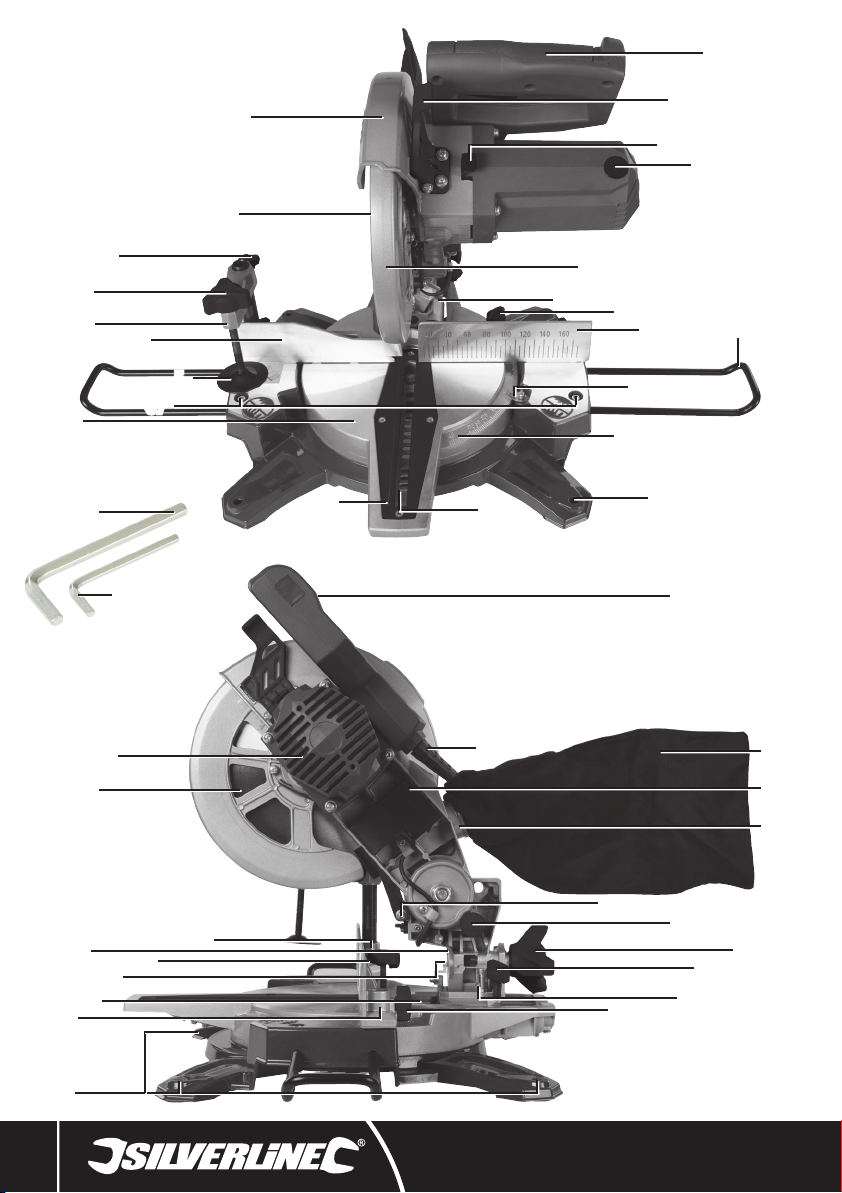
Product Familiarisation
1. Blade Guard
2. Workpiece Clamp Adjustment Locking Knob
3. Workpiece Clamping Screw
4. Sliding Fence
5. Workpiece Clamping Plate
6. Blade Channel
7. Operating Handle
8. Blade Guard Safety Latch
9. Spindle Lock Button
10. Brush Access Cover
546534_Manual.indd 10 28/09/2018 16:16

DIY 1450W Sliding Mitre Saw546534
11
silverlinetools.com
11. Lower Blade Guard
12. Slide Rails Mechanism
13. Mitre Lock
14. Fixed Fence
15. Workpiece Supports
16. Mitre Angle Indicator
17. Mitre Angle Gauge
18. Bench Mounting Holes
19. 6mm Hex Key
20. 4mm Hex Key
21. Motor Vents
22. Bevel Angle Gauge
23. Workpiece Clamp Slot
24. ON/OFF Trigger Switch
25. Power Cord
26. Dust Collection Bag
27. Laser
28. Cutting Head Latching Pin
29. Bevel Locking Knob
30. Slide Rails Locking Knob
31. Bevel Stop/Calibration Screw
32. Workpiece Clamp Locking Knob
33. Sliding Fence Screw
34. Laser ON/OFF Switch
35. Fence Alignment Screw
36. Blade
37. Workpiece Support Screws
38. Workpiece Clamp
39. Dust Extraction Port
40. Arbor Bolt
41. Slide Rails
42. Mitre Table
43. Bevel Angle Indicator
44. Throat Plate
Intended Use
Mains powered bench-mounted or portable sliding mitre saw for cutting through wood and other
materials. Performs straight and bevel cuts.The included saw blade is suitable for natural wood and
articialcompositewoodmaterials.
Note: For non-commercial use only.
Unpacking Your Tool
• Carefully unpack and inspect your product. Fully familiarise yourself with all its features and
functions
• Ensure all parts of the product are present and in good condition. If any parts are missing or
damaged, have such parts replaced before attempting to use this product
Before Use
WARNING: Important safety devices! Ensure correct function, maintain in accordance with
instructions and DO NOTdisable!
WARNING: Ensure the tool is disconnected from the power supply before attaching or
changing accessories, or making any adjustments.
Note:Cutter/cuttingheadisadescriptionofthesectionofthetoolincorporatingthemotor,blade
assembly and pivoting arm. On a sliding mitre saw it is the section that traverses the pole arm or
arms.
Bench mounting
IMPORTANT: It is recommended to mount the saw to a bench or board.Although the saw can be
used without mounting to a bench or board, there is a greater risk to safety during use.
1. Mount the saw to a level, horizontal bench or work table using bolts, washers and locking nuts
(not supplied) through the four Bench Mounting Holes (18)
2. DO NOT over-tighten; this may damage the base
3. DonotuseboltsthatarenotagoodtfortheBenchMountingHoles;thismayencourage
unwanted movement
4. Alternatively, mount the saw on 13mm or thicker board, and clamp the board to a work support
(Fig. I); this makes it easy to relocate the saw, clamping it to a work support wherever needed
5. When using a board it may be necessary to countersink the washers and nuts so the board is
level on the surface
WARNING: Ensure the mounting surface is not warped; an uneven surface can cause binding
and inaccurate sawing.
Unlatching & raising the Cutting Head
WARNING: ALWAYS ensure the tool is unplugged from the power socket and the blade has
cometoacompletestopbeforelatchingthecuttingheaddown,carryingthetool,and/orunlatching
the cutting head.
To unlatch & raise the Cutting Head:
1. Press down on the Operating Handle (7) (Image A) and pull out the Cutting Head Latching Pin
(28) (Image B)
2. Slowly raise the saw’s cutting head (Image C)
To lower & latch the Cutting Head:
1. From the raised position, disengage the Blade Guard Safety Latch (8) (Image D)
2. Press the Operating Handle (7) and cutting head down slowly (Image A) then press in the Cutting
Head Latching Pin (28)
Adjusting the Fence
1. Ensure the Fence (4 & 14) is used with every cut
2. The Sliding Fence (4) can be adjusted and extended out or removed entirely
3. To adjust the Sliding Fence loosen the Sliding Fence Screw (33) using the 4mm Hex Key (20) and
slidetheFencetotherequiredposition(ImageE)
4. Tighten the Sliding Fence Screw using the 4mm Hex Key to secure the Sliding Fence
Note:IftheWorkpieceClampIsattachedtothesawontheSlidingFenceitwillrequireremoving
before Fence adjustment can take place.
5. If performing a bevel cut,the Sliding Fence may need to be removed so it does not obstruct the
movement of the cutting head or interfere with the Blade (36) when tilted
WARNING: NEVER use the mitre saw without the Fixed Fence.
Adjusting the Workpiece Supports
1. Loosen the Workpiece Support Screws (37) using the 4mm Hex Key (20)
2. Slide the Workpiece Supports (15) into the holes on the side of the tool (Image F)
3. Tighten the Workpiece Support Screws to secure the Workpiece Supports in position
Fitting the Workpiece Clamp
1. Decide which side of the cutting head that the workpiece is to be clamped (normally the longer
side of the workpiece protruding from the tool)
2. Insert the Workpiece Clamp (38) fully into the desired Workpiece Clamp Slot (23) (Image G)
3. Tighten the Workpiece Clamp Locking Knob (32)
4. Position the Clamp over the workpiece by swivelling the upper part of the Clamp and raise or
lower the Clamp according to the size of the workpiece (Image H)
5. Once the clamp is in position tighten the Workpiece Clamp Adjustment Locking Knob (2)
6. Screw the Workpiece Clamping Screw (3) clockwise to lower the Workpiece Clamping Plate (5)
onto the workpiece to clamp in position (Image I)
546534_Manual.indd 11 28/09/2018 16:16

GB
12
Dust Extraction
1. Optimal dust extraction is achieved by connecting a dust extraction system or vacuum cleaner to
theDustExtractionPort(39).Adustportadaptor(notsupplied)mayberequiredtohelpconnect
the dust extraction system to the Dust Port
2. TheDustCollectionBag(26)tsdirectlyontotheDustExtractionPortusingaspringclip
3. ForefcientDustBagoperation,emptythebagwhenitisnomorethanhalffull,whichallows
betterairowthroughtheDustBag
Transportation
1. When transporting or storing the saw, ensure the cutting head is latched down with the Cutting
Head Latching Pin (28) and all bevel and mitre locks are in place
2. DO NOT carry the saw holding movable parts as this may cause injury
3. Ifthesawismountedtoabenchorsupport,ensurethexingsareremovedandthesawisfree
to move
4. If the saw is mounted to a portable board,ensure the board is unclamped from the workbench or
support so the saw is free to move
5. When moving or transporting the saw, always keep it upright
Fitting & removing the Blade
WARNING: Nevertanduseabladethatisvisiblydamaged,deformedorhasdullor
missing teeth.
WARNING: ALWAYS ensure the tool is disconnected from mains power when removing and
replacing blades or accessories on the saw.
WARNING: Wear gloves when handling blades.
WARNING: Never attempt to use a blade larger than the stated capacity of the saw, as it might
come into contact with the blade guards. Never use a blade that is too thick to allow the outer blade
washertoengagewiththeatsonthespindle;thiswillpreventthebladescrewfromproperly
securing the blade on the spindle.
WARNING: Donotusethesawtocutmetalormasonryunlessthesawbladeisspecicallydesigned
for that material and any dust or swarf can be correctly and safely removed in use.
WARNING:Ensureanyspacersandspindleringsthatmayberequiredareprovidedbythe
manufacturerofthebladeorconrmedascompatible.
WARNING:NevertanduseablademadefromHighSpeedSteel(HSS).
IMPORTANT:Evenifthebladeispre-tted,ifthisistherstuseofthetoolalwayschecktheblade
issecurelyttedbeforeuse.
Note:Cutter/cuttingheadisadescriptionofthesectionofthetoolincorporatingthemotor,blade
assembly and pivoting arm. On a sliding mitre saw it is the section that traverses the pole arm or
arms.
To remove a blade:
1. Set the cutting head to the raised position (see ‘Unlatching & raising the cutting head’ section of
this manual).
2. Unscrew the Blade Guard (1) spring mechanism nut and screw (Image J)
3. Press the Blade Guard Safety Latch (8) and retract the Blade Guard (Image K)
4. Press and hold the Spindle Lock Button (9) (Image L)
5. With Spindle Lock pressed use the 6mm Hex Key
(19) to remove the Arbor Bolt (40) by
turning the bolt clockwise (Image M):
6. Once the Arbor Bolt has been removed, carefully remove the spacers and the Blade (36) from the
cutter head
Replacing a blade:
1. After removing the existing Blade (36) (see steps 1–6 in ‘To remove a blade’ section of manual)
insert the Blade into the cutter head using any necessary spacers (Fig.II)
Note: Ensure the Blade is installed in the correct rotational directional.
2. Press and hold the Spindle Lock Button (9)
3. Using the 6mm Hex Key (19) tighten the
Arbor Bolt (40) by rotating the Bolt anticlockwise:
4. Release the Spindle Lock Button; ensure the Blade rotates freely and straight without wobbling
or sideways movement
5. ChecktheBladeis90°totheMitreTableusingasquare(ImageN)
6. Replace the Blade Guard mechanism screw and ensure the guard operates correctly before use
Note: After installing a Blade, always run the saw for a short time before use,to ensure the blade
is rotating and operating correctly. If there are any problems,immediately stop the saw, disconnect
from the mains power,and amend the problem.
Adjusting the mitre angle
The Mitre Lock (13) is used to lock the Mitre Table (42) at the desired mitre angle. The mitre saw cuts
from 0° to 45° both left and right.
WARNING: ALWAYS ensure the saw is disconnected from mains power before making any
adjustments to angles or bevels.
To adjust the mitre angle:
1. If locked,unscrew the Mitre Lock (13) anticlockwise
2. WiththeMitreLockreleased,rotatetheMitreTable(42)totherequiredmitreangleindicatedon
the Mitre Angle Gauge (17) via the Mitre Angle Indicator (16) (Image O)
3. Once positioned to the correct angle, tighten the Mitre Lock
WARNING: BEFORE MAKING ANY CUTS,ensure the Mitre Lock is always applied. Failure to
do so could result in the Mitre Table (42) moving during the cut and could cause serious personal
injury.
Adjusting the bevel angle
The saw blade can be set at a desired bevel angle to the left from 0° to 45°.
WARNING: ALWAYS ensure the saw is disconnected from mains power before making any
adjustments to angles, bevels,or plunge depths.
To adjust the bevel angle:
1. Ensure the Mitre Lock is locked
2. Turn the Bevel Locking Knob (29) anticlockwise to release the bevel lock
3. AdjustthebevelangleofthecuttertotherequiredangleusingtheBevelAngleGauge(22)for
reference (Image P)
4. WhentherequiredbevelangleisselectedtightentheBevelLockingKnobbyrotatingclockwise
WARNING: BEFORE MAKING ANY CUTS,ensure the Bevel Locking Knob is tight (29). Failure to
do so could result in the saw arm moving during the cut and could cause serious personal injury.
WARNING: ALWAYS ensure that the Sliding Fence (4) does not interfere with the Blades
cutting trajectory before making any cuts (see ‘Adjusting the Fence’ section in this manual.
Releasing & locking the slide rail locking knob
• The saw has a dual slide rail for adjusting the saw forwards and backwards across the cutting
table.
1. To allow sliding movement slacken the Slide Rails Locking Knob (30) (Image Q)
2. To lock the cutting head at a particular length tighten the Slide Rails Locking Knob
attherequiredlocation
Operation
WARNING:ALWAYSweareyeprotection,adequaterespiratoryandhearingprotection,and
suitable non-woven gloves when working with this tool.
IMPORTANT: Always inspect the mitre saw before each use.Before connecting the saw to mains
power,inspect the guards and the correct functioning safety features of the tool.
IMPORTANT:Ensuretheoperatorhasadequatetrainingintheoperation,adjustment,and
maintenance of the mitre saw before connecting the saw to mains power and operating the saw.
WARNING: ALWAYS ensure the tool is unplugged from mains power before adjusting or
changing any of the tool’s parts. Observe the rotational direction of the blade and compare to the
correct rotational direction on the saw blade; at the front of the saw,the blade teeth should always
point down.
Switching ON & OFF
• Toswitchthesaw‘ON’squeezetheON/OFFTriggerSwitch(24).
• Toswitchthesaw‘OFF’releasetheON/OFFTriggerSwitch.
Laser
WARNING: DO NOTlook directly into the Laser as this can damage your eyes and potentially
cause blindness.
• The Laser operates independently of the saw
• ToswitchtheLaser(27)‘ON’press‘I’ontheLaserON/OFFSwitch(34)
• ToswitchtheLaser‘OFF’press‘0’ontheLaserON/OFFSwitch
Making a cut
WARNING: Never place hands closer than 150mm to the blade. Always keep hands and limbs
well clear from the path of the Blade (36) and the Blade Channel (6) (Fig III).
WARNING: Avoid hand positions and awkward usage operations where an accidental slip could
causeahandorngerstomoveintotheBlade.
IMPORTANT: For accurate cutting, ensure the blade,the fence, the mitre, and the bevels are all
calibrated correctly (see ‘Calibration’ in Maintenance).
546534_Manual.indd 12 28/09/2018 16:16

DIY 1450W Sliding Mitre Saw546534
13
silverlinetools.com
Compound mitre cuts:
• A compound mitre cut involves using a mitre angle and a bevel angle at the same time.It is used
to make picture frames,cut mouldings, make boxes and sloping sides,and for roof framing
• Always make a test cut on a piece of scrap wood before cutting the workpiece
• Ifmakingacompoundmitrecut,settherequiredbevelangle(see‘Adjustingthebevelangle’)
andmitreangle(see‘Adjustingthemitreangle’)rst,thenproceedtocutting
Chop cuts:
• Thesecutsareusedforcuttingsmallornarrowpieces/sectionsofmaterial
• The cutting head is gently pushed down to cut through the secured workpiece
• The Slide Rails Mechanism (12) should be locked in place at the rearmost position on the Slide
Rails (41)
Slide cuts:
• The saw’s Slide Rail (41) system allows the saw to make slide cuts
• To completely free up the cutting head,allowing it to glide smoothly,loosen the Slide Rail
Locking Knob (30)
• During the cut, the Blade (36) is lowered into the workpiece then pushed back to the rear of the
Blade Channel (6) to complete the cut
• Useslidecutsforcuttingwiderpiecesofmaterial(see‘Specications’formaximumworkpiece
sizes)
Making a cut:
1. Withthesawdisconnectedfromthemainspower,ensuretherequiredsettings—suchasmitre
angleandbevelangle—aresetandlockedonthesaw
2. PlacetheworkpieceatontheMitreTable(42)withoneedgesecurelyagainsttheFence
(14 & 4)
Note:
• If the board is warped, place the convex side against the Fence (Fig.IV)
• If the concave side is placed against the Fence, the board could break and jam the Blade
• Use the Workpiece Clamp (38) (see ‘Fitting theWorkpiece Clamp’) on either side of the cutting
head where necessary to secure the workpiece
• Use the Workpiece Supports (15) (see ‘Adjusting the workpiece supports’) if necessary to help
stabilise longer workpieces
3. Perform a dry run with the cutting head on the workpiece,ensuring the cutting head is free to
move up and down, and free to glide smoothly on the Slide Rails (41)
4. Connect the saw to mains power
5. HoldtheOperatingHandle(7)rmlyandsqueezetheON/OFFTriggerSwitch(24)
6. Allow the Blade (36) to reach maximum speed, then press the Blade Guard Safety Latch (8) and
slowly lower the Blade into and through the workpiece, allowing the speed of the Blade to do all
the work (there should be no need to apply undue pressure on the Handle)
7. Whenthecutiscompleted,releasetheON/OFFTriggerSwitchthenallowtheBladetostop
completely before raising the cutting head
8. Remove the workpiece only when the Blade is completely stopped and the Blade Guard (1) has
completely retracted to cover all of the Blade’s teeth
Accessories
• A full range of accessories including saw blades, additional clamps and personal protective
equipmentisavailablefromyourSilverlinestockist
• Spare parts can be obtained from toolsparesonline.com
Maintenance
WARNING: ALWAYS ensure the tool is unplugged from mains power before adjusting,
changing or calibrating any of the tool’s parts, or performing any maintenance or cleaning the tool.
Bevel angle adjustment
Checking 0° angle
• Ensure the cutting head is down and locked with the Cutting Head Latching Pin (28) so that the
Blade (36) is in the Blade Channel (6)
• Set the bevel angle to 0° (see ‘Adjusting the bevel angle’)
• Raise the cutter head by releasing the latching pin,then check that the bevel is still set to 0°
• PlaceasetsquareonthetablewithoneshortedgeagainsttheMitreTable(42)andtheother
short edge against the Blade (avoiding the saw teeth)
Note:IftheBladeisnotsquare(90°)withtheMitreTable,adjustmentandcalibrationisrequired.
Changing 0° angle
• Loosen the Bevel Locking Knob (29) and set the bevel angle to 0°
• Checkthe0°anglebyusingasquareagainstthesurfaceoftheBlade(36)andtheMitreTable
(42)
• Set the bevel angle to 45°
• LoosentheBevelStop/CalibrationScrew(31)lockingnut(ImageR)
• RaiseorlowertheScrewbyrotatingclockwise/anticlockwiseusingthe4mmHexKey(20)
(Image R)
• Recheckthe0°angleusingasquare
• Once0°angleisachieved,tightentheBevelStop/CalibrationScrewnuttosecuretheScrew
in place
Checking 45° angle
• After calibrating the bevel gauge to true 0°, set the bevel angle to 45° and check the BevelAngle
Indicator (43) matches the Bevel Angle Gauge (22)
• Use an appropriate tool to measure and check the 45° bevel angle of the Blade (36) (Image S)
• Ifthetoolisoutandnottrue45°,consultaqualiedSilverlineservicetechnician
Mitre angle 90° adjustment
The major adjustment of the mitre angle 0° position is achieved by altering the Fixed Fence (14)
position.
1. Set the mitre angle to 0° (See ‘Adjusting the mitre angle’) according to the Mitre Gauge (17) and
the Mitre Angle Indicator (16)
2. Remove the Sliding Fence (4)
3. Lower the cutting head and lock in place with the Cutting Head Latching Pin (28) so that the
Blade (36) is in the Blade Channel (6)
4. Useasetsquaretocheckthe90°anglebetweentheFixedFence(14)andtheBlade(ImageT)
5. IftheFenceisnotsquarewiththeBlade,loosentheFenceAlignmentScrews(35)andmake
minoradjustmentsuntiltheFixedFenceis90°squareonbothsidesoftheBlade(ImageU)
6. Retighten the Fence Alignment Screws
7. Release the Cutting Head Latching Pin and allow the cutter head to return to the raised position
Replacing the throat plate
IMPORTANT: If the Throat Plate (44) is damaged or heavily worn,it must be replaced to ensure safe
operation of the tool.
1. Remove the Fence (14) and Sliding Fence (4) from the MitreTable (42)
2. Set the cutter head bevel to 45°
3. Unscrew the Throat Plate (44) screws and remove the Throat Plate (Image V)
4. CleantheBladeChannel(6)andtthenewThroatPlate
5. Retighten Throat Plate screws
6. RettheFenceensuringitis90°squarewiththeBlade(36)(see‘Mitreangle90°adjustment’)
General inspection
• Regularlycheckthatallthexingscrewsandboltsaretight
• Inspect the tool’s Power Cord (25) prior to each use,for damage or wear. Repairs should be
carried out by an authorised Silverline service centre.This advice also applies to extension cords
used with this tool
Cleaning
• Keepyourtoolcleanatalltimes.Dirtanddustwillcauseinternalpartstowearquickly,and
shorten the machine’s service life.Clean the body of your machine with a soft brush or dry cloth.
If available, use clean, dry,compressed air to blow through the ventilation holes
• Clean the tool casing with a soft damp cloth using a mild detergent. Do not use alcohol,petrol
or strong cleaning agents
• Never use caustic agents to clean plastic parts
• Lubrication
• Slightly lubricate all moving parts at regular intervals with a suitable spray lubricant
• Brushes
• Over time the carbon brushes inside the motor may become worn
• Excessively worn brushes may cause loss of power, intermittent failure, or visible sparking
• To replace the brushes,remove the Brush Access Covers (10) from both sides of the motor (Image
W). Remove the worn brushes and replace with new (ImageX), then replace the covers
• Alternatively,have the tool serviced at an authorised Silverline service centre
Note: Always replace carbon brushes in pairs.
546534_Manual.indd 13 28/09/2018 16:16

GB
14
Problem Possible cause Solution
No operation
Plug fuse Replace fuse
Worn brushes Replace brushes (pair) with new,or have brushes replaced by an authorised
Silverline service centre
Power tool fault Contact an authorised Silverline service centre
Cutting performance poor
Teeth worn or damaged Replace saw Blade (36)
Incorrect saw blade type Replace saw blade with correct type for material being sawed
Incorrectsawbladespecication Ensuresawblademeetstherequiredbladespecicationforthismitresaw
Incorrectlyttedsawblade Removesawbladeandretexactlyaspertheinstructionsinthismanual
Power tool vibrating excessively
in use
Sawblade distorted, bent or damaged Replace saw blade immediately
Saw blade incorrectly mounted Re-tsawbladeexactlyaspertheinstructionsinthismanual
Power tool fault Contact an authorised Silverline service centre
Mitreorbevelangledifcult
to adjust Build-up of saw dust Vacuum up sawdust
Troubleshooting
Contact
For technical or repair service advice,please contact the helpline on (+44) 1935 382 222
Web: silverlinetools.com/en-GB/Support
Address:
Powerbox
Boundary Way
Lufton Trading Estate
Yeovil, Somerset
BA22 8HZ, United Kingdom
Storage
• The cutting head can be lowered and secured by the Cutting Head Latching Pin (28) to make the
saw a smaller,more secure size for storage
• Ensure all bevel and mitre locks are in place before storing
• Store this tool carefully if a secure, dry place out of the reach of children
Disposal
Always adhere to national regulations when disposing of power tools that are no longer functional
and are not viable for repair.
• Donotdisposeofpowertools,orotherwasteelectronicequipment(WEEE),with
household waste
• Contact your local waste disposal authority for information on the correct way to dispose
of power tools
546534_Manual.indd 14 28/09/2018 16:16

DIY 1450W Sliding Mitre Saw546534
15
silverlinetools.com
Terms & Conditions
Silverline Tools Guarantee
This Silverline product comes with a 3 year
guarantee
Registerthisproductatwww.silverlinetools.comwithin30daysofpurchaseinordertoqualify
for the 3 year guarantee. Guarantee period begins according to the date of purchase on your
sales receipt.
Registering your purchase
Registration is made at silverlinetools.com by selecting the Guarantee Registration button. You
will need to enter:-
• Your personal details
• Details of the product and purchase information
OncethisinformationisenteredyourguaranteecerticatewillbecreatedinPDFformatforyou
to print out and keep with your purchase.
Guarantee period becomes effective from the date of retail purchase as detailed on your sales
receipt.
PLEASE KEEP YOUR SALES RECEIPT
If this product develops a fault within 30 days of purchase, return it to the stockist where it
was purchased, with your receipt,stating details of the fault. You will receive a replacement
or refund.
If this product develops a fault after the 30 day period, return it to:
Silverline Tools Service Centre
PO Box 2988
Yeovil
BA21 1WU, UK
The guarantee claim must be submitted during the guarantee period.
You must provide the original sales receipt indicating the purchase date, your name,address
and place of purchase before any work can be
carried out.
Youmustprovideprecisedetailsofthefaultrequiringcorrection.
ClaimsmadewithintheguaranteeperiodwillbeveriedbySilverlineToolstoestablishifthe
decienciesarerelatedtomaterialormanufacturingoftheproduct.
Carriage will not be refunded.Items for return must be in a suitably clean and safe state for
repair,and should be packaged carefully to prevent damage or injury during transportation. We
may reject unsuitable or
unsafe deliveries.
All work will be carried out by Silverline Tools or its authorized
repair agents.
The repair or replacement of the product will not extend the period
of guarantee
Defects recognised by us as being covered by the guarantee shall be corrected by means of
repair of the tool, free of charge (excluding carriage charges) or by replacement with a tool in
perfect working order.
Retained tools, or parts,for which a replacement has been issued, will become the property of
Silverline Tools.
Therepairorreplacementofyourproductunderguaranteeprovidesbenetswhichare
additional to and do not affect your statutory rights as a consumer.
What is covered:
Therepairoftheproduct,ifitcanbeveriedtothesatisfactionofSilverlineToolsthatthe
deciencieswereduetofaultymaterialsorworkmanshipwithintheguaranteeperiod.
If any part is no longer available or out of manufacture, Silverline Tools will replace it with a
functional replacement part.
Use of this product in the EU.
What is not covered:
SilverlineToolsdoesnotguaranteerepairsrequiredasaresultof:
Normal wear and tear caused by use in accordance with the operating instructions eg blades,
brushes, belts, bulbs, batteries etc.
The replacement of any provided accessories drill bits, blades,sanding sheets, cutting discs and
other related items.
Accidental damage, faults caused by negligent use or care,misuse, neglect, careless operation
or handling of the product.
Use of the product for anything other than normal domestic purposes.
Changeormodicationoftheproductinanyway.
Use of parts and accessories which are not genuine Silverline Tools components.
Faulty installation (except installed by SilverlineTools).
Repairs or alterations carried out by parties other than Silverline Tools or its authorized repair
agents.
Claims other than the right to correction of faults on the tool named in these guarantee
conditions are not covered by the guarantee.
CE Declaration of Conformity
The undersigned: Mr Darrell Morris
as authorised by: Silverline Tools
Declares that
This declaration has been issued under the sole responsibility of the manufacturer.
The object of the declaration is in conformity with the relevant Union harmonisation Legislation.
Identication code: 546534
Description: DIY 1450W Sliding Mitre Saw
Conforms to the following directives and standards:
• MachineryDirective2006/42/EC
• EMCDirective2014/30/EU
• RoHSDirective2011/65/EU
• EN 61029-1:2009+A11
• EN 61029-2-9:2012+A11
• EN 55014-1:2006+A1+A2
• EN 55014-2:2015
• EN 61000-3-2:2014
• EN 61000-3-3:2013
Notied body: Rheinland
The technical documentation is kept by: Silverline Tools
Date: 28/09/2018
Signed:
Mr Darrell Morris
Managing Director
Name and address of the manufacturer:
Powerbox International Limited,Company No. 06897059.Registered address:
Powerbox,Boundary Way,Lufton Trading Estate,Yeovil,Somerset BA22 8HZ, United Kingdom.
546534_Manual.indd 15 28/09/2018 16:16

FR
16
Abréviations pour les termes
techniques
Description des symboles
Laplaquesignalétiquegurantsurvotreoutilpeutprésenterdessymboles.Cessymboles
constituent des informations importantes relatives au produit ou des instructions concernant son
utilisation.
Port de protections auditives
Portdelunettesdesécurité
Portdemasquerespiratoire
Portdecasque
Port de gants
Lire le manuel d’instructions
Émanationdefuméesoudegaztoxiques!
Attention laser !
Attention à l’effet de rebond !
ATTENTION : lames ou dents coupantes !
NE PAS utiliser sous la pluie ou dans un environnement humide !
ConstructiondeclasseII(Doubleisolationpouruneprotectionsupplémentaire)
Protection de l’environnement
Lesappareilsélectriquesusagésnedoiventpasêtrejetésaveclesordures
ménagères.Veuillezlesrecyclerdanslescentresprévusàceteffet.Pourdeplus
amplesinformations,veuillezcontactervotremunicipalitéoupointdevente.
Conformeauxréglementationsetauxnormesdesécuritépertinentes.
Attention !
Débrancheztoujoursl’appareilavantd’effectuerunréglage,dechangerd’accessoire,
delenettoyer,del’entretenir,oulorsqu’iln’estplusutilisé!
Nepastoucherleslamesavantquelamachinenesoitdébranchéeetqueleslames
aientatteintunarrêtcomplet.
Dispositifd'évacuationdespoussièresnécessaireouvivementrecommandé
VVolt
~, AC Courant alternatif
A, mA Ampère,Milliampère
n0 Vitesse à vide
°Degrés
ØDiamètre
Hz Hertz
W, kW Watt, Kilowatt
/min or min-1 (opérations)parminute
rpm Tours par minute
dB(A) Puissanceacoustiqueendécibel(Apondéré)
Introduction
Nousvousremercionsd’avoirchoisicetéquipementSilverline.Cesinstructionscontiennentles
informationsnécessairespourvousengarantirunfonctionnementefcaceetentoutesécurité.
Veuillez lire attentivement ce manuel pour vous assurer de tirer pleinement avantage des
caractéristiquesuniquesdevotrenouveléquipement.
Gardezcemanuelàportéedemainetassurez-vousquetouslesutilisateursl’aientluetbien
comprisavanttouteutilisation.Conservez-lepourtouteréférenceultérieure.
Traduction des instructions originales
AVERTISSEMENT :Porteztoujoursdesprotectionsauditiveslorsqueleniveaud’intensitéest
supérieurà85dB(A)etlimitezletempsd’expositionsinécessaire.Sil’intensitésonoredevient
inconfortable,mêmeaveclesprotections,arrêtezimmédiatementd’utiliserl’appareil,vériezque
lesprotectionssontbienenplaceetadaptéesauniveausonoreproduitparl’appareil.
AVERTISSEMENT : L’exposition de l’utilisateur aux vibrations peut engendrer une perte du toucher,
desengourdissements,despicotementsetainsiréduirelacapacitédepréhension.Delongues
Tension : ..........................................................230 V~ 50 Hz
Puissance : .............................................................1450 W
Vitesse à vide : ......................................................5000tr/min
Profondeur max.de coupe : ................................................62 mm
Dimensions max. de la lame : ...........................................Ø 210 mm
Alésage: ..............................................................Ø 30 mm
Lame fournie : .......................................Ø 210 x 30 x 2,8 mm 24 dents
Angles des coupes d’onglets : ..........................................-45° à +45°
Coupesbiseautées:......................................................0° à 45°
Coupe droite :
Onglet 0° x biseau 0°................................................ 170 x 60 mm
Coupe d’onglet :
45° (gauche et droite) x 0° ........................................... 120 x 60 mm
Coupebiseautée:
Onglet 0° x biseau (gauche) 45°
Onglet 45° (g et d) x biseau (gauche) 45° .............................. 170 x 34 mm
120 x 34 mm
Classe du laser : ...............................................................II
Longueur d’onde du laser :................................................650 nm
Puissance de sortie du laser : . . . . . . . . . . . . . . . . . . . . . . . . . . . . . . . . . . . . . . . . . . . . . .≤1mW
Longueur du câble d’alimentation :.............................................2 m
Classe de protection : .......................................................
Indice de protection :........................................................IP20
Dimensions (L x l x H) .........................................380 x 340 x 420 mm
Poids : ................................................................. 7,23 kg
Dufaitdel’évolutionconstantedenotredéveloppementproduit,lescaractéristiquesdes
produitsSilverlinepeuventchangersansnoticationpréalable.
Informationsrelativesauniveaud’intensitésonoreetvibratoire
PressionacoustiqueLPA: ..............................................96,54 dB(A)
PuissanceacoustiqueLWA: ...........................................109,54 dB(A)
Incertitude K :..............................................................3 dB
L’intensitésonorepeutdépasser85dB(A)etilestnécessairequel’utilisateurprennedes
mesures de protection sonore.
Caractéristiques techniques
546534_Manual.indd 16 28/09/2018 16:16

Scie à onglets coulissante 1450 W546534
17
silverlinetools.com
expositionspeuventégalementprovoquercessymptômesdefaçonchronique.Sinécessaire,limitez
le temps d’exposition aux vibrations et portez des gants anti-vibrations.N’utilisez pas cet appareil
lorsquelatempératuredevosmainsestendessousdestempératuresnormales,carl’effetvibratoire
enestaccentué.Référez-vousauxchiffresindiquésdanslasection«Caractéristiquestechniques»
relatifsauxvibrationspourcalculerletempsetlafréquenced’utilisationdel’appareil.
Lesniveauxsonoresetvibratoiresdescaractéristiquestechniquessontdéterminésenfonction
delanormeEN60745ouautresnormesinternationales.Cesdonnéescorrespondentàunusage
normal de l’appareil, et ce dans des conditions de travail normales.Un appareil mal entretenu,
malassembléoumalutilisépeutaugmenterlesniveauxsonoresetvibratoires.Lesitewww.osha.
europa.eu offre de plus amples informations sur les niveaux sonores et vibratoires sur le lieu de
travail,celles-cipourrontêtreutilesàtoutparticulierutilisantdesoutilsélectriquespendantdes
périodesprolongées.
Veuillezlireattentivementetassimilerlesinformationscontenuesdansleprésentmanuelainsi
quetoutementionéventuellementapposéesuruneétiquetteprésentesurvotreappareilmême
avant d’entreprendre d’utiliser cet appareil. Veuillez conserver ces instructions et consignes de
sécuritépourréférenceultérieure.Assurez-vousquetouteslespersonnesquiutiliserontceproduit
aientprispleinementconnaissancedesprésentesinstructions.
Mêmes’ilestutiliséselonl’usageconformeetdanslerespectdesprésentesconsignesdesécurité,
ilestimpossibled’éliminertoutfacteurderisque.Àutiliserenprenantuneextrêmeprécaution.
Sivousavezunquelconquedoutesurlamanièred’utilisercetappareilentoutesécurité,
n’entreprenez pas de vous en servir.
Consignes générales de sécurité
Consignes générales de sécurité relatives à l’utilisation
d’appareils électriques
AVERTISSEMENT : Veuillez lire toutes les consignes de sécurité et toutes les instructions
dispensées dans le présent manuel. Lenon-respectdesinstructionsetconsignesdesécuritépeut
entraînerunrisquededéchargeélectrique,d’incendieet/ousetraduirepardesblessuresgraves.
Veuillez conserver ces instructions et consignes de sécurité pour référence ultérieure.
L’expression«appareil/outilélectrique»employéedanslesprésentesconsignesrecouvreaussibien
lesappareilslairesàbranchersursecteurquelesappareilssanslsfonctionnantavecbatterie.
1. Sécurité sur la zone de travail
a. Maintenir une zone de travail propre et bien éclairée.Deszonesencombréesetmaléclairées
sont sources d’accidents.
b. Ne pas utiliser d’outils électriques dans des environnements explosifs, tels qu’à proximité
de liquides, de gaz ou de poussières inammables. Lesoutilsélectriquesproduisentdes
étincellessusceptiblesd’enammerlapoussièreoulesvapeursprésentes.
c. Éloigner les enfants et toute personne se trouvant à proximité pendant l’utilisation d’un
outil électrique. Ceux-ci pourraient vous distraire et vous faire perdre la maîtrise de l’appareil.
2. Sécurité électrique
a. Les prises des outils électriques doivent correspondre aux prises du secteur. Ne modiez
jamais la prise en aucune façon. N’utilisez jamais d’adaptateur avec les outils électriques
mis à la terre. Desprisesnonmodiées,adaptéesauxboîtiersdeprisedecourant,réduirontles
risquesdedéchargeélectrique.
b. Éviter le contact corporel avec les surfaces mises à la terre telles que tuyaux, radiateurs,
cuisinières et réfrigérateurs. Lerisquededéchargeélectriqueestplusimportantsivotrecorps
est mis à la terre.
c. Ne pas exposer votre outil électrique à la pluie ou à l’humidité. L’inltrationd’eaudansun
outilélectriqueaugmenteralerisquededéchargeélectrique.
d. Ne pas maltraiter le cordon électrique. N’utilisez jamais le cordon électrique pour porter,
tirer ou débrancher l’outil électrique. Conservez le cordon électrique à l’écart de la chaleur,
de l’essence, de bords tranchants ou de pièces en mouvement. Uncordonélectrique
endommagéouentortilléaccroîtlerisquededéchargeélectrique.
e. Au cas où l’outil électroportatif serait utilisé à l’extérieur, servez-vous d’une rallonge
appropriée à une utilisation en extérieur.Celaréduitlerisquededéchargeélectrique.
f. Si une utilisation de l’outil dans un environnement humide ne peut être évitée,utilisez
une alimentation protégée par un disjoncteur différentiel. L’utilisation d’un disjoncteur
différentielréduitlerisquededéchargeélectrique.
3. Sécurité des personnes
a. Rester vigilant et faire preuve de bon sens lors de la manipulation de l’outil.Ne pas
utiliser d’outil électrique en état de fatigue ou sous l’inuence de drogues, d’alcool ou
de médicaments.Unmomentd’inattentionpendantl’utilisationd’unoutilélectriquepeutse
traduire par des blessures graves.
b. Porter des équipements de protection. Porter toujours des lunettes de protection. Le port
d’équipementsdeprotectiontelsquedesmasquesàpoussières,deschaussuresdesécurité
antidérapantes,uncasquedesécuritéoudesprotectionsantibruit,selonletravailàeffectuer,
réduiralerisquedeblessuresauxpersonnes.
c. Éviter tout démarrage accidentel. S’assurer que l’interrupteur marche-arrêt soit en
position d’arrêt (Off) avant de brancher l’outil sur l’alimentation secteur. Porter un outil
électriquetoutenmaintenantledoigtposésurl’interrupteuroubrancherunoutilélectrique
dont l’interrupteur est sur la position de marche (On) est source d’accidents.
d. Enlever toute clé ou tout instrument de réglage avant de mettre l’outil électrique en
marche. Unecléouuninstrumentderéglagerestéxéàunélémentenrotationdel’outil
électriquepeutentraînerdesblessuresphysiques.
e. Ne pas essayer d’atteindre une zone hors de portée. Se tenir toujours en position stable
etconserverl’équilibre.Celapermetdemieuxcontrôlerl’outilélectriquedansdessituations
inattendues.
f. Porter des vêtements appropriés. Ne pas porter de vêtements amples ou des bijoux
pendants.Lesvêtementsamples,lesbijouxpendantsoulescheveuxlongspeuventêtrehappés
parlespiècesenmouvement.
g. Si l’outil est pourvu de dispositifs destinés au raccord d’équipements d’extraction et
de récupération de la poussière/sciure, s’assurer qu’ils soient bien xés et utilisés
correctement. L’utilisationdecesdispositifspeutréduirelesrisquesdusàlapoussière.
h. Ne relâchez pas votre vigilance sous prétexte qu’un usage fréquent vous donne
l’impression de vous sentir sufsamment en conance et familier avec l’outil et son
utilisation. Les consignes de sécurité ne doivent en aucun cas être ignorées. Une action
inconsidéréequinedureraitneserait-cequ’unefractiondesecondepourraitentraînerun
accidentimpliquantdegravesblessures.
4. Utilisation et entretien des outils électriques
a. Ne pas surcharger l’outil électrique. Utiliser l’outil électrique approprié au travail à
effectuer.Unoutilélectriqueadaptéetemployéaurythmepourlequelilaétéconçupermettra
deréaliseruntravaildemeilleurequalitéetdansdemeilleuresconditionsdesécurité.
b. Ne pas utiliser un outil électrique dont l’interrupteur marche-arrêt est hors service.
Toutoutilélectriquedontlacommandenes’effectueplusparl’interrupteurmarche-arrêtest
dangereuxetdoitêtreréparé.
c. Débrancher l’outil électrique avant d’effectuer tout réglage, changement d’accessoire
ou avant de le ranger.Detellesmesurespréventivesréduirontlesrisquesdedémarrage
accidentel.
d. Ranger les outils électriques inutilisés hors de portée des enfants et ne pas permettre
l’utilisation de ces outils aux personnes novices ou n’ayant pas connaissance de ces
instructions.Lesoutilsélectriquessontdangereuxdanslesmainsd’utilisateursinexpérimentés.
e. Veiller à l’entretien des outils électriques. Vérier que les éléments rotatifs soient bien
alignés et non grippés. S’assurer de l’absence de pièces cassées ou endommagées
susceptibles de nuire au bon fonctionnement de l'outil. Si l’outil électrique est
endommagé, le faire réparer avant toute utilisation.Denombreuxaccidentssontcauséspar
l’utilisationd’outilsélectriquesmalentretenus.
f. Garder les outils de coupe affûtés et propres. Des outils de coupe bien entretenus,aux
tranchantsbienaffûtés,sontmoinssusceptiblesdesegripperetsontplusfacilesàcontrôler.
g. Utiliser l’outil électrique, les accessoires et les outils à monter, etc., conformément à ces
instructions et selon l’utilisation prévue pour le type d’outil donné, en tenant compte des
conditions de travail et de la tâche à réaliser. Touteutilisationdecetoutilélectriqueautre
quecellepourlaquelleilaétéconçupeutentraînerdessituationsàrisqueetentraîneraitune
annulation de sa garantie.
h. Veillez à ce que les poignées et toute surface de préhension de l’appareil soient toujours
propres, sèches et exemptes d’huile et de graisse.Unepoignéeouunesurfacede
préhensionrendueglissanteneconsentiraitpasàl’utilisateurdeconserveruneparfaitemaîtrise
de son outil en toutes circonstances.
5. Entretien
a. Ne faire réparer l’outil électrique que par un réparateur qualié utilisant uniquement
des pièces de rechange identiques. Celapermettrad’assurerlasécuritécontinuedecetoutil
électrique.
Consignes de sécurité spéciques
Consignes de sécurité relatives aux scies à onglet
ATTENTION : Avant de brancher l’outil sur l’alimentation secteur, vériez bien que
la tension d’alimentation soit la même que celle indiquée sur la plaque signalétique de
l’outil.Unealimentationélectriquedontlatensionestsupérieureàcelleindiquéesurl’outilrisque
d’entraîner des blessures chez l’utilisateur et des dommages sur l’outil. En cas de doute, ne branchez
pasl’outil.L’utilisationd’unesourcedecourantdontlatensionestinférieureàcelleindiquéesur
l’outil peut endommager le moteur.
ATTENTION !
1. Tenez l’apareil par ses surfaces de préhension isolées lorsqu’il y a un risque que
l’accessoire de coupe vienne en contact avec des ls électriques cachés ou son propre
câble d’alimentation. Lorsqu’unaccessoiredecouperentreencontactavecunlsoustension
lespartiesmétalliquesdel’appareilpeuventêtremisessoustensionetexposerl’utilisateuràun
chocélectrique.
2. Utilisez toujours les lames recommandées, de la bonne taille et présentant un alésage de
forme adaptée (losange ou rond). Leslamesnonadaptéesauxélémentsdemontageprévus
546534_Manual.indd 17 28/09/2018 16:16

FR
18
surlascieprésenterontdesdéfautsdeconcentricitéetconduirontàunemauvaisemaîtrisedela
machine.
3. N’utilisez jamais de rondelles, boulons et lames inadaptés ou endommagés. Les rondelles
etlesboulonsontétéspéciquementconçuspourvotrescie,pouruneperformanceetune
sécuritéenfonctionnementoptimales.
4. Gardez vos mains hors de la zone de coupe et hors d’atteinte des lames.
IMPORTANT : Sivousn’êtespascertaindelamanièred’utilisercetappareilaprésavoirluces
instructions,suivezuneformationadéquate.
a. Il est interdit à toute personne de moins de 18 ans d’utiliser cet appareil.
b. L’utilisation d’une scie demande le port d’équipements de sécurité tels que des lunettes
ou une visière de sécurité, un casque anti-bruit et des vêtements de protection tels que
des gants de sécurité.
c. Les appareils électroportatifs produisent des vibrations. Lesvibrationspeuventprovoquer
des maladies. Le port de gants permet de maintenir une bonne circulation sanguine dans les
doigts.Nepasutiliserd’appareilélectroportatifpendantdelonguespériodessansmarquerde
pause.
d. Dans la mesure du possible, utilisez un système d’extraction des poussières pour
contrôler la poussière/les débris.
e. Ne tentez pas de couper des matériaux plus épais que ceux recommandés dans ce
manuel.
f. Les scies à onglet ne sont pas conçues pour la coupe de bois de chauffage. Assurez-vous
toujoursqueleboissoitsecetprésenteunesurfaceplaneandepouvoirposéentoutesécurité
sur la table et contre le guide.
g. N’abaissez la lame vers la pièce à couper que lorsque l’appareil est en marche. Autrement,
ilexisteunrisquederebondlorsquelalamesetrouvecoincéecontrelapièce.
h. Adaptez la profondeur de coupe en fonction de l’épaisseur de la pièce à couper.
i. N’enlevez jamais la poussière ou les copeaux à la main près de la lame. Assurez-vousque
l’appareilsoitdébranchéetutilisezunebrosseadaptée.
j. N’utilisez que des lames recommandées par le fabricant, conformes à la norme EN 847-1
ou une norme équivalente dans votre pays.
k. Maintenez les chiffons, vêtements et ls à distance de la zone de travail et assurez-vous
que les vêtements de l’utilisateur n’ont pas de cordon ou de parties qui s’eflochent
susceptibles d’être happés par la lame en rotation et de causer des blessures. Les gants de
l’utilisateurnedoiventpass’eflocher.
l. Assurez-vous que la scie à onglet puisse être utilisée sans risque de faire tomber des
objets situés au-dessus d’elle.Lesvibrationsoccasionnéespasl’appareilpeuvententraînerla
chuted’objetsrangésàproximité.
m. Gardez les lames encore non installées dans une boîte adaptée an d’éviter toute
coupure, notamment en cas de transport.
n. Assurez-vous toujours que la lame de scie est adaptée au matériau à couper et que sa
vitesse maximale n’est pas inférieure à la vitesse maximale de la scie.
o. Lors de l’utilisation de lames dont l’alésage est plus grand que l’arbre de la scie à onglet,
employez une bague de réduction adaptée de la bonne taille.
p. Lors du transport de la scie, utilisez la poignée de transport (pas la poignée d’utilisation)
et assurez-vous que la scie soit verrouillée en position basse.
q. N’enlevez pas la chute et ne changez pas de pièce à couper avant d’avoir relevé la lame en
position supérieure et avant que le carter de protection ne se soit refermé.
r. Assurez-vous que la pièce à couper se trouve sur des supports adéquats. Les grosses
pièces peuvent ployer sous leur propre poids et ainsi coincer la lame. Les panneaux et
piècesdegrandetailledoiventêtresoutenusdemanièreadéquatedechaquecôtédelalignede
coupe,bienàproximitédecelle-ci,ainsiquesurlesbords.
s. Assurez-vous que tous les supports et les câbles électriques se trouvent en dehors du trait
de coupe.
t. Assurez-vous toujours que la pièce à couper soit correctement maintenue sur une
plateforme stable, permettant ainsi de réduire l’exposition du corps, le blocage de la lame
et la perte de contrôle de l’appareil.
u. Ne vous placez jamais dans l’axe de la lame lors du maniement de l’appareil. Tenez-vous
surlecôtépouréviterlerebond.
v. Tenez compte du sens de rotation du moteur et de la lame
w. Examinez préalablement la pièce à couper et retirez les clous et autres objets étrangers.
x. N’appliquez jamais de force latérale ou de torsion sur la lame lors de la coupe.
y. Si la coupe entreprise ne doit pas parvenir jusqu’au bord de la pièce à couper, ou si la
lame se grippe en cours de coupe, laissez la lame s’arrêter complètement avant de lever la
scie.
z. Ne commencez jamais à dégager une lame coincée avant d’avoir débranché la machine.
1. Attention aux projections de débris. Dans certaines circonstances,des éclats de matériau
peuvent se trouver projetés à grande vitesse. Il appartient à l’utilisateur de s’assurer
que toute personne également présente dans la zone de travail soit protégée contre ces
projections.
2. Si l’on vous interrompt durant la coupe, nissez l’action entreprise et éteignez la machine
avant de lever les yeux de l’ouvrage.
3. Inspectez régulièrement le carter de protection de la lame. Si le carter ne revient pas
automatiquement sur la lame, faites réviser l’appareil avant toute utilisation. N’utilisez
jamais un dispositif quelconque pour maintenir le carter de protection de la lame en
position ouverte. Si vous faites tomber la scie,le carter de protection peut être tordu.
Soulevez le carter de protection à l’aide du levier du carter de protection et assurez-vous
qu’il peut se déplacer librement et ne touche pas la lame ou une autre pièce, à tous les
angles et toutes les profondeurs de coupe.
4. N’utilisez jamais la scie sans ses carters de protection.
5. Vériez régulièrement que toutes les xations par écrous, boulons et autres soient bien
serrées.
6. N’utilisez pas de lames fabriquées en acier rapide (acier HSS).
7. Si la table est endommagée ou usée, faites-la remplacer par un réparateur spécialisé.
Cet outil ne doit être utilisé que dans son but prescrit.Touteutilisationautrequecelle
mentionnéedanscemanuelseraconsidéréenonconforme.L’utilisateur,etnonlefabricant,sera
tenuresponsabledetouteblessurerésultantd’uneutilisationnonconforme.Lefabricantnesera
pastenuresponsableencasdemodicationseffectuéessurl’appareiletencasdedommages
occasionnésparcesmodications.Mêmelorsquel’outilestutilisécommeprescrit,iln’estpas
possibled’éliminertouslesrisquesrésiduels.
Consignes de sécurité relatives à l’effet de rebond
• Lerebondestuneréactionsoudainedel’appareilsurvenantlorsquelalamevientsecoincer
ousegripperdanslapièceàcouperoulorsqu’elleestmalcentrée,cequiamènelascieàse
souleveretàêtreprojetéeversl’utilisateur.
• Lorsquelalameestcoincéeougrippéeparletraitdescie,lalamesebloqueetlaréactiondu
moteurpoussel’outilrapidementenarrièreversl'utilisateur.
• Silalamesetordoudevientmalalignéedanslacoupe,lesdentsdubordarrièredelalame
peuvents'enfoncerdanslasurfacesupérieuredubois,amenantlalameàsesouleverdutraitde
scieetàêtreprojetéeversl’utilisateur.
Le rebond provient d’une mauvaise utilisation et/ou de procédures ou de conditions
inadaptées de manipulation de l’appareil, qui peuvent être évitées en tenant compte des
précautions suivantes :
a. Exercez une prise en main sûre et ferme de la scie, des deux mains, en tenant les bras de
manière à résister aux forces de rebond. Placez-vous d’un côté ou de l’autre de la lame,
mais jamais dans son prolongement. Le rebond peut entraîner un sursaut de la machine vers
l’arrière,maislamiseenœuvredeprécautionsadéquatespermettraàl’utilisateurdemaîtriser
les forces de rebond.
b. Lorsque la lame se grippe, ou lors de l’interruption d’une coupe pour une raison
quelconque, relâchez la gâchette et maintenez la scie sur la pièce à couper, sans la
déplacer, jusqu’à arrêt complet de la lame. Ne retirez jamais la scie de la pièce en
la soulevant ou en la faisant reculer dans le trait de coupe tant que la lame tourne.
Recherchezlacauseduproblèmeetpreneztouteslesmesurespermettantd’yremédier.
c. Lors du redémarrage de l’appareil dans la pièce à couper, centrez la lame de la scie dans le
trait de coupe et vériez que les dents de la scie ne mordent pas dans le matériau, dans le
cascontraire,lalamepourraitêtreprojetéeverslehautourebondiraumomentduredémarrage
de la scie.
d. Placez des éléments de support sous les panneaux de grande taille de chaque côté de la
ligne de coupe, à proximité de la ligne de coupe et à proximité des bords du panneau,
an d’empêcher l’affaissement du panneau. Ceciréduitégalementlerisquedepincement
de la lame et de rebond.
e. N’utilisez pas de lames émoussées ou endommagées.Leslamesnonaffûtésoumalmontées
produisentdestraitsdecoupeplusétroits,entraînantunexcèsdefrottement,ungrippagedela
lameetunrisquederebond.
f. Les leviers de blocage de réglage de profondeur de lame et de réglage du biseau doivent
être bien serrés avant de procéder à la coupe. Toutdérèglementdelalameaucoursdela
coupepeutêtrecausedegrippageetderebond.
g. Procéder avec une prudence particulière lors de la réalisation de « coupes plongeantes »
dans des parois ou autres zones non débouchantes. La lame est susceptible de venir couper
des objets pouvant occasionner un rebond
Fonction de la protection de la lame
a) Vériez avant chaque utilisation que la protection ferme bien. Ne mettez pas la scie en
marche si la protection ne s’actionne pas librement et ne se ferme pas instantanément.Ne
xez jamais la protection en position ouverte par un moyen quelconque. Toute chute de la
sciepeutentraînerunedéformationdelaprotection.Relevezlaprotectionàl’aidedelapoignée
deretraitpourvousassurerqu’ellen’estpasentravéeetqu’ellenevientpastoucherlalameou
tout autre partie de la scie, à tous les angles et toutes les profondeurs de coupe possibles.
b) Vériez le bon fonctionnement du ressort de la protection. Si la protection et son
ressort ne fonctionnent pas correctement, faites-les réparer avant toute utilisation. Une
détériorationdufonctionnementdelaprotectionpeutprovenirdel’endommagementdes
composants,dedépôtsrésineuxoud’uneaccumulationdedébris.
c) La protection ne doit se rétracter à la main que dans le cas de coupes spéciques, telles
que les coupes « plongeantes » et les coupes composées (coupes d’onglets biseautées).
Soulevezlaprotectionenrétractantlapoignéeet,dèsquelalamepénètredanslematériau,
relâchezlaprotection.Danstouslesautrescasdesciage,laissezlaprotectionprocéder
automatiquement.
d) Assurez-vous toujours que la protection recouvre bien la lame avant de déposer la scie.
Unelamenonprotégéeetenrotationpeutentraîneruneprojectiondelascieversl’arrière,avec
unrisquedecoupuredesélémentsaveclesquelselleviendraitencontact.N’oubliezpasquela
lamemetuncertaintempsàs’arrêtertotalementunefoisquelagâchetteestrelâchée.N’utilisez
pasdemeulesoudisquesdemeuleusesàlaplacedeslamesdesciecirculaire.Ceciannulerait
votre garantie.
546534_Manual.indd 18 28/09/2018 16:16

Scie à onglets coulissante 1450 W546534
19
silverlinetools.com
Consignes de sécurité relatives aux lumières laser
• Lelaserintégréàcetappareilestunlaserdeclasse2,d’unepuissancemaximaleinférieureou
égaleà1mW,etd’unelongueurd’ondede400à700nm.
• Cetypedelaserneprésentenormalementpasderisquepourlesyeux,cependant,regarder
directementlelaserpeutprovoquerunaveuglement.
AVERTISSEMENT : Évitez de regarder directement vers la source du laser.
Ilexistecertainsrisquesàregarderintentionnellementverslasourcedufaisceaulaser.Veuillez
respecterlesconsignesdesécuritésuivantes:
• Utilisezetentretenezlelaserconformémentauxinstructionsdufabricant.
• N’allumezlefaisceaulaserquelorsquelapièceàcouperestprêteàêtresciée.
• Nedirigezjamaislefaisceaulaserversuneautrepersonne,particulièrementdanslesyeuxdes
personnesoudesanimaux,ouverstoutautreobjetquelapièceàcouper.
• Nedirigezjamaislefaisceaulasersurunesurfacebrillanterééchissantecarcelle-cipourrait
renvoyerlefaisceauversvousoutoutepersonnesetrouvantàproximité.
• Toutemodicationettoutremplacementdusystèmelaserdoiventêtreréalisésparlefabricant
ousonagentagréé. Ne remplacez pas le laser de cet appareil par un laser de type différent.
ATTENTION : Toutajout,toutemodicationouréalisationdesprocéduresnerespectantpasles
présentesconsignesdesécuritépeuvententraîneruneexpositionàdesradiationsdangereuses.
Pour plus d’informations relativement aux lasers,veuillez consulter les normes européennes
EN60825-1/A1:2002.
1Carter de lame
2Bouton de réglage du serre-joint
3Vis du serre-joint
4Guide coulissant
5Rondelle de serrage
6Passage de lame
7Poignée de commande
8Loquet de sécurité du carter de lame
9Bouton de verrouillage de l’arbre
10 Cache d’accès aux balais de charbon
11 Carter de lame inférieur
12 Mécanisme à barres coulissantes
13 Bouton de blocage pour coupes d’onglets
14 Guide xe
15 Supports pour pièce à couper
16 Indicateur de l’angle de coupe d’onglets
17 Rapporteur pour coupe d’onglets
18 Trous de montage sur établi
19 Clé mâle de 6 mm
20 Clé mâle de 4 mm
21 Évents du moteur
22 Échelle des angles de biseau
23 Logement du serre-joint
24 Gâchette marche/arrêt
25 Cordon d’alimentation
Descriptif du produit
26 Sac à poussières
27 Laser
28 Goupille de verrouillage de la tête de coupe
29 Bouton de verrouillage de l’angle de biseau
30 Bouton de verrouillage des barres coulissantes
31 Vis de butée de biseau/étalonnage
32 Bouton de verrouillage du serre-joint
33 Vis du guide coulissant
34 Interrupteur du laser
35 Vis d’alignement du guide
36 Lame
37 Vis des supports pour pièce à couper
38 Serre-joint
39 Carter de lame
40 Bouton de réglage du serre-joint
41 Vis du serre-joint
42 Guide coulissant
43 Rondelle de serrage
44 Passage de lame
Usage conforme
Appareilélectriqueàbranchersurlesecteur,destinéàunmontagesurétabliouàuneutilisation
portativepourlacoupeduboisetd’autresmatériaux.Permetderéaliserdescoupesdroites,
enbiseauetcoupesd’onglets.Lalameincluseestadaptéeàlacoupedeboisnatureletdebois
composites.
Remarque :Pourusagenoncommercialuniquement
Déballage
• Déballezleproduitavecsoin.Veillezàretirertoutlematériaud’emballageetfamiliarisez-vous
avectouteslescaractéristiquesduproduit.
• Sidespiècessontendommagéesoumanquantes,faites-lesréparerouremplaceravantd’utiliser
l’appareil
Avant utilisation
AVERTISSEMENT : Importantdispositifdesécurité!Vériersonbonfonctionnementetson
bonétatenconformitéaveclesinstructions,etNEPASledésactiver!
AVERTISSEMENT :Vériezquel’appareilestdébranchéavantd’installeroudechangerun
accessoireouavantdeprocéderàtoutréglage.
Nota :Latêtedecoupedésignelapartiedel’appareilquiregroupelemoteur,l’ensemble
porte-lame et le bras pivotant. Sur une scie à onglet coulissante,il s’agit de la partie coulissant
sur les barres.
Montage sur établi
IMPORTANT : Ilestrecommandédemonterlasciesurunétabliouuneplanchedesupport.Bien
quelasciepuisseêtreemployéenonmontéesurunétabliouuneplanchedesupport,unetelle
utilisationprésentedavantagederisques.
1. Montezlasciesurunétabliouunplandetravailniveléethorizontalaumoyendeboulons,
rondellesetécrousadaptés(nonfournis)àl’aidedesquatretrousdemontagesurétabli(18).
2. NE PAS trop serrer car cela pourrait endommager l’embase.
3. Lesboulonsdoiventêtred’unetailleadéquatepourlestrousdemontagesurétabliande
produire une solidarisation sûre.
4. Ilestpossibledemonterlasciesuruneplanchedesupportd’aumoins13mmd’épaisseurpuis
dexerlaplanchesurunsupportdetravailaumoyendeserre-jointsoupresses(Fig.I);cela
permetdedéplacerlascieenvued’uneutilisationinsitu.
5. Avecuneplanche,ilpourras’avérernécessairedeproduiredestrousfraiséspourylogerles
rondellesetécrousandegarantirunesurfacebiennivelée.
AVERTISSEMENT : Veillezàcequelasurfacedemontagenesoitpasgauchie:unesurface
irrégulièrepeutentraînerungrippagedelalameetunsciagemanquantdeprécision.
546534_Manual.indd 19 28/09/2018 16:16

FR
20
Déverrouiller et relever la tête de coupe
AVERTISSEMENT :VériezTOUJOURSquel’appareilestdébranchéetquelalameest
parfaitementarrêtéeavantdeverrouillerlatêtedecoupeenpositionbasse,detransporterl’appareil
et/oudedéverrouillerlatêtedecoupe.
Pour déverrouiller et relever la tête de coupe :
1. Poussezsurlapoignéedecommande(7)verslebas(ImageA)etfaitessortirlagoupillede
verrouillagedelatêtedecoupe(28)(ImageB).
2. Relevezdoucementlatêtedecoupe(ImageC).
Pour abaisser et verrouiller la tête de coupe :
1. Latêtedecoupeétantenpositionrelevée,débloquezleloquetdesécuritéducarterdelame(8)
(Image D).
2. Abaissezdoucementlapoignéedecommande(7)etlatêtedecoupe(ImageA)puisenfoncezla
goupilledeverrouillagedelatêtedecoupe(28).
Réglage du guide
1. Leguide(4et14)doitêtreemployéàchaquecoupe.
2. Leguidecoulissant(4)peutêtreréglé,étenduversl’extérieuroutotalementretiré.
3. Pourréglerleguidecoulissant,desserrezlavisduguidecoulissant(33)àl’aidedelaclémâlede
4 mm (20) et faites coulisser le guide à la position voulue (Image E).
4. Resserrezlavisduguidecoulissantaveclaclémâlede4mmpourxerleguidecoulissant.
Nota : Sileserre-jointestxéàlasciesurleguidecoulissant,ilfaudraleretireravantdepouvoir
réglerleguide.
5. Pourréaliserunecoupeenbiseau,ilestpossiblequeleguidecoulissantdoiveêtreretiréande
nepasentraverledéplacementdelatêtedecoupeetdenepasinterféreraveclalame(36)en
positioninclinée.
AVERTISSEMENT :NEJAMAISutiliserlasciesanssonguidexe.
• Réglagedessupportspourpièceàcouper
1. Desserrezlesvis(37)dessupportspourpièceàcouperaumoyendelaclémâlede4mm(20).
2. Faitescoulisserlessupportspourpièceàcouper(15)danslestroussituéssurlecôtéde
l’appareil (Image F).
3. Resserrezlesvisdessupportspourpièceàcouperpourxerthesupportspourpièceàcouper.
Installation du serre-joint
1. Établissezdequelcôtédelatêtedecoupelapièceàcouperdevraêtrexée(ils’agit
normalementducôtédelapiècequiressortleplusparrapportàlalame).
2. Introduisezpleinementleserre-joint(38)danslelogement(23)souhaité(ImageG).
3. Resserrez le bouton de verrouillage du serre-joint (32).
4. Placezleserre-jointau-dessusdelapièceàscierenfaisanttournersapartiesupérieure,et
ajustez-leenhauteurenfonctiondelatailledelapièce(ImageH).
5. Unefoisleserre-jointenplace,leboutonderéglageduserre-joint(2).
6. Serrez la vis du serre-joint (3) dans le sens des aiguilles d’une montre pour abaisser la rondelle
deserrage(5)surlapièceandebienl’immobiliser(ImageI).
Extraction des poussières
1. Pouruneextractionoptimaledespoussières,installezunsystèmed’extractionoul’emboutd’un
aspirateursurlatubulured’extractiondespoussières(39).Unadaptateur(nonfourni)peutêtre
nécessairepourbienraccorderlesystèmed’extractionàlatubulured’extractiondespoussières.
2. Lesacàpoussières(26)s’installedirectementsurlatubulured’extractiondespoussièresàl’aide
d’une attache souple.
3. Pourunfonctionnementoptimal,videzlesacavantqu’ilnesoitàmoitiéplein,cequiassureune
meilleurecirculationdel’airàl’intérieurdusac.
Transport
1. Avantdetransporterouderangerlascie,veillezàcequelatêtedecoupesoitverrouilléeen
positionbasseàl’aidedelagoupilledeverrouillagedelatêtedecoupe(28)etquetousles
leviers de blocage pour coupes biaises et coupes d’onglets soient en place.
2. NE PAS porter la scie par ses parties mobiles, sous peine de blessures.
3. Silascieestmontéesurunétabliousurunsupport,veillezquelesxationssoientenlevéeset
quelasciepuisseenêtredégagée.
4. Silascieestmontéesuruneplancheportable,veillezquecelle-cisoitdétachéedel’établioudu
plandetravailpourpouvoirendégagerlascie.
5. Lorsdesondéplacementoudesontransport,mainteneztoujourslascieàlaverticale.
Montage et démontage de la lame
AVERTISSEMENT : N’utilisezjamaisdelamevisiblementendommagée,déformée,émoussée
ousurlaquelleilmanquedesdents.
AVERTISSEMENT :VériezTOUJOURSquel’appareilestdébranchéavantd’enleveret
d’installer des lames ou des accessoires sur la scie.
AVERTISSEMENT : Portez des gants lors de la manipulation des lames.
AVERTISSEMENT : N’essayezjamaisd’installerunelamedetaillesupérieureàcelleacceptéepar
l’appareil car cela entravera le bon fonctionnement des carters de protection.N’utilisez jamais de
lamequiseraittropépaissepourpermettreàlarondelleextérieuredelalamedes’emboîtersur
lesméplatsdel’arbrecarcelaempêcheraitlavisdexationdelalamedesevissercorrectement
sur l’arbre.
AVERTISSEMENT :N’employezpascettesciepourcouperdumétaloudesmatériauxde
maçonnerieàmoinsquelalameinstalléenesoitspécialementconçuepourcetypedematériauet
quelesdébrispuissentêtreéliminésconvenablementetentoutesécuritéàl’usage.
AVERTISSEMENT :Assurez-vousquetouteentretoiseetbaguederéductionéventuellesaientété
fourniesparlefabricantoudéclaréescompatibles.
AVERTISSEMENT : N’installez et n’utilisez jamais une lame en acier rapide (HSS).
IMPORTANT :Mêmesilalameétaitpréinstalléesurl’appareil,vériezavantlapremièreutilisation
qu’elleyestcorrectementinstallée.
Nota : Latêtedecoupedésignelapartiedel’appareilquiregroupelemoteur,l’ensemble
porte-lame et le bras pivotant. Sur une scie à onglet coulissante,il s’agit de la partie coulissant sur
les barres.
Pour démonter la lame :
1. Placezlatêtedecoupeenpositionhaute(voirlarubrique«Pourdéverrouilleretreleverlatête
decoupe»ci-avant).
2. Dévissezl’écrouetlavisdumécanismemontésurressortducarterdelame(1)(ImageJ).
3. Appuyezsurleloquetdesécuritéducarterdelame(8)etretirezlecarterdelame(ImageK).
4. Maintenezenfoncéleboutondeverrouillagedel’arbre(9)(ImageL).
5. Leboutondeverrouillagedel’arbreétantenfoncé,retirezleboulondel’arbre(40)àl’aidedela
clémâlede6mm(19)enfaisanttournerleboulondanslesensdesaiguillesd’unemontre
(Image M) :
6. Unefoisqueleboulondel’arbreaétéretiré,enlevezprudemmentlesentretoisesetlalame(36)
delatêtedecoupe.
Remplacer la lame :
1. Aprèsavoirretirélalame(36)(voirlesétapes1à6delarubrique«Pourdémonterlalame»
ci-avant),placezlalameneuvedanslatêtedecoupeenemployanttouteentretoisenécessaire
(Fig. II).
Nota : Veillez au bon sens de rotation de la lame !
2. Tenezenfoncéleboutondeverrouillagedel’arbre(9).
3. Àl’aidedelaclémâlede6mm(19),resserrezleboulondel’arbre(40)enletournantdansle
sens contraire des aiguilles d’une montre :
4. Relâchezleboutondeverrouillagedel’arbreetvériezquelalametournesansentrave,sans
voilageetsansjeulatéral.
5. Vériezquelalameestà90°parrapportauplateaudecoupesd’ongletsàl’aided’uneéquerre
(Image N).
6. Réinstallezlavisdumécanismeducarterdelameetvériezlebonfonctionnementducarter
avant l’utilisation.
Nota :Aprèsavoirinstalléunelame,faitesfonctionnerbrièvementl’appareilavantdel’utiliserpour
vérierquelalametourneetfonctionnecorrectement.Encasd’anomalie,arrêterimmédiatement
l’appareil,ledébrancheretremédierauproblème.
Réglage de l’angle d’onglet
Leboutondeblocagepourcoupesd’onglets(13)permetdebloquerleplateaudecoupesd’onglets
(42)àl’angled’ongletsouhaité.Lasciecoupeentre0°et45°àgaucheetàdroite.
AVERTISSEMENT : VériezTOUJOURSquelascieestdébranchéeavantdeprocéderàtout
réglageconcernantlesanglesetinclinaisons.
546534_Manual.indd 20 28/09/2018 16:16
Table of contents
Languages:
Other Silverline Saw manuals

Silverline
Silverline UK-937675 User manual

Silverline
Silverline 454954 User manual

Silverline
Silverline 613578 User manual

Silverline
Silverline 938778 User manual

Silverline
Silverline 304583 User manual

Silverline
Silverline DIY 1400W User manual

Silverline
Silverline 441563 User manual

Silverline
Silverline 937675 User manual

Silverline
Silverline DIY Series User manual

Silverline
Silverline DC-MBS7 User manual