Safety
Read and observe operating instructions
before installing and operating the flow
detector.
Do not attempt to install, use, or trouble-
shoot prior to fully understanding all safety
and operational instructions.
Application
Model 800030 was designed to generate a
confirmation signal to verify lubrications
events of a critical lubrication point. The unit
would be installed between the lubrication
point of the bearing and the lubricating device
like the injector. Signals are communicated to
SKF LMC 301 or PLC. Detecting both small
0.002 in.3 (32 mm3) and large
0.5 in.3 (8 195 mm3) f low of grease.
!Notice
Follow all local safety regulations
regarding installation, use and
maintenance.
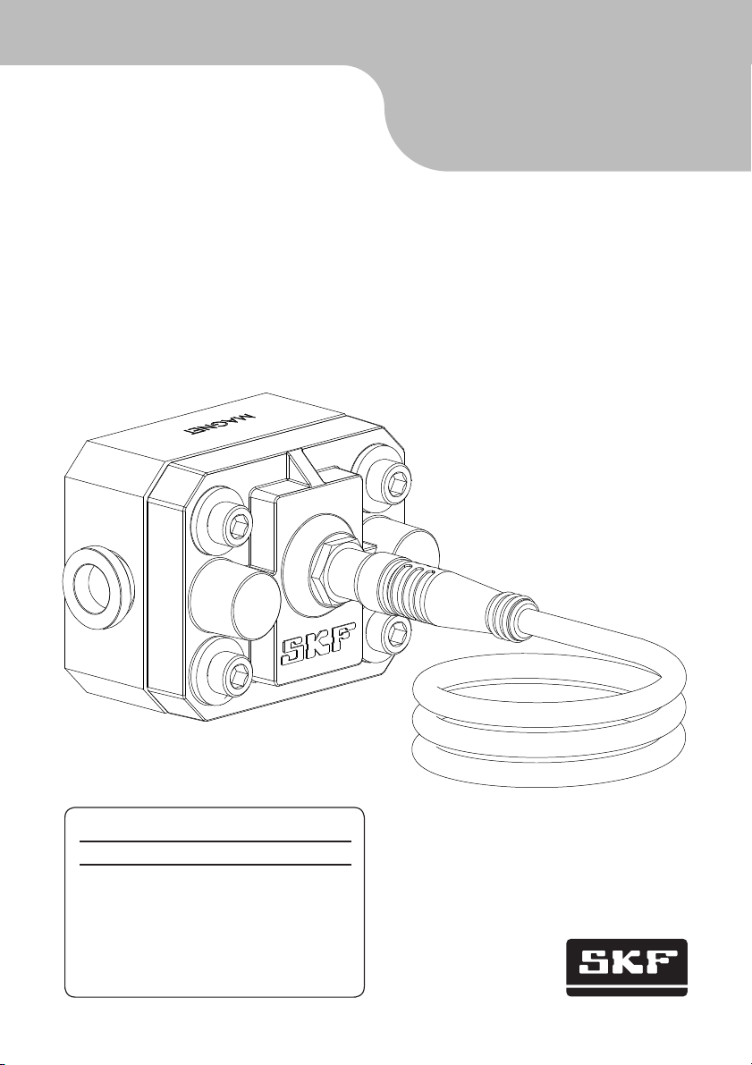
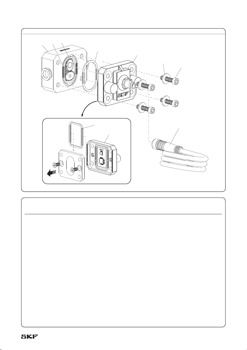
Introduction
Model 800030 a positive displacement flow
detector consisting of oval gears. One gear has
a built-in diametric magnet. As the magnet
turns with the gear, a rotating motion of
magnetic flux results.
As the magnet rotates, a hall sensor detects
the magnet flux motion. This motion is
processed by an encoder creating and sending
a digital signal to an outside controller.
A blinking LED indicates processed signals.
Specifications
Media Grease grade 0 to 2
Grease ports 1/8 in. NPT F
Wetted parts Aluminum, steel, nitrile, rubber and nylon
Maximum pressure 3,000 psi (206 bar)
Maximum operation temperature 140 °F (60 °C)
Minimum operation temperature –30 °F (–34 °C)
Sensitivity1) 0 – 140 °F –17 – 60 °C ) 0.002 – 0.5 in3(32 – 8 195 mm3) per signal generated
–30 – 0 °F (–34 – 17 °C ) 0.005 – 0.5 in3(81,9 – 8 193 mm3) per signal
Maximum altitude 10,000 ft. *3 048 m)
Maxiumum humidity 100%
Dimensions 2 x 1.6 x 1.9 in. (51 x 42 x 48 mm)
Protection IP67
Weight 0.35 lbs. (0.159 kg)
Supply voltage 12 to 30 V DC
Polarity protection 12 to 30 V DC
Nominal supply current 5 mA
Maximum supply current 35 mA
Output signal 12 to 30 V DC
Maximum output signal 30 mA
1) Entrapped air may compromise minimum sensi t ivi t y level.
3