SKY-HERO Little Spyder User manual

LITTLE SPYDER
Manuel d'utilisation
Instruction Manual
LITTLE SPYDER

2
TABLE OF CONTENTS
Introduction.•
SafetyAdvice•
GeneralInstructionsandguidelinesforuse•
Partschecklist•
Identifyingthescrews,bolts&washers•
Toolsrequiredforassembly•
Additionalequipmentthatyouwillneed(toyaircraft)•
Planningyourinstallation•
AssemblingtheTopFrame•
Installingthemotors•
ConnectingtheESCstotheMotors•
Checkingthedirectionofrotationforyourmotors•
OverviewofAircraftarmsdirectionofrotation•
AssemblyofthecompletearmwithMotor&ESC•
AircraftMotorrotationandIdentication•
MountingthearmsontotheFrame•
CoGlocation&NAZAFlightControllerInstallation•
AttachingthelowerFrame•
Mountingacamerainsidethecanopy•
Attachingthelandingskidstothelowerframe•
AttachingaZenmuseGimbal•
IdentifyingthePropeller’sdirectionofrotation•
AttachingthePropadapterandpropelleronthemotor•
AttachingtheCanopy•
ChecksbeforetheFirstFlight•
OptionnalParts•
RegularMaintenance•
LimitedWarranty•
Appendix1–ESCManual•
page3
page3
page4
page5
page6
page7
page7
page7
page8
page9
page10
page10
page11
page12
page13
page14
page15
page16
page17
page18
page19
page20
page21
page22
page23
page24
page26
page27
page29

3
INTRODUCTION
CONGRATULATIONSonyourpurchaseofaSKY-HERO Little Spyder,wehopethatit
willprovideyouwithmanyyearsoffunandentertainment.
SKY-HEROproductsaredesignedanddevelopedinBelgium(Europe),butdistributedand
supportedacrosstheglobethroughanetworkofdealersandoutletsthatcanprovideassistance
andadvice.
TheSKY-HEROethosissimple;providecool,exible,highqualityaircraft,andbackallpro-
ductswithafairandreasonablesupportservice.
Our philosophy
Foldable #takeiteverywhere
HiddenElectronic #neat
Oversizedcarbonparts #don’tfearmassivepayload
Multi-sizedframes #chooseyours
Co-axialdesign #heavywindresistance
SmartLayout #easynosevisibility
Fewparts #innitepossibilities
Looksbeautiful #bereadyforEnvy!
SAFETY ADVICE
WARNING:
ThisaircraftisnotaToy!
All SKY-HERO aircraft can be considered as sophisticated leisure products, which require
handlingwithcareandcautioninordertoavoidinjurytoyourselforothers.Ensurethatyoufully
reviewalloftheinformationinthisinstructionmanualandfamiliariseyourselfwiththecharacteristics
ofthisSKY-HEROaircraftbeforeattemptingtoyit.Thisinstructionmanualhasbeendesigned
withsafetyinmindandisprovidedtohelpyouassembleyouraircraftandtoprepareitforuse.As-
semblyofthisaircraftrequiresbasicmechanicalandelectricalskillsandyingthistypeofaircraft
requiresbasiccoordinationskillsandsomepractice.

4
GENERAL INSTRUCTIONS AND GUIDELINES FOR USE
Theaircraftshouldnotbeownbychildrenanddenitelynotanyoneundertheageof14•
Failuretofollowandcomplywiththesafetyadviceandrecommendationsinthismanual,can•
resultinseriousinjurytoyou,othersorproperty.
Youshouldalwayscheckthelocallawsandregulationsofthecountrywhereyouwilloperatethe•
aircraft,toensureyouareincompliancewiththem.Inparticularyoushouldavoidanysensitive
areassuchasMilitaryestablishments,Airports,Powerstationsandpopulatedareas.
Alwayskeepanadequatesafedistancearoundtheaircraft,ensuringthatyouavoidproximityto•
buildings,peopleandanythingwhichisoutsideofyourcontrol.
Theaircraft iscontrolled by radiosignal which canbe subject tointerference outside ofyour•
control,alossofradiocontactwiththeaircraftputsitoutofyourcontrolandcouldcauseunpre-
dictableresults.
Neverytheaircraftinconnedorbuiltupareas,whereyoumightlosevisibilityoftheaircraft.•
Neverytheaircraftinbadweatherorstrongwinds,doingsocouldcauseyoutolosecontrol•
withunpredictableresults.
Neverapproachtheaircraftuntilthepropellershavestoppedturningandnevertrytotouchit•
whilstitisinight.
Keepyourbatteriesawayfromchildren,youngchildrencouldattempttoputthemintheirmouth•
withdangerousconsequences.
Donotexposetheaircrafttowater,moistureorliquids.•
Donotattempttoytheaircraftwhenbatterypowerislow(includingtransmitterbattery).•
Beforeeachight,makesurethatallpropellersaresecurelyattached,thatthereisnodamage•
totheaircraftoritselectronicsandwiring.
Alwaysdisconnectthebatterypowertotheaircraftbeforeturningoffthetransmitterandalways•
turnthetransmitteron(checkingthepositionofallcontrols)beforeconnectingthebattery
AlwaysfollowingtheinstructionsprovidedwithyourFlightControllerandanyaccessoryequip-•
mentsuchastransmitter,batterychargersetc.

5
PARTS CHECKLIST
N° DESCRIPTION PART NUMBER
1 BUTTONHEADPLASTICSCREWM3X10MM SKH07-110
2 MAINFRAMELITTLESPYDERUP SKH03-005-U
3 HALFFRAMESPACER SKH01-102
4 STANDOFFLITTLE SKH07-110
5 BUTTONHEADSCREWM3X6MM SKH07-110
6 FRAMESPACERBLACK SKH01-002-BK
7 MOTOR(SKYHEROX2806950KV*)SKH04-007(*)
8 MOTORFRAMEBLACK SKH01-005-BK
9 WASHERM3 SKH07-110
10 ESC(20AMP4SSimonKOpto*)SKH04-008(*)
11 TUBEFRONTLITTLESPYDER SKH03-064
12 TUBEREARLITTLESPYDER SKH03-064
13 INSERTARM30MM SKH01-004
14 SOCKETHEADSCREWM3X10MM SKH07-110
15 HEXNUTNYLSTOPM3 SKH07-110
16 BUTTONHEADSCREWM4X50MM SKH07-110
17 BUTTONHEADSCREWM4X40MM SKH07-110
18 KNURLBUTTONLONGM4 SKH07-110
19 HEXNUTNYLSTOPM4 SKH07-110
20 WASHERM4 SKH07-110
21 MAINFRAMELITTLESPYDERDOWN SKH03-005-D
22 ZENMUSESPACER SKH07-110
23 LANDINGSUPPORTLEFT SKH01-101
24 LANDINGSUPPORTRIGHT SKH01-101
25 PROPNUT SKH04-002
26 PROPSHAFTWASHER SKH04-002
27 10’’CLOCKWISEPROPELLER SKH04-005-L
28 10’’COUNTERCLOCKWISEPROPELLER SKH04-005-L
29 SOCKETHEADSCREWM3X8MM SKH04-002
30 PROPSHAFTAXIS SKH04-002
31 DAMPER SKH07-110
32 CAMPLATELITTLESPYDER SKH03-006
33 CANOPYLITTLESPYDER SKH05-044
34 CLIPS SKH07-110
35 GROMET SKH07-110
36 BATTERYSTRAP SKH08-003
37 MAINLOWERFRAMEOPTIONNALLITTLESPYDER SKH08-008
38 BUTTONHEADSCREWM3X10MM SKH08-008
39 SPACERFOROPTIONNALDEVICEPLATELITTLESPYDER SKH08-008
40 DEPORTEDDEVICEMOUNTINGPLATELITTLESPYDER SKH08-008
41 ZENMUSEPLATELITTLESPYDER SKH08-008
(*) INCLUDEDINFCRVERSION
OPTIONNALPARTS
QTY
20
1
2
1
16
2
8
16
2
2
4
28
28
4
4
6
2
4
1
4
1
1
3
1
1
1
1
1
1
14
4
1
3

6
%87721+($'6&5(:0;00
:$6+(50
+(;1871<6/7230
+(;1871<6/7230
62&.(7+($'6&5(:0;00
62&.(7+($'6&5(:0;00
%87721+($'3/$67,&6&5(:0;00
%87721+($'6&5(:0;00
%87721+($'6&5(:0;0
:$6+(50
IDENTIFYING THE SCREWS, BOLTS & WASHERS

7
TOOLS REQUIRED FOR ASSEMBLY
2mmhexwrench•
2.5mmhexwrench•
3mmhexwrench•
7mmwrench•
Areamertool(optional)•
Double-sidedadhesivetape•
Bluethreadlock(Loctite)•
12mmHeatShrinktubing•
ADDITIONAL EQUIPMENT THAT YOU WILL NEED (to y air-
craft)
RadioTransmitter(andcompatible6channelormorereceiver)•
LipoBattery3S(• Capacityof3000mAHorhigherrecommended)
PLANNING YOUR INSTALLATION
BeforestartingtoassembleyourSKY-HEROaircraft,itisimportanttoplanyourbuild.You
shouldcheckthatyouhaveallofthepartsandcomponentsthatyouwillneed.Youshouldalsothink
aboutwhataccessoriesyoumightwanttoaddtotheaircraftandalsowhereontheframeyouwill
locatethem.ForexampleyoumightwanttoaddaCameraGimbalornavigationlights.Youneed
toconsiderhowanyaccessoriesthatyoumightadd,couldaffecttheCentreofGravityaswellas
thingslikewhichroutethewiringwilltake.Somewiresmightneedtobeshortenedwhilstothersmi-
ghtneedtobeextended.Onetipis(priortostartingtheassembly)layoutyourelectronics,motors,
wiring,etcagainsttheframeandcheckthatthereisspaceforeverything.
IfyouwilllocatetheESCsinthearmsoftheAircraftasrecommended,itmaybenecessarytoad-
justthelengthoftheircablestoavoidexcessivecablinginthemainbodyorthetubesoftheframe.
Rememberthatifyouwillfoldthearmsawayafterying,youmayneedsomeextracabletoallow
forthebendingofthearms.
ThesetupoftheNAZAightcontrollerisnotcoveredwithinthismanualasfullinstructionscanbe
found on the DJI website (www.dji.com) under NAZA-M (http://www.dji.com/product/naza-m-v2).
Youshouldmakesureyouhaveaccesstothemanualandnecessarysoftware,inordertocongure
theightcontrollerandtocarryoutyourpre-ightchecks.

8
ASSEMBLING THE TOP FRAME
Securethereinforcementsofframeattheupperframe(2)usingtheM3x10mmPanHead•
screws(1).
Alsoattachthecanopybracket(4)usingM3x6mmbuttonheadscrews(5).Useasmalldrop•
ofBluethread-lock(Loctite).
Note: Do not over tighten the screws in the plastic.
1
2
3
4
5
6

9
INSTALLING THE MOTORS
Orientatethemotorinthemotormount,sothattheleadscanpassthroughtheholetothetube.
Checkthatwhenthemotorisinit’scorrectposition,itwillbeabletoturnfreely,andthatifthereisa
cliponbaseofthemotor,thatitisnotrubbingagainsttheholeinthemiddleofthemotormount.
Mounttheengines(7)ontheirsupports(8)withthe3x6mmbuttonheadscrews(5)andwashers
(9).IdentifywhichholeswillbeusedtosecurethemotorandapplyasmallamountofblueThread
locktoeachholeinthebottomofthemotor.
MakesurethatthereisnoexcessThreadlockthatmightmakecontactwiththeplasticpartsasthis
couldcausetheplasticpartsoftheframetoweakenandbreak–withdangerousconsequencesif
theaircraftisinight.
Note:Formoreinformationon mountingmotors, youcan visitthe SKY-HEROchannel on
YouTubeandwatchthevideo:
“SkyHeroHowtoMountYourMotors”:https://www.youtube.com/watch?v=1-xQFuDLJi0
7
8
9
5
10
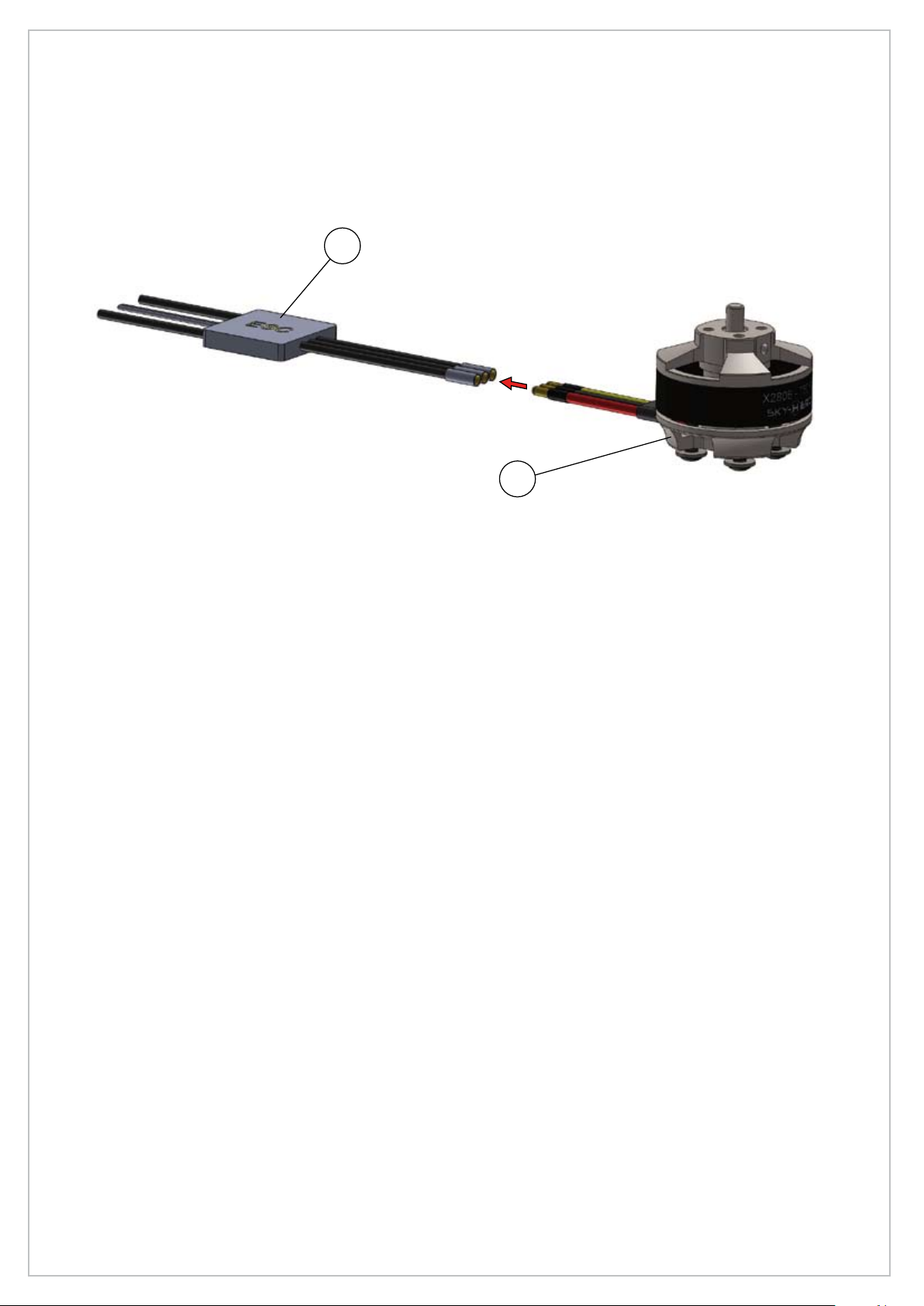
Connect motor to ESC
10
7
CONNECTING THE ESCs TO THE MOTORS
Connect one ESC to each motor. Initially it does not matter which of the 3 ESC cables you
connecttothe3cablesfromyourmotor.Itisbesthowever,toconnect3ESCcablesfor3motors
onewayandtheother3ESCcablestotheirmotors,adifferentway.
CHECKING THE DIRECTION OF ROTATION FOR YOUR MOTORS
Please refer to Image on next page.
BindyourReceivertoyourTransmitter(inaccordancewiththeTransmitterorReceiverinstruction
manual).
Ensurethatnoneofyourmotorshavetheirpropellersattached,andconnecteachmotortoeachof
yourESCs(10).
Placeamotormount(8)withit’senginesecurelymountedinside(butwithoutthe2ndhalfofthe
motormountattached),inasecurepositionwhereitwillnotinjureanyoneoryourpropertywhenit
startsup.MakesureyourTransmitterisswitchedoff.
TakingoneESC&Motorcombinationatatime,connecttheESCsignalcabletothethrottlechannel
ofyourreceiver,ensurethatyourTransmitterThrottlecontrolisatthelowestpositionandTurnon
yourTransmitter.
Connectyourreceivertosuitablepowersource(typically6v,butcheckyourreceivermanualtobe
sure),connectyourESCpowercablestoa3sor4sLipobattery.
Ifyou havenotalready doneso,you shouldcalibrateyour ESCtoyour transmitter(referto the
manualofyourESCforthemethodtofollow)IfyouareusingaSKY-HEROsuppliedESC,see
Appendix1inthismanualfortheESCinstructions.
Consideringthepositionwherethemotorarmwillbelocatedontheaircraftframe,applyasmall
amountofthrottleandcheckthatmotor’sdirectionofrotationiscorrectinrelationtothediagramin
thesection«AircraftMotorrotationandIdentication».
Ifthemotoristurninginthewrongdirection,youcanreverseit’sdirectionofrotationbyswopping
overany2(ofthe3wires)thatgobetweentheESCandtheMotor.
11
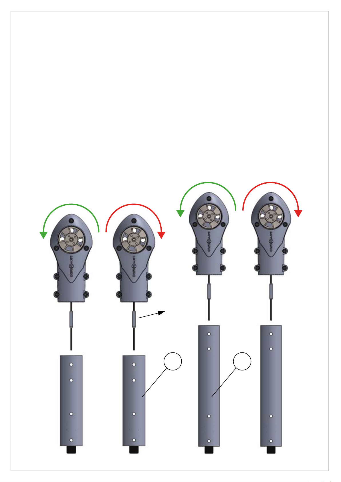
OVERVIEW OF AIRCRAFT ARMS DIRECTION OF ROTATION
2ofyour4motorsmustrotateinaclockwisedirection(CW)andtheother2inananti-clockwise
direction(CCW).
Theaircrafthas2pairsofdifferentsizedarms(2armsofthesamesizeequalsonepair).Withina
pair,onearmmustbesetupwith1motorturningclockwiseand1withamotorturninganti-clockwise
(seethesection“OverviewofAircraftarmsdirectionofrotation”).
Note:WhileyouarestillassemblingyourAircraft,itisagoodideatoplaceasmallerlabelorsticker,
onthemotormount(8)-indicatingthedirection.Itisalsoworthwhileindicatingamotornumber
(between1-4)onthesamelabel.AttachingasimilarlabeltotheESCsignalcablewiththesame
number(between1-4)willmakethingseasierwhenyoucometoconnectthemotorstoyourFlight
Controller.
Further help can be found by watching the Video «SKY-HERO HOW TO ASSEMBLE
YOUR MOTOR MOUNTS» on the Sky-HERO YouTube channel: https://www.youtube.com/
watch?v=bvkSoewk7Mw
ESC
11 12
CWCCW

12
13
14
15
8
10
ASSEMBLY OF THE COMPLETE ARM WITH MOTOR & ESC
Thecarbontube(PartNo.11/12)has2pairsofholes.Onepairhasasmallergapbetweenthem;
thisendofthetubeshouldbexedinthemotormount.
Ontheinsideofeachmotormount(8)therearetwosmallstuds,thesemustbeorientatedtocoin-
cidewiththeholesthatareinthecarbonarms.
Fixthemotormountsontheirrespectivearmsusing3X10mm(14)Socketheadscrewsandnuts
M3(15).Slidethearminserts(9)intoeachtube.
YoushouldensurethattheESCpowerleadsexitthetubefromtheouteredgeofthetube,across
theInsert(13),andintothecenteroftheaircraft.
Donotovertightenthe4screwsthatsecurethemotormounttothecarbontube.Asmallspacemust
bevisiblebetweenthetwomotormountshalves
Makesurethatthese3nutsM3(15)areorientatedcor-
rectlytotinsidetheholeandensurethattheyarefully
inserted into the motor mount hole. If the nuts are not
fullyinserted,thescrewwillnotconnectandthetwomo-
tormounthalveswillnotbesecurelyconnected

13
CW
CW
CCW
CCW
AIRCRAFT MOTOR ROTATION AND IDENTIFICATION
14
B
A
18
17
16
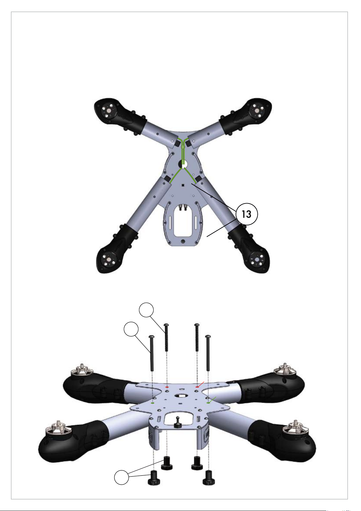
MOUNTING THE ARMS ONTO THE FRAME
Returningtotheupperchassisthatyoupartlyassembledinthesection«AssemblingtheTopFra-
me»,attachallarmsinaccordancewiththedirectionofrotationofthemotorsdisplayedonthedia-
graminsection«Aircraft Motor rotation and Identication»
Ensurethatallcablesexittheircarbontubes,passingacrossthearminsert(13)andintothecenter
oftheaircraft(seediagrambelow).
Donotforgettoleaveenoughloosecabletoallowthearmstobefoldedback
WIRES POSITION
Donotattachedtheknurlednuts(18),untilyouhaveattachedthelowerframe(seenextpage)

15
IfyouareusingtheNAZAFlightControllerwithGPS,thediagrambelowprovidessomeguidance
onwheretolocatethestandardcomponents
CoG LOCATION & NAZA FLIGHT CONTROLLER INSTALLATION
A
A
Canopy and tubes straps
2XT60 connectors :
1st to batery
2nd to PMU or Ubec
COUPE A-A
ECHELLE
1 : 1
LED
= Center position for Zenmuse H3 3D
= Forward position for Zenmuse H3 3D

16
ATTACHING THE LOWER FRAME
21
1
fyouwanttoinstallsomeelectronicsbetweentheupperandlowerframe,youshouldinstallthem
now,butkeepinminditcouldbedifculttogetaccesslaterwithoutremovingtheupperorlower
frame
Donotforgettoattachtheknurlednuts(18)asshownonthepage14.
17
20
18
19
16
17
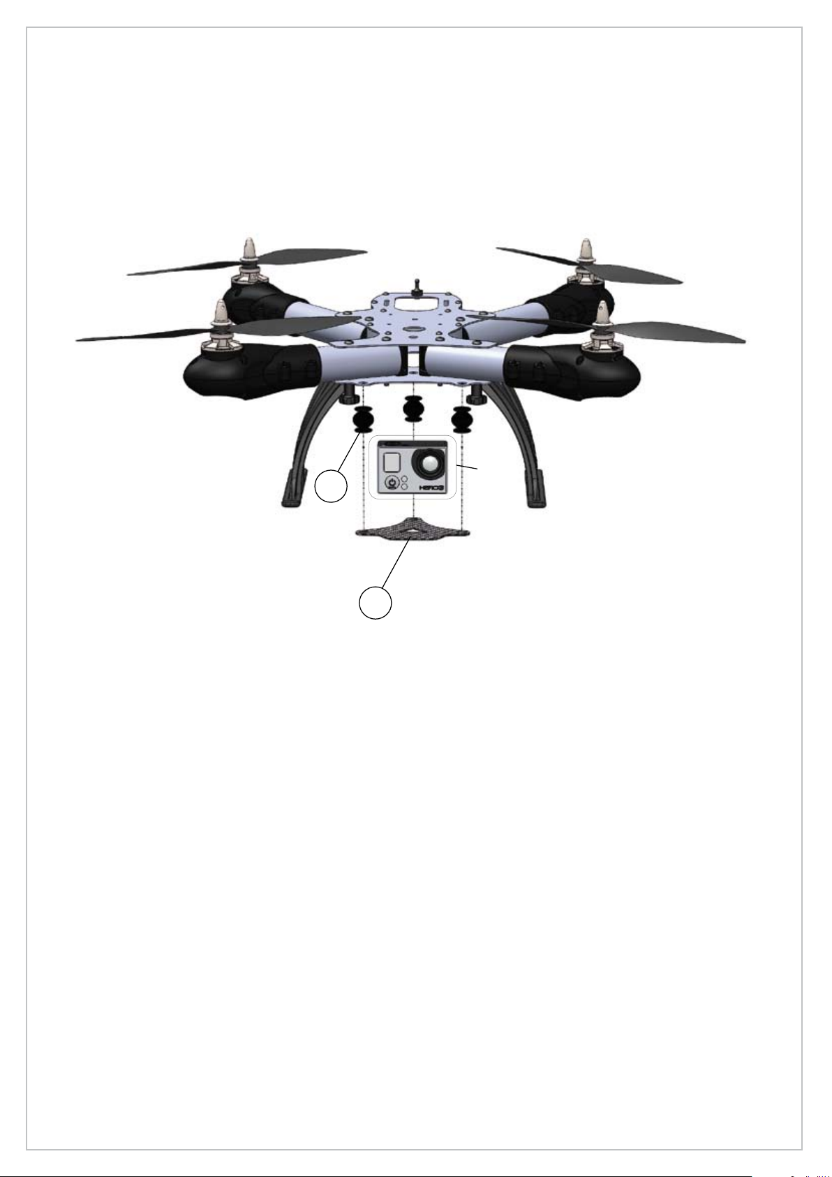
Note:ifyouareplanningtomountacamerabehindthecanopy,youwillneedtoattachitsecurelyto
theprovidedmountandalsodrillorcutaholeinthecanopy,alignedwiththelensposition.
Youmustensurethatyousecurelyattachyourcameratothemount.
FortheCameraPlate:rstinsertthe3dampersinthelowerframeandtheninserttheotherendof
thedampenersintothecarboncameraplate(32)
MOUNTING A CAMERA INSIDE THE CANOPY
32
YOUR
CAM
31
18
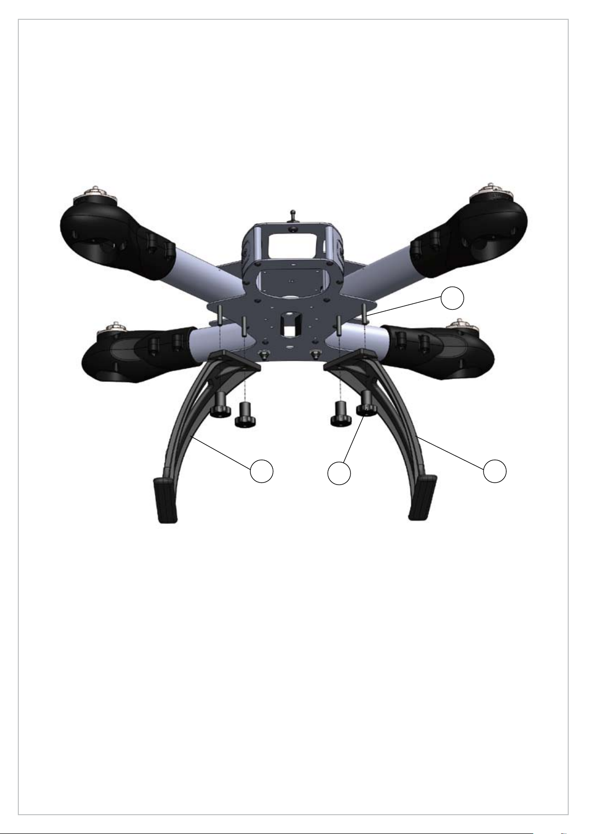
ATTACHING THE LANDING SKIDS TO THE LOWER FRAME
IfyouplantouseaCameraorinstallaGimbal,belowtheaircraft,youwillneedtoinstallthelanding
skids.
Otherwiseifyoupreferasleekerlook,youcanleavethelandingskidsoff.
Securethelandingskidsusing4xButtonHeadScrewsM4x12MMand4xKnurlButtonLong
M4.
23 24
18
16
19
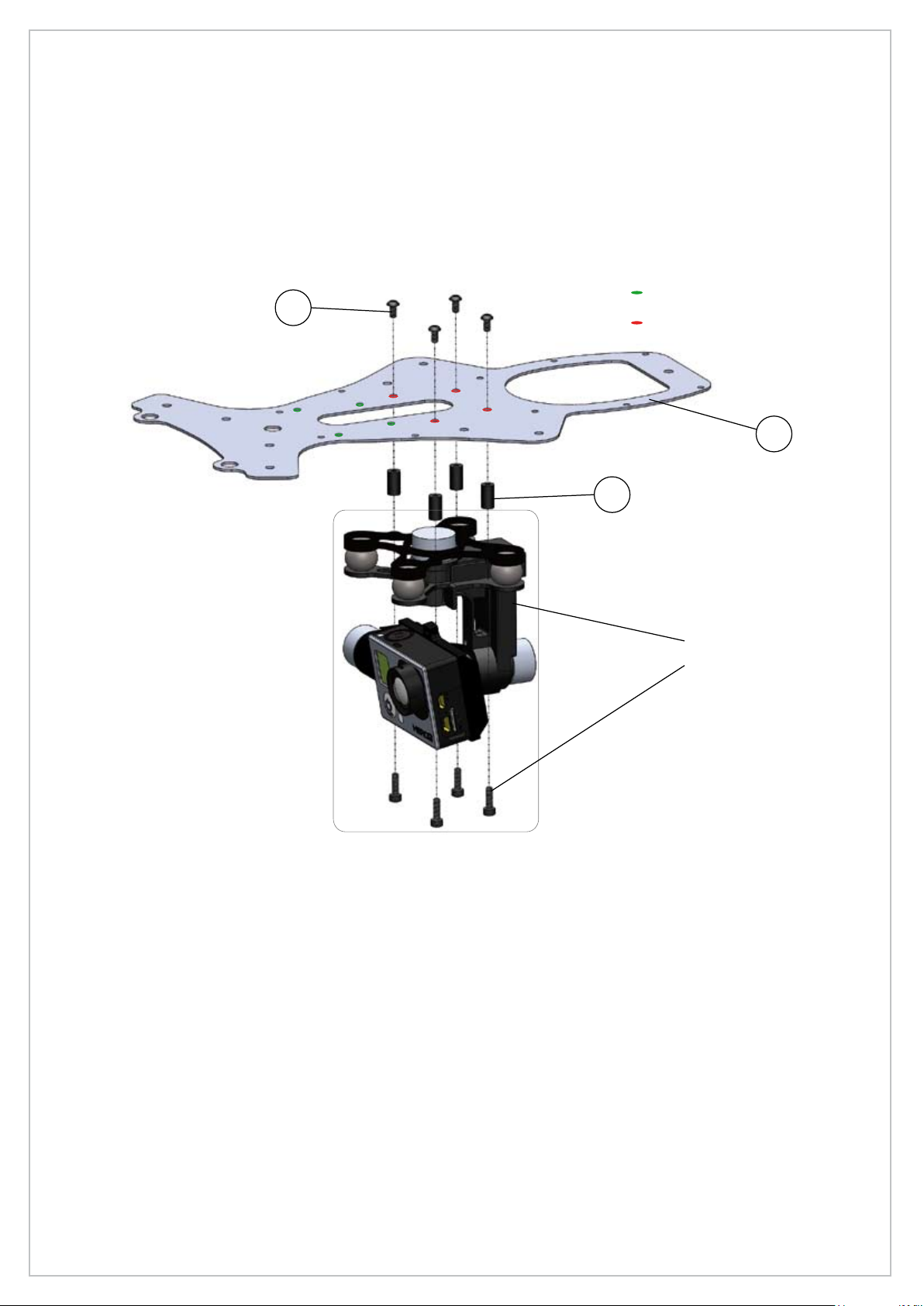
ATTACHING A ZENMUSE GIMBAL
IfyouinstalloraregoingtoinstallaDJIZENMUSEH33DGimbal,nowinstallthespacers(22)un-
derthelowerframe(21)withthe3x5mmbuttonheadscrews(5).
Youhavethechoicebetweenacenteredorforwardposition.
Donotforgettousesomethreadlockasthescrewswillbehardtoreachaftertheframeisassem-
bled
22
ZENMUSE H3-3D
WITH ZENMUSEʼS
PROVIDED SCREWS
21
5
Forward position for Zenmuse
Centered position for Zenmuse
20
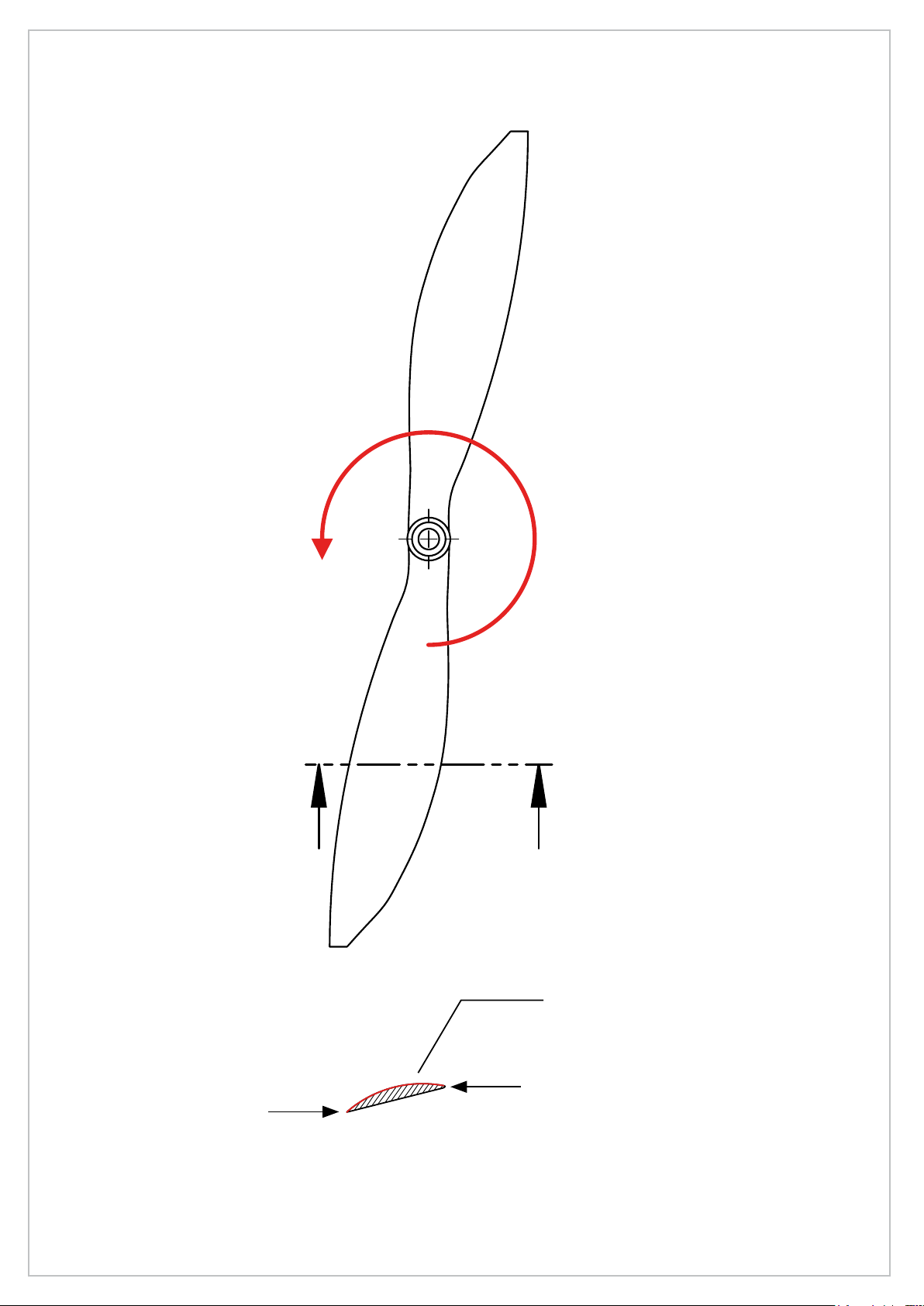
IDENTIFYING THE PROPELLER’S DIRECTION OF ROTATION
$
$
&283(
$$
(&+(//(
Always place the convex side of
the propeller to the top
Leading edge (front of the propeller)
Trailing edge
(back of the propeller)
Other manuals for Little Spyder
1
Table of contents
Other SKY-HERO Drone manuals

SKY-HERO
SKY-HERO Anakin Club Racer User manual

SKY-HERO
SKY-HERO Spy SKH00-301 User manual

SKY-HERO
SKY-HERO Little Six User manual

SKY-HERO
SKY-HERO Anakin Installation guide

SKY-HERO
SKY-HERO Loki MK2 User manual

SKY-HERO
SKY-HERO ANAKIN NATURAL BORN RACER User manual

SKY-HERO
SKY-HERO Loki MK2 User manual

SKY-HERO
SKY-HERO Loki MK2 User manual


