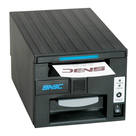
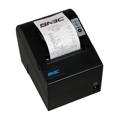
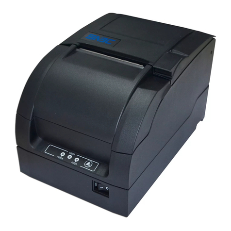
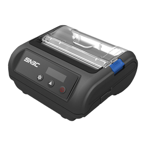
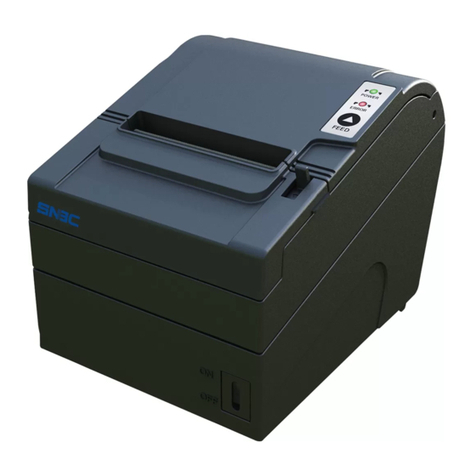
SNBC BTP-2002NP User manual

CONFIDENTIAL
SERVICE MANUAL
Receipt Printer
BTP-2002NP
Shandong New Beiyang Information Technology Co., Ltd.

Confidential BTP-2002NP Service Manual
- 1 -
Revision Sheet
Date Version No. Description Distributor
2006-10-18 V1.0 Release
Mr. Peng Yuan Bin
Mr. Yang Min
Mr. Xu Jia Bo
Mr. Zhang Tao
2007-04-25 V2.0 Revision V2.0 Mr. Yang Min
2007-06-30 V2.01 Revision V2.01 Mr. Yang Min
2007-12-05 V2.02 Add watermark command Mr. Yang Min
2008-6-13 V2.03
Change speed from 150mm/s to
200mm/s
Mr. Xu Jia Bo

Confidential BTP-2002NP Service Manual
Declaration
Information in this document is subject to change without notice. SHANDONG NEW BEIYANG
INFORMATION TECHNOLOGY CO., LTD. (hereinafter referred to as “SNBC”) reserves the right to
improve products as new technology, components, software, and firmware become available. If users need
further data about this product or have any doubt about safety issues that might arise from using it, please
feel free to contact SNBC or your local agents.
No part of this document may be reproduced or transmitted in any form or by any means, electronic or
mechanical, for any purpose without the express written permission of SNBC.
Copyright
Copyright © 2008-2009 by SNBC
Printed in China
Version 2.03
Trademarks
SNBC registered trademarks:
Warning and Caution
Warning: Items shall be strictly followed to avoid damages to body and equipment.
Caution: Items with important information and prompts for operating the printer.
The quality control system of SNBC has been approved of the following certification.
- 2 -
(DNV)ISO9001:2000
The environmental control system of SNBC has been approved of the following certification.
(DNV)ISO14001:2004

Confidential BTP-2002NP Service Manual
BTP-2002NP has been approved of the following certification.
Contact us
Address: No.169 Huoju Rd, Weihai, Shandong, China. 264209
Hot line: +86-631-5673777
Fax: +86-631-5673778
E-mail: [email protected]
- 3 -

Confidential BTP-2002NP Service Manual
- 4 -
Notes
1) Follow the steps in this manual hereafter during maintenance.
2) Make sure that the printer and the computer are turned off before pluging the communication cable,
changing print head or doing maintenance to the printer.
3) Be sure to protect it against electrostatic damage when maintaining print head and other electronics.
4) Time between turning on and turning off the printer is no less than 20 seconds.
5) Do not operate the printer when paper is end. Doing so can damage print head.

Confidential BTP-2002NP Service Manual
- 5 -
Contents
1 FEATURES AND SPECIFICATIONS ................................................................................ 1
1.1 FEATURES ............................................................................................................................................................1
1.2 SPECIFICATIONS ..................................................................................................................................................1
2 PRINTER OVERVIEW....................................................................................................... 2
3 MAIN CONTROL BOARD UNIT BLOCK DIAGRAM ......................................................... 3
4 DISASSEMBLY AND ASSEMBLY ..................................................................................... 5
4.1 MAINTENANCE TOOLS .........................................................................................................................................5
4.2 DISASSEMBLE THE PRINTER................................................................................................................................6
4.2.1 Remove the Main Control Board .................................................................................................................... 6
4.2.2 Disassemble the Main Control Board and the Interface Board.................................................................. 7
4.2.3 Disassemble Printer Top Cover and Cutter Cover ...................................................................................... 8
4.2.4 Disassemble Cutter Cover .............................................................................................................................. 8
4.2.5 Disassemble the Top Housing and the Feed button/ LED Module ........................................................... 9
4.2.6 Disassemble the Printer Mechanism ............................................................................................................. 9
4.2.7 Disassemble the Platen Roller...................................................................................................................... 10
4.2.8 Disassemble the Cutter Module ................................................................................................................... 10
4.2.9 Disassemble the Motor .................................................................................................................................. 11
4.2.10 Disassemble the Micro Switch.................................................................................................................... 11
4.2.11 Disassemble the Print head Module and Spring Pressing Plate........................................................... 12
4.2.12 Disassemble the Print head........................................................................................................................ 12
4.2.13 Disassemble the Paper Near End Sensor ................................................................................................ 13
4.2.14 Disassemble the Power Switch .................................................................................................................. 13
4.2.15 Disassemble the Paper End Sensor Module............................................................................................ 14
4.3 ASSEMBLY ..........................................................................................................................................................14
5 ERROR TYPES AND PROCESSING ............................................................................. 15
6 TROUBLESHOOTING GUIDE........................................................................................ 16
6.1 POWER SUPPLY .................................................................................................................................................16
6.2 PRINTING............................................................................................................................................................16
6.3 PAPER FEEDING.................................................................................................................................................17

Confidential BTP-2002NP Service Manual
- 6 -
6.4 AUTO CUTTER....................................................................................................................................................17
6.5 CASH DRAWER...................................................................................................................................................17
6.6 SENSORS............................................................................................................................................................18
6.7 LED/KEY AND BUZZER .....................................................................................................................................18
APPENDIX ......................................................................................................................... 19
APPENDIX A: MAIN CONTROLL BOARD DESCRIPTION............................................................................................19
APPENDIX B: HEXADECIMAL DUMP .........................................................................................................................27
APPENDIX C: CONTROL SEQUENCES......................................................................................................................28
APPENDIX D: EEPROM SETTING TABLE................................................................................................................30
APPENDIX E: SERVICE PARTS LIST .........................................................................................................................31
APPENDIX F: PRINTER EXPLODED VIEW .................................................................................................................35
APPENDIX G: OUTLINE DRAWING............................................................................................................................36

Confidential BTP-2002NP Service Manual
1 Features and Specifications
1.1 Features
The BTP-2002NP is a high performance thermal printer. It can be widely used for real-time printing
applications, such as for POS systems, hospitality, ATM, etc.
¾Low noise and high printing speed.
¾Easy paper loading: drop in and print.
¾Easy operation and maintenance.
¾Continuous paper can be used with different paper width.
¾Auto cutter (full cut or partial cut).
¾Cash drawer control connector.
¾Optional communication interfaces (daughter boards) .
¾Optional wall mount parts and spill proof cover.
1.2 Specifications
Print Speed Max. 200mm/s
Resident Character Sets PC437, PC850, PC860, PC863, PC865, PC852, PC858, WPC1252,
C866, Katakana
Integrated Bar Codes Code 39, UPC-A, UPC-E, EAN-8, EAN-13, Codabar, Code 128
Printer Resolution 203dpi x 180dpi (dots/inch)
Print Width 80mm, 640 Dot Positions (Max.)
Flash Memory (Total) 1MB
Flash Memory (Font/Logo) 128KB
AutoCutter FullCutorPartialCut
Interfaces RS232, Parallel, USB, Ethernet or WLAN
Cash Drawer Drive 1 or 2 Cash Drawers
Sensors Top Cover Open, Paper End, Paper Near End
Paper Roll Width Optional 82.5mm/80mm/76mm/69.5mm57.5mm
Max Paper Roll Diameter 83mm
Wall Mount Optional-Wall Mount Kit
Note:
The size of Flash Memory is different depending on different models.
- 1 -

Confidential BTP-2002NP Service Manual
- 2 -
2 Printer Overview
This printer is made up of the following major components:
¾BTP-2002NP Printer Mechanism (Sensor and LED/KEY switch circuit board assembly)
¾Interface board assembly
¾Main Control board

Confidential BTP-2002NP Service Manual
3 Main Control Board Unit Block Diagram
The block diagram of various components and main control board is shown below.
Block diagram
The top side of main control board
- 3 -

Confidential BTP-2002NP Service Manual
The bottom side of main control board
Position of each connector
- 4 -

Confidential BTP-2002NP Service Manual
- 5 -
4 Disassembly and Assembly
Cautions:
Do not disassemble, assemble or adjust the printer if it works properly. Do not loosen any screw
unless necessary.
When disassembling and assembling, avoid all wires and cables form damages. Do not let them
pass by a narrow space or place them in improper position.
When handling the thermal print head or electronic component, make sure to take some
measures to protect it against electrostatic charge.
During maintenance, be careful not to leave parts or screws unfixed inside the printer.
4.1 Maintenance Tools
¾Screw Driver (Philips type)
¾Screw Driver (line type)
¾Wire clamp pliers

Confidential BTP-2002NP Service Manual
4.2 Disassemble the Printer
Disassembly steps are shown as below:
4.2.1 Remove the Main Control Board
Pictures Instructions
1
Top view of printer.
2
Remove the two screws.
3
Pull out the main control board module slantways
for a certain distance in the direction.
4
Detach the connectors and take out the main
control board module.
5
Picture of the main control board module.
- 6 -

Confidential BTP-2002NP Service Manual
4.2.2 Disassemble the Main Control Board and the Interface Board
Pictures Instructions
1
Remove the two screws of the interface metal plate.
2
Pull out the interface board.
3
Remove the four screws on the control board
(M3x4) and take out the main control board.
4
Picture of the main control board.
- 7 -

Confidential BTP-2002NP Service Manual
4.2.3 Disassemble Printer Top Cover and Cutter Cover
Pictures Instructions
1
Remove the two screws.
2
Remove the printer top cover.
3
Picture of the opened top part of the mechanism.
4.2.4 Disassemble Cutter Cover
Pictures Instructions
1
Hold the cutter cover at the position as shown.
2
Pull the cutter cover in the direction as shown and
take it out.
- 8 -

Confidential BTP-2002NP Service Manual
4.2.5 Disassemble the Top Housing and the Feed button/ LED Module
Pictures Instructions
1
Remove the two screws.
2
Take off the upper cover in the direction as shown.
3
Remove the two screws.
4
Picture of Feed button/ LED Module
4.2.6 Disassemble the Printer Mechanism
Pictures Instructions
1
Remove the four screws.
2
Take out the printer mechanism.
- 9 -

Confidential BTP-2002NP Service Manual
4.2.7 Disassemble the Platen Roller
Pictures Instructions
1
Remove the platen gear.
2
1. Remove the e-ring with screw driver (line type).
2. Remove the platen bushing.
3
1. Remove the e-ring with screw driver (line type).
2. Remove the platen bushing.
3. Take off the platen roller.
4.2.8 Disassemble the Cutter Module
Pictures Instructions
1
Cut off the clip with wire clamp pliers.
2
Remove the two screws.
3
Pull out the cutter unit for a certain distance in the
direction as shown and take it off.
- 10 -

Confidential BTP-2002NP Service Manual
4.2.9 Disassemble the Motor
Pictures Instructions
1
Cut off the clip with wire clamp pliers.
2
Remove the two screws.
3
Take off the motor.
4.2.10 Disassemble the Micro Switch
Pictures Instructions
1
Remove the two screws.
2
Take off the Micro-switch.
- 11 -

Confidential BTP-2002NP Service Manual
4.2.11 Disassemble the Print head Module and Spring Pressing Plate
Pictures Instructions
1
Push the spring pressing plate along the indication
of the arrow.
2
Remove the spring pressing plate and the springs.
3
Take off the print head module.
4.2.12 Disassemble the Print head
Pictures Instructions
1
Remove the two screws.
2
Detach the print head, print head protection plate 1
and 2.
- 12 -

Confidential BTP-2002NP Service Manual
4.2.13 Disassemble the Paper Near End Sensor
Pictures Instructions
1
Remove the four screws.
2
Take off the paper near-end sensor modules.
4.2.14 Disassemble the Power Switch
Pictures Instructions
1
Cut off the clip with wire clamp pliers.
2
Remove the glue with a screw driver (line type).
3
Clamp the stretch slices.
4
Pull out the power switch.
- 13 -
Other manuals for BTP-2002NP
2
Table of contents
Other SNBC Printer manuals

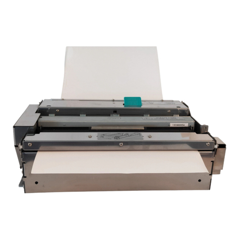
SNBC
SNBC BTP-R180II Owner's manual
SNBC
SNBC KIOSK Series User manual
SNBC
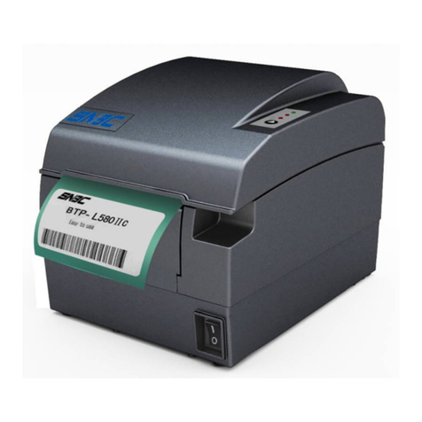
SNBC BTP-L580IIC User manual
SNBC
SNBC BT-UC056III User manual
SNBC
SNBC BT-T080 Owner's manual
SNBC
SNBC BTP-R880NP Owner's manual

SNBC
SNBC BTP-M300 Owner's manual
SNBC
SNBC BT-T080R User manual

SNBC
SNBC BTP-M280 User manual

SNBC
SNBC BTP-R880NP User manual
