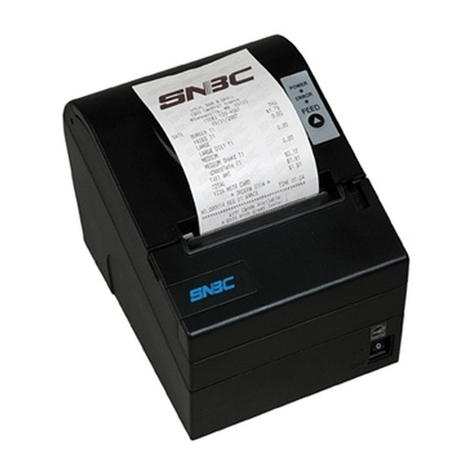
SNBC BTP-R681 User manual

USER’S MANUAL
Thermal Receipt Printer
BTP-R681
Shandong New Beiyang Information Technology Co. Ltd.

BTP-R681 User’s Manual
- 1 -
Declaration
Information in this ocument can not be change without notice. SHANDONG NEW BEIYANG
INFORMATION TECHNOLOGY CO., LTD. (hereinafter referre to as “SNBC”) reserves the right
to improve pro ucts as new technology, components, software, an firmware become available. If
users nee further ata about this pro uct, please feel free to contact SNBC or your local ealer.
No part of this ocument may be repro uce or transmitte in any form by any means, electronic
or mechanical, for any purpose without the express written permission of SNBC.
Copyright
Copyright © 2015 by SNBC
Printe in China
Version 1.0
Trademark
Registere tra emark
Warning and Caution
Warning: Items shall be strictly followe to avoi injury or amage to bo y an evices.
Caution: Items with important information an prompts for operating the printer.
SNBC has passed the following certifications:
ISO9001 Quality Control System Certification
ISO14001 Environmental Management System Certification
OHSAS18001 Occupational Health an Safety Management System Certification
IECQ QC 080000 Hazar ous Substance Process Management System Certification
Contact us:
A ress: No.169 huoju roa , high-tech zone, Weihai, China
Hot line: 400-618-1368 800-860-1368
Fax: +86-631-5656098
PC: 264209
Website: www.newbeiyang.com.cn

BTP-R681 User’s Manual
- 2 -
General Safety Information
Before installing an using the printer, please rea the following items carefully.
1. Safety instructions
Warning: Do not touch the cutter of the printer.
Warning: The print hea is a thermal element an it is at a high temperature uring printing or
just after operation, therefore o not touch it or its peripherals for reasons of safety.
Warning: The print hea is an ESD-sensitive evice. To avoi amage, o not touch either its
printing parts or connecting parts.
2. Caution
1) Install the printer on a flat an stable place.
2) Reserve a equate space aroun the printer so that convenient operation an maintenance can
be performe .
3) Keep the printer away from water source, an avoi irect exposure to sun light, strong light
an heat of fire.
4) Do not use or store the printer in a place expose to high temperature, moisture an serious
pollution.
5) Do not place the printer on a place expose to vibration or impact.
6) No ew con ensation is allowe to the printer. In case of such con ensation, o not turn on
the power until it has completely evaporate .
7) Connect the DC a apter to an appropriate groun ing outlet. Avoi sharing a single electrical
with large power motors an other evices that may cause the fluctuation in voltage.
8) Disconnect the DC a apter when the printer is not use for a long time.
9) Do not let the water or electric materials (like metal) go into the printer. If this happens, turn off
the power imme iately.
10) Do not allow the printer to start printing when there is no recor ing paper installe ; otherwise
the print hea an platen roller will be seriously amage .
11) To ensure the print quality an normal lifetime, use recommen e or goo quality paper.
12) Shut own the printer when connecting or isconnecting interfaces connectors to avoi
amage to the control boar .
13) Set the print arkness to a lower gra e as long as the print quality is acceptable. This will help
to keep the print hea urable.
14) The printer shoul only be isassemble or repaire by a technician, who is certifie by the
manufacturer.
15) Keep this manual safe an at han for rea y reference.
Caution: The following content about cutter only applies to printers with cutter.

BTP-R681 User’s Manual
- 3 -
Contents
1
Introduction
........................................................................................................................................ - 1 -
1.1
Outline
........................................................................................................................................... -
1
-
1.2
Features
........................................................................................................................................ -
1
-
2
Specification
....................................................................................................................................... - 2 -
2.1
Technical specification
................................................................................................................ -
2
-
2.2
Cutter parameters
........................................................................................................................ -
3
-
2.3
Paper specification
...................................................................................................................... -
4
-
2.3.1
Parameters of continuous paper
........................................................................................... - 4 -
2.3.2
Parameters of marke paper
................................................................................................. - 4 -
2.3.3
Parameters of label paper
..................................................................................................... - 5 -
3
Appearance and components
......................................................................................................... - 6 -
3.1
Appearance an mo ules
........................................................................................................... -
6
-
3.2
LED an buzzer
........................................................................................................................... -
8
-
4
Installation
.......................................................................................................................................... - 9 -
4.1
Unpacking
..................................................................................................................................... -
9
-
4.2
Printer installation
........................................................................................................................ -
9
-
4.3
Power an communication interface
....................................................................................... -
11
-
4.3.1
Power connection
................................................................................................................. - 11 -
4.3.2
Interface connection
............................................................................................................. - 11 -
4.3.3
USB interface connection
.................................................................................................... - 12 -
4.3.4
Cash rawer connection
...................................................................................................... - 12 -
4.4
Paper roll installation
................................................................................................................. -
13
-
4.4.1
Paper type confirmation
....................................................................................................... - 13 -
4.4.2
Install/replace paper roll
...................................................................................................... - 13 -
4.5
Paper near en position a justment
....................................................................................... -
14
-
4.6
Power-on an self-test
.............................................................................................................. -
14
-
4.6.1
Power-on
................................................................................................................................ - 14 -
4.6.2
Print self-test page
............................................................................................................... - 14 -
4.7
Hexa ecimal umping function
................................................................................................ -
15
-

BTP-R681 User’s Manual
- 4 -
5
Routine maintenance
..................................................................................................................... - 16 -
5.1
Cleaning print hea an platen roller
...................................................................................... -
16
-
5.2
Cleaning mark sensor
............................................................................................................... -
16
-
5.3
Clearing jamme paper an cutter error
................................................................................. -
16
-
6
Interface signal
................................................................................................................................ - 17 -
6.1
Serial interface
........................................................................................................................... -
17
-
6.2
Parallel interface
........................................................................................................................ -
17
-
6.3
USB interface
............................................................................................................................. -
19
-
6.4
Ethernet interface
...................................................................................................................... -
19
-
6.5
Double communication interface
............................................................................................. -
20
-
6.6
Power interface efinition
......................................................................................................... -
21
-
6.7
Cash rawer interface signal efinition
.................................................................................. -
21
-
7
Troubleshooting
.............................................................................................................................. - 23 -
7.1
Printer oesn’t work
................................................................................................................... -
23
-
7.2
Error LED an buzzer alarm
..................................................................................................... -
23
-
7.3
Problems uring printing
........................................................................................................... -
23
-
8
Power management
........................................................................................................................ - 24 -

BTP-R681 User’s Manual
- 1 -
1 Introduction
1.1 Outline
BTP-R681 is evelope for high-en thermal receipt printing market, which is wi ely use .
BTP-R681 can be connecte with other evices via serial, USB, Ethernet an WLAN. It
provi es rivers for operation systems such as Win ows 2000 / XP /Server 2003 / Vista /
Server200 / Win7 / Win8 /Win8.1 / Server 2012, POSRea y2009 / POSRea y7, Linux, Mac an
UPOS mi leware.
Note: Win ows an Linux rivers support 64-bit operation system.
1.2 Features
Drawer-style paper cabinet, paper out from the front, an easy maintenance;
Cabin-style integrate esign, ustproof an waterproof (IP31), easy to remove the oil
contamination;
High intensity bo y an high loa capacity, can be use as a storage table;
Low noise, high printing spee ;
Support continuous paper, marke paper, an label paper;
Paper cabinet wi th is a justable, compatible with various paper wi th of 56~82.5mm;
Cutter is esigne for easy maintenance an can irectly open the paper cabinet for cutter
maintenance when the moveable bla e has not come back to its position;
Support paper saving, water mark, upsi e- own, two-color printing;
Rich interfaces: onboar USB, expan able serial / parallel / Ethernet / Bluetooth / WIFI /
serial + Ethernet interface;
Rich options: hanging bracket, LOGO plate, LED light bar, an cover plate of power switch
are optional;
Meet the requirements of Energy Star, Reach an RoHs, energy saving an environmental
protection.

BTP-R681 User’s Manual
- 2 -
2 Specification
2.1 Technical specification
Item Parameter
Printing
Print metho Direct thermal line printing
Resolution 203 × 203 DPI
Paper wi th 56~82.5mm, continuously a justable
Print wi th Max. 80mm
Print spee Continuous paper printing spee : Max.310mm/s
Label paper printing spee : Max.150mm/s
Flash LOGO Max. 512K bytes
Data buffer 64K bytes, 4K bytes or 45 bytes
Interface
USB USB2.0 (full spee )
Serial interface RS-232C
Parallel interface IEEE1284
Ethernet interface 10/100BASE-T
Cash rawer Can select to controlling 1~2 cash rawers
Memory RAM: 2MB, Flash: 4MB
Printer status etection
Paper en sensor/ black mark sensor;
Paper near en sensor;
Front cover position sensor;
Label etection sensor;
Paper presence sensor
Print hea temperature sensor;
Printer voltage etection
Ba ots etection of print hea
Cut mo e Full cut, partial cut
Barco e
1D UPC-A, UPC-E, CODE 39, CODE 93, CODE 128, EAN8, EAN13,
ITF, CODABAR
2D PDF417, QR, Maxico e
Fonts
Font A: 12 × 24
Font B: 9 × 17
Kanji font A: 24 × 24
Character set
95 Alphanumeric
14 types of international characters
128 x 68 co e page
Optional: Tra itional Chinese, Simplifie Chinese
(GB2312/18030), Japanese, Korean, English, HK
User- efine font (95) & co e page
Character enlargement All characters can be enlarge 1-6 times horizontally an vertically
Character rotation Rotation printing in four irections (0°, 90°, 180°, 270°)
Comman ESC/POS compatible

BTP-R681 User’s Manual
- 3 -
Paper
Paper type Thermal continuous paper, Thermal marke paper
Paper roll OD Max. 83mm
Paper thickness 0.06mm~0.10mm thermal paper
0.13mm-0.15mm label paper
Power
supply
Input 100-240VAC, 50-60Hz
Output 24V ± 5% DC, average current 2.5A
External or not External power a apter
Human-machine
interface
Power switch Support
Button Support
LED Support, inclu ing POWER LED, ERROR LED
Buzzer Support, 24V buzzer
Reliability
Lifetime of print hea ≥150Km (stan ar test sample with 12.5% uty ratio)
Lifetime of cutter 2,000,000 cuts (stan ar test situation)
MCBF 70,000,000 lines
MTBF 360,000 hours (main control boar )
Operation temperature an humi ity 5°C~45°C,20%~90%RH(40°C)
Storage temperature an humi ity -40°C~60°C,10%~90%RH(40°C)
Overall imensions 218mm(L)*136.6mm(W)*116.5mm(H)
Functions
Saving paper Support
Button configuration Support (configure the printer without computer)
Right-up-si e printing Support
Water mark printing Support
Gray scale printing Support
Table 2.1-1 Technical specifications
2.2 Cutter parameters
Item
Parameter Remarks
Cutting metho Sli ing bla e
Cutting time
500ms The time of one cut
Cutting interval
3s 20 cuts/minute (Max.)
Applicable paper types
0.06mm~0.10mm thermal paper
0.13mm-0.15mm label paper
Thermal paper, label paper or normal
paper of the same thickness
Operation voltage
24VDC
Max. operation current
1.2A Operation voltage 24VDC
Cutter lifetime
2,000,000 cuts (0.063mm thick
thermal paper, stan ar test
situation)
* Inclu ing full cut an partial cut
Table 2.2-1 Technical parameters of cutter
*
Full cut: Cut off the paper completely;
Partial cut: Cutting with one point in the mi le left uncut.

BTP-R681 User’s Manual
- 4 -
2.3 Paper specification
2.3.1 Parameters of continuous paper
Paper type: thermal paper
Paper supply mo e: paper roll
Paper wi th: 56-82.5mm
Paper thickness: 0.06mm-0.10mm
Thermal layer: outwar
Paper roll specification: paper roll OD Max ф83 mm, core ID Min. ф12mm
Paper recommen e :
Paper model Manufacturer
600-3.1 APPLETON Papers Inc
KLS_46_e KANZAN Spezialpapiere GmbH
FD210 OJI Paper CO., LTD.
Table 2.3-1 Recommended thermal paper model
2.3.2 Parameters of marked paper
BTP-R681 can support marke paper printing an set the cutting an initial printing position
accurately. The marke paper not only shoul meet the specifications of thermal paper roll, but
also shoul meet the following requirements:
Figure 2.3-1 Schematic drawing of marked paper specifications
L1 mark height: 3mm≤ L1≤13mm
L2 mark length: L2≥8mm
L3 istance between two marks: 30mm≤L3<450mm
Mark position: Mark etection is supporte on any position of the thermal si e, but for
non-thermal si e marke paper, only the marks on the left (paper wi th 80mm), mi le, right
(paper wi th 80mm) can be etecte .
Thermal si e mark sensor position: reserve the left, mi le an right positions
Non-thermal si e mark sensor position: the mi le, an the left/right position (optional)
Reflectivity: The reflectivity of the black mark must be no more than 15% while the reflectivity
of the paper itself shoul excee 85%. There shoul be no image between the two marks,
such as the a vertisement, etc.

BTP-R681 User’s Manual
- 5 -
2.3.3 Parameters of label paper
BTP-R681 can support label paper printing an set the cutting an initial printing position
accurately. The label paper not only shoul meet the specifications of thermal paper roll, but
also shoul meet the following requirements:
Paper type: thermal label paper
Paper supply mo e: paper roll
Base paper wi th (a): 56mm-82.5mm±0.5
Label wi th (c): 56mm-80mm±0.5
Margin wi th (b): ≤1 mm
Paper thickness: 0.13mm-0.15mm±0.005(label paper + base paper)
Label height ( ): 30mm-300mm
Label space (e): 2mm-10mm
Thermal layer: outwar
Paper roll OD (Max): ф83 mm
Light transmittance of the base paper: >60%
Light transmittance of the label an base paper: <20%
Cut position: mi le in the label space for the stan ar configuration, an the cut position is
a justable
Label positioning accuracy: ≤1mm
Caution:
Please use the recommen e paper or its equivalents. Using the paper of low quality might
affect the print quality an shorten the lifetime of print hea ;
Do not stick paper onto the core shaft;
If the paper is contaminate by chemical or oil, it may iscolor or lose heat sensitivity at the
pollute spot, which will affect the print affect;
Do not rub the paper surface with fingers or har objects, otherwise it may iscolor;
When the environment temperature goes up to 70℃, paper will iscolor. Thus on not use or
store paper un er high temperature, high humi ity an strong light con itions.
The mark is measure uring printing an paper fee ing. If the mark height value etecte
by the sensor is bigger than the efault value ( efault setting is 13mm), the printer will alarm
paper en .

BTP-R681 User’s Manual
- 6 -
3 Appearance and components
3.1 Appearance and modules
Figure 3.1-1 Schematic drawing of appearance and modules
1—Front cover 2—Spanner for opening cover 3—Power switch
4—Button label 5—LOGO plate 6—Thumb wheel for a justing paper gui e
7—Spanner for a justing paper near en sensor
8—cutter 9—Gear of platen roller
10—Platen roller 11—Label etection sensor 12—Paper en /mark sensor
13—Right paper gui e 14—Front cover status etection sensor
15—Paper cabinet
16—Left paper gui e 17—FFC cable 18—Baffle of sli ing bla e
19—LED 20—Top cover 21—Cash rawer interface
22—S terminal 23—USB interface 24—Communication interface
25—Power LED 26—Error LED 27—Fee button

BTP-R681 User’s Manual
- 7 -
Button and component function:
a Fee button (27)
Fee paper:
Printer will fee paper when the fee button is presse own un er normal con ition. To
fee continuously, keep pressing the button.
Print configuration sample:
Pressing own the fee button while turning on the power, the printer will print out the
configuration sample, which inclu es print wi th, print spee , etc.
Enter button configuration mo e:
Press own the fee button while turning on the power, the printer will print out the
configuration sample, an enter pause status (error LED flashes) after cutting paper. Keep
pressing the fee button at this time, the printer will enter button configuration mo e.
Press the button to clear the cutter error:
Press the button for a short time when a cutter error occurs, the printer will try to clear the
cutter error automatically.
b Error LED (26)
In icate printer status. Un er normal status, error LED is off. Un er error status (e.g. paper
en , etc.), error LED flashes.
c Power LED (25)
In icate printer power status (ON/OFF).
Power switch (3)
Press own “O” to power off, an press own “—”to power on.
e Front cover status etection sensor (14)
Detect the printer status (open/close ).
f Paper en /mark sensor (12)
Un er continuous paper mo e, it can be use to etect whether paper is present or not;
un er marke paper mo e, it can be use to etect the mark of the paper.
g Label etection sensor (11)
Detect the label length when label paper is use .
h Spanner for a justing paper near en sensor (7)
Detect the paper roll status. Fast flashing of error LED in icates that the paper will be use
out soon an the user shoul replace the paper roll in time. Printer will work normally until
paper is use out.
i Thumb wheel for a justing paper gui e (6)
A just the thumb wheel for a justing paper gui e to a apt to paper of ifferent wi ths
between 56-82.5mm.

BTP-R681 User’s Manual
- 8 -
3.2 LED and buzzer
1) Functions of LED
LED name Status Description
Power LED
(green)
Always on
Printer power is on.
Off Printer power is off.
Error LED
(re )
Off Printer is in normal status.
Flash Printer is in error status or paper near en status.
Buzzer Beep Printer is in error status.
Table 3.2-1 Functions of LED
2) Error type indicated by LED & buzzer
Error Type Error LED Buzzer
Print hea is overheating Cycle flash 6 times Cycle beep 6 times
Printer voltage is abnormal Cycle flash 5 times Cycle beep 5 times
Cutter error Cycle flash 4 times
Cycle beep 4 times
Print hea lift-up Cycle flash 3 times Cycle beep 3 times
Paper en Cycle flash 2 times Cycle beep 2 times
Paper near en Quick cycle flash Not beep
Cannot fin mark or mark
calibration error Slow cycle flash Not beep
Table 3.2-2 LED and indication information
Caution:
The temperature of the print hea is etecte by a thermal resistor. If the print hea is
overheating, the protective circuit will shut off the power automatically an force the printer
to stop printing; the temperature of print hea when printing is stoppe is 65℃.

BTP-R681 User’s Manual
- 9 -
4 Installation
4.1 Unpacking
Check whether all items, which are liste on the packing list, are present an in a goo
con ition. If any item is amage or missing, please contact your ealer or the manufacturer.
4.2 Printer installation
1) BTP-R681 can be installe in three metho s: horizontally on the table, horizontally un er
the table an vertically hanging on the wall. When the printer is installe horizontally on the
table, the incline installation angle shoul not excee 5°, otherwise the paper near en
sensor will not work normally. The last two hanging installation metho s nee to select the
hanging mo ules;
Figure 4.2-1 Horizontally on the table
Figure 4.2-2 Horizontally under the table

BTP-R681 User’s Manual
- 10 -
Figure 4.2-3 Vertically hanging on the wall
2) Keep the printer far away from water source;
3) Do not place the printer in the place expose to vibration an impact;
4) The printer power must be safely groun e ;
5) It is recommen e to keep proper space in or er to guarantee the reliability an
operational convenience of the printer uring operation an maintenance.
Figure 4.2-2 Printer maintenance and operation space
6) When the printer is hanging un er the table or something is place on the printer, the table
e ge or the object e ge shoul be aligne with or behin the front cover e ge of printer.

BTP-R681 User’s Manual
- 11 -
4.3 Power and communication interface
4.3.1 Power connection
1) Ensure that the power switch is turne off;
2) Insert the power plug into the correspon ing socket on the back of the printer.
Caution:
When the printer is not in use for a long perio of time, isconnect the power cor from the
printer.
4.3.2 Interface connection
1) Ensure that the power switch is turne off;
2) Plug the connector into correspon ing port an fix it with screw or spring as shown in the
figure;
3) Connect the other en of cable to the host.

BTP-R681 User’s Manual
- 12 -
4.3.3 USB interface connection
1) Ensure that the power switch is turne off;
2) Plug the USB cable into correspon ing interface in place as shown in the figure;
3) Connect the other en of USB cable to the host.
4.3.4 Cash drawer connection
1) Ensure that the power switch is turne off;
2) Plug the cash rawer cable into the cash rawer interface which locates at the back of
printer.
Caution:
The cash rawer interface is use to connect the cash rawer only (cannot connect with
phone wire).

BTP-R681 User’s Manual
- 13 -
4.4 Paper roll installation
4.4.1 Paper type confirmation
After connecting the power cor an interface cable, confirm paper type after me ia installation
before printing.
4.4.2 Install/replace paper roll
1) Turn off the printer;
2) Press cover open lever to pull out the printer mechanism;
3) Place the paper roll into the printer;
4) Pull out the paper hea of paper roll, an close the printer.
Figure 4.4-1 Schematic drawing of paper roll installation/replacement
Caution:
A just the paper gui e accor ing to paper specification: a just the paper gui e to
maximum wi th an place paper roll into the paper cabinet; rotate the thumb wheel to
a just the paper gui e to suitable place (1mm gap between paper roll an paper gui e
shoul be reserve in case the paper roll is jamme ); the win ing irection of paper roll
shoul meet printer requirements.
Ensure that the paper roll is tightly woun ; otherwise paper jam or other failure may occur;
Paper roll shoul be place stably in the paper cabinet without incline, or the printing will be
affecte .
8

BTP-R681 User’s Manual
- 14 -
4.5 Paper near end position adjustment
Figure 4.5-1 Schematic drawing of paper near end position adjustment
The amount of remaining paper can be a juste by a justing the position of paper near en
sensor. Paper near en has three levels with the mark line (green in fact) showing the current
level, an the amount of remaining paper can be change by rotating the paper near en
a justing gear to change the position of the mark line.
Note: From level 1 to level 3 in icates that the paper remains of paper near en increases
gra ually.
4.6 Power-on and self-test
4.6.1 Power-on
1) Ensure that the printer is connecte to power;
2) Turn on the power switch to power on the printer.
4.6.2 Print self-test page
1) Ensure that the printer is connecte to power, an that paper roll is installe ;
2) Ensure that the power LED is off an the printer is un er power-off con ition.
3) Press the fee button while turning on the printer power, an then release the button. The
printer will print out configuration information an prompt characters “Press an Release
FEED key to print characters” an “Press an Hol FEED key to config the printer”. Then
the printer enters pause status, an the error LED flashes;
4) Pressing the fee button momentarily, the printer will print out a character test sample, an
the printing of self-test page is complete . Pressing the fee button for a long time, the
printer will enter button configuration mo e.

BTP-R681 User’s Manual
- 15 -
4.7 Hexadecimal dumping function
After entering Hexa ecimal umping mo e, the printer will print out the ata transmitte from
the host computer in hexa ecimal an their correspon ing ASCII characters.
The sample printe un er Hexa ecimal umping mo e is as follows:
Figure 4.7-1 print sample under Hexadecimal dumping mode
Using Hexadecimal dumping mode:
1) Entering Hexa ecimal umping mo e in the following ways:
a. Open the printer mechanism an turn on the printer while pressing the fee button.
Release the button after the printer alarms (LED flashes an buzzer beeps).
b. Sen comman “GS ( A”.
2) The printer first prints "Hexa ecimal Dump To terminate …..", an then prints the ata
transmitte from the host in hexa ecimal an their correspon ing ASCII characters.
3) Exiting from Hexa ecimal umping mo e in the following ways:
a. Turn off the power, an then restart the printer.
b. Press the fee button three times.
Caution:
If the hexa ecimal ata has no correspon ing ASCII characters, the printer will print ".";
Un er Hexa ecimal umping mo e, only comman s DLE EOT, DLE ENQ, or DLE DC4 are
vali .
The ata of the last character line can be printe by pressing own the fee button.
8
Table of contents
Other SNBC Printer manuals

SNBC
SNBC BTP-M300 Owner's manual

SNBC
SNBC BTP-2002NP User manual

SNBC
SNBC BTP-R180II Owner's manual

SNBC
SNBC BTP-R580II Owner's manual
SNBC
SNBC BTP-R990 User manual
SNBC
SNBC BTP-R880NP Owner's manual

SNBC
SNBC BTP-R180II User manual

SNBC
SNBC BK-S216 User manual
SNBC
SNBC BK-T6112 User manual
SNBC
SNBC BTP-R180II User manual
SNBC
SNBC BTP-P36 User manual

SNBC
SNBC BTP-R880NP User manual

SNBC
SNBC BTP-M280 User manual
SNBC
SNBC BT-UC056III User manual
SNBC
SNBC BT-T080R User manual

SNBC
SNBC BT-UC156 User manual

SNBC
SNBC BTP-2002NP User manual
SNBC
SNBC BTP-L580IIC User manual

SNBC
SNBC BTP-R880NPI User manual

SNBC
SNBC BTP-R580 User manual
