SNBC BK-T6112 User manual

Service Manual
Embedded Printer
BK-T6112
Shandong New Beiyang Information Technology Co., Ltd.

BK-T6112 Service Manual
- 1 -
Revision records
Date Version Description Author
2013-1-16 1.0 Initial draft Song Zhenhua, Wang Xinping,
Li Xiaochun, Wang Jing

BK-T6112 Service Manual
- 2 -
Declaration
This manual is special for embedded printer BK-T6112 and it is not allowed to be modified without
permission. Shandong New Beiyang Information Technology Co., Ltd. (hereinafter referred to as “SNBC”)
reserves the right to improve products as new technology, components, software, and firmware available. If
users need the further data about these products, please feel free to contact SNBC or our distributors.
No part of this document may be reproduced or transmitted in any form or by any means, electronic or
mechanical, for any purpose without the express written permission of SNBC.
This service manual is only provided to the technical support department and first level distributor.
Copyright
Copyright © 2013 by SNBC
Printed in China
Version 1.0
Trademark
SNBC registered trademark is .
Warning and caution
Warning: Items shall be strictly followed to avoid injury or damage to body and device.
Caution: Items with important information and prompts for operating the printer.
The following certifications have been approved:
ISO9001 Quality Control System Certification
ISO14001 Environmental Management System Certification
OHSAS18001 Occupational Health and Safety Management System Certification
IECQ QC080000 Hazardous Substance Process Management System Certification
Contact us
Address: No.169 huoju road, high-tech zone, Weihai, China
Hot line: 400-618-1368 800-860-1368
Fax: +86-631-5656098
PC: 264209
Website: www.newbeiyang.com.cn

BK-T6112 Service Manual
- 3 -
Notes:
1) Follow the steps in this manual hereafter during maintenance.
2) Make sure that the printer and the computer are turned off before plugging the communication cable,
changing print head or doing maintenance to the printer.
3) Take anti-static measures when replacing print head or other electronic components.
4) Time between turning on and turning off the printer is no less than 20 seconds.
5) Do not allow the printer to print when there is no paper loading, otherwise the print head and platen
roller will be damaged.
6) Under the condition that the printing effect meets the requirement of using, the user is suggested to set
the level of the printing darkness as low as possible in order to prolong the lifetime of the print head.

BK-T6112 Service Manual
- 4 -
Contents
1 Printer Characteristics ...............................................................................................................................1
1.1 Brief introduction ................................................................................................................................1
1.2 Function .............................................................................................................................................1
1.3 Technical specification .......................................................................................................................3
1.4 Button & LED......................................................................................................................................4
1.4.1 Button..........................................................................................................................................4
1.4.2 LED .............................................................................................................................................4
1.5 Interface parameters ..........................................................................................................................5
1.5.1 USB interface ..............................................................................................................................5
1.5.2 Serial interface ............................................................................................................................6
2 Printer Overview and Modules ..................................................................................................................8
2.1 Printer overview..................................................................................................................................8
2.2 Main control board unit block diagram................................................................................................9
3 Disassembly and Assembly.....................................................................................................................10
3.1 Disassemble the printer....................................................................................................................10
3.1.1 Disassemble the control board module .....................................................................................10
3.1.2 Disassemble the paper guide’s cover module...........................................................................11
3.1.3 Disassemble the print motor module.........................................................................................12
3.1.4 Disassemble the LED paper out path module ...........................................................................13
3.1.5 Disassemble the Presenter module ..........................................................................................13
3.1.6 Disassemble the top cover module ...........................................................................................14
3.1.7 Disassemble the platen roller holder module ............................................................................15
3.2 Printer assembly...............................................................................................................................15
4 Replacement and Maintenance of Critical Parts......................................................................................16
4.1 Print head maintenance and replacement........................................................................................16
4.1.1 Print head maintenance ............................................................................................................16
4.1.2 Print head replacement .............................................................................................................17

BK-T6112 Service Manual
- 5 -
4.1.3 Caution......................................................................................................................................19
4.2 Platen roller maintenance and replacement .....................................................................................19
4.2.1 Platen roller maintenance..........................................................................................................19
4.2.2 Platen roller replacement ..........................................................................................................20
4.2.3 Caution......................................................................................................................................21
4.3 Microswitch replacement..................................................................................................................22
4.3.1 Microswitch replacement...........................................................................................................22
4.3.2 Caution......................................................................................................................................22
4.4 Sensor replacement .........................................................................................................................22
4.4.1 Mark sensor replacement..........................................................................................................22
4.4.2 Paper end sensor replacement .................................................................................................23
4.4.3 2-side detection sensor replacement ........................................................................................24
4.4.4 Paper out sensor replacement ..................................................................................................24
4.4.5 Retraction sensor replacement .................................................................................................25
4.4.6 Paper near end sensor replacement .........................................................................................26
4.4.7 Caution......................................................................................................................................26
4.5 Cutter replacement...........................................................................................................................27
4.5.1 Cutter replacement....................................................................................................................27
4.5.2 Caution......................................................................................................................................28
4.6 Motor replacement ...........................................................................................................................29
4.6.1 Presenter motor replacement....................................................................................................29
4.6.2 Print motor replacement............................................................................................................29
5 Printer Adjustment ...................................................................................................................................30
5.1 Mark sensor position adjustment......................................................................................................30
5.2 Paper path width adjustment............................................................................................................31
5.3 Paper near end sensor position adjustment .....................................................................................31
6 Troubleshooting.......................................................................................................................................32
6.1 Troubleshooting method...................................................................................................................32
6.2 Printer activities under error status...................................................................................................32
6.3 Printer status description..................................................................................................................33

BK-T6112 Service Manual
- 6 -
Appendix ....................................................................................................................................................34
Appendix 1 Product naming rule ............................................................................................................34
Appendix 2 EEPROM setting table.........................................................................................................35
Appendix 3 MemSwitch setting table......................................................................................................36
Appendix 4 Command set ......................................................................................................................37
Appendix 5 Spare parts list ....................................................................................................................39
Appendix 6 Printer exploded view ..........................................................................................................44
Appendix 7 Parts list...............................................................................................................................54
Appendix 8 Overall dimension................................................................................................................59
Appendix 9 Main control board silk-screen drawing ...............................................................................60
Appendix 10 Optional parts ....................................................................................................................61
Appendix 10.1 Cantilever paper holder ..............................................................................................61

BK-T6112 Service Manual
- 1 -
1 Printer Characteristics
1.1 Brief introduction
BK-T6112 printer is a high performance embedded 2-side thermal printer equipped with cutter and
presenter, it can accept up to 180mm paper roll. The maximum print width is 104mm. It can be widely used
in various Kiosk applications like data communication terminal, test instrument terminal and information
consulting terminal, etc.
BK-T6112 is equipped with the following modules:
zThermal print unit (1-side or 2-side, optional)
zPresenter
zLED paper outlet module
zCantilever paper holder
zControl board
zCutter
BK-T6112 can connect with other equipments through serial + USB interface, and it also provides drivers
under WINDOWS2000/XP/2003/Vista/2008/Win7/Windows XP Embedded and software package based
on DLL.
1.2 Function
zPrinting
¾High speed printing
1-side printing:
Speed of 203 DPI printer is 200mm/s.
Speed of 305 DPI printer is 150mm/s.
2-side printing:
Speed of 203DPI printer is 100mm/s.
Speed of 305DPI printer is 75mm/s.
¾High reliability
zPRESENTER
¾Paper presentation
¾Paper retraction
¾Paper holding
¾Paper ejection
¾Paper throw-out
Note: Presenter is used for paper accommodation, and it is installed in the front of printer.
zApplication software
¾Command set: Compatible with ESC/POS command set;
¾Characters handling: enlarge 1 to 6 times horizontally or vertically, rotation printing (0°, 90°, 180°,
270°), black/white reverse, underline, upside-down printing;
¾Barcode printing: 1D barcodes and 2D barcode PDF417, QR, GS1 can be printed by using a
barcode command. Barcodes can be printed both in horizontal and in vertical direction;
¾Character size: (Font A or Font B) can be set by commands;

BK-T6112 Service Manual
- 2 -
¾Repeat operation and duplicate printing by macro definition.
zMaintenance
¾Convenient to replace paper roll;
¾Different characteristics and parameters can be set through software;
¾Automatic paper cutting;
¾Semi-automatic paper loading;
¾Mark recognition and calibration;
¾Printer firmware on-line updating.
BK-T6112 Service Manual
- 3 -
1.3 Technical specification
Item Parameter
Print method Thermal
Resolution 203/305DPI
Paper width 79.5~112±0.5 mm
Max.104mm (4.1 ")
Print width Max.832 dots (203DPI)
Print height Max: 800 mm
Min: 80 mm
Print speed
203DPI 1ST (Max): 200mm/s
203DPI 2ST(Max): 100mm/s
305DPI 1ST (Max): 150mm/s
305DPI 2ST (Max): 75mm/s
RAM memory SDRAM: 8MB
Flash memory 2MB/4MB (depending on the size of font library)
Print
head
temperature
detection Thermal resistor
Print head position detection Microswitch
Paper/mark detection Photoelectric/Mechanical photoelectric sensor
Paper near end detection Photoelectric sensor
Printing
Communication interface USB, RS-232 (optional)
Barcode
CODE128, ITF , UPC-A, UPC-E, EAN13, EAN8
CODE39, CODE93, CODABAR, PDF417, GS1, QR,
Maxicode
Character set
Standard characters, compressed characters
Optional Asian character set (simplified Chinese,
traditional Chinese, Japanese, Korean)
Character processing
All characters can be enlarged 1 to 6 times vertically and
horizontally.
Rotation print (0°, 90°, 180°, 270°);
Bold, white/black reverse, underline.
Barcode
Character
Image
Image BMP bitmap can be downloaded to RAM and FLASH;
Support direct bitmap printing
Paper type Continuous paper/marked paper
Paper roll OD Max.180mm
Core ID ф18-60mm
Paper thickness 55~150 um
Media
Thermal layer Outward / Inward
Power
consumption
+24V power supply, at room
temperature, average value 2.5A
Paper out detection Photoelectric sensor
Paper out speed 600~1000mm/s
Retraction detection Photoelectric sensor
Retraction speed 1000mm/s
PRESENTER
Paper out mode Retraction/holding/closing/ejection/throw-out (optional)
Print head lifetime ≥100Km
Cutter lifetime ≥300, 000 (65μm-thick thermal paper)
Reliability
MTBF 360,000 hours
Operating environment 0~45 , 20℃~90%RH(40 )℃
Environmental
requirements Storage environment -40~60 , 20℃~93% RH(40 )℃
Overall size
180(L) X 156.4(W) X 121(H)
(excluding paper holder, paper roll, including control
board)
Physical features
Weight About 2.2Kg (excluding paper roll and paper holder)
Table 1.3-1 Printer technical specification

BK-T6112 Service Manual
- 4 -
1.4 Button & LED
1.4.1 Button
1) FEED button
¾Print self-test page: Press the paper FEED button for three seconds while turning on the printer,
the printer will print self-test page.
¾Feed paper: In normal status, the printer starts feeding paper while pressing down the feed button;
and stops feeding paper while releasing the feed button. During the process of feeding paper, the
PRESENTER will start rotating when the paper head enters it; and the PRESENTER will stop
rotating when the paper head is held by it.
¾Button configuration: Press the paper FEED button for three seconds while turning on the printer,
the printer will start the button configuration.
Notes: In error status, the printer excludes the error automatically when pressing down the FEED
button.
2) CUT button
¾In normal status, the printer cuts paper and PRESENTER puts out paper while pressing down the
CUT button.
¾In error status, the cutter cuts paper while pressing down the CUT button.
Notes: In paper near end status, the printer will cut paper normally when pressing down the CUT
button. There is no reaction when paper near end and the printer stops printing.
3) Reset button
¾It is used to reset the printer.
Figure 1.4-1 Button and LED label (English)
1.4.2 LED
LED Status Explanation
Always on Power works normal.
Power LED
(Green) Always off Power doesn’t work or power off.
Always on Paper is end or near end.Paper LED
(Red) Always off Paper is in normal status.
Always off Printer is in normal status.
Flash Printer is in error status.
Error LED
(Red)
Flash Macro definition executing.

BK-T6112 Service Manual
- 5 -
1.5 Interface parameters
1.5.1 USB interface
The USB interface is the standard interface of BK-T6112, complying with the USB 2.0 protocol and working
in full speed mode.
1.5.1.1 USB interface signal definition and function description
Pin No. Signal name Description
1 VBUS +5V
2 DATA- Data transmission negative end
3 DATA+ Data transmission positive end
4 GND Grounding
1.5.1.2 USB interface diagram
1.5.1.3 USB connecting demonstration
Hostside Printerside
VBUS ..................................…VBUS
DATA-................................…. DATA-
DATA+................................... DATA+
GND .................................... GND
BK-T6112 Service Manual
- 6 -
1.5.2 Serial interface
The printer serial interface is compatible with the RS-232 protocol, using 9-pin female DSUB-9 serial
interface connector.
1.5.2.1 Serial interface signal definition
The definition of the interface signal is as shown in the following table:
Pin No. Signal name Direction Function
1 NC —
2 TXD Output Transmitting data
3 RXD Input Receiving data
4 DSR Input Data set ready
5 GND — Signal Ground
6 DTR Output Data terminal ready
7 CTS Input Clear to send
8 RTS Output Request to send
9 NC —
Table 1.5.2-1 Serial interface pin definition
1.5.2.2 Serial interface diagram
1.5.2.3 Serial interface communication cable
The 9-pin serial interface communication cable adopts 9-9 serial interface cable.
The connection between host and printer interface is shown as below:
Host side printer side
TXD---------------RXD
RXD---------------TXD
DSR---------------DTR
CTS---------------RTS
RTS---------------CTS
DTR---------------DSR
FG -----------------FG
SG -----------------SG

BK-T6112 Service Manual
- 7 -
1.5.2.4 Serial interface parameter
The serial interface parameters are shown as below:
Item Parameter
Data transmission Serial
Synchronous mode Asynchronous transmission
Handshaking mode RTS/CTS
Voltage MARK = -3 to –15 V: logic 1/ OFF
SPACE = +3 to +15 V: logic 0/ ON
Baud rate 9600,19200, 38400,57600,115200bps
Data bit 8 bit or 7 bit
Parity bit None, even, or odd
Stop bit One bit
Fig 1.5.2-2 Serial interface parameters
Note:
Baud rate, data bit and parity bit of the serial interface are set by EEPROM.

BK-T6112 Service Manual
- 8 -
2 Printer Overview and Modules
2.1 Printer overview
Figure 2.1-1 BK-T6112 printer overview
1 —Paper near end sensor
socket 1 2 —LED paper out path 3 —Top cover locking axi
s
1 4 —Cover open spanner
5 —Button LED 6 —Paper guide 1 7 —Mark scale 8 —Paper near end sensor
socket 2
9 —Mark sensor adjusting
thumbwheel 10 —Power interface 11 —USB interface 12—Serial interface
13—Paper guide 2 14—Paper entry 15—Path width scale
BK-T6112 Service Manual
- 9 -
2.2 Main control board unit block diagram
This printer adopts KSKT1V1.2 main control board, various components of the printer like sensors, buttons,
print head, motor, cutter and paper-out module are connected to the controller board through connectors or
transfer board, as shown in the diagram below.
Figure 2.2-1 Main control board unit block diagram
BK-T6112 Service Manual
- 10 -
3 Disassembly and Assembly
Notes:
1) Do not disassemble any part of the printer and do not loosen any screw of it when it works properly.
2) When disassembling or assembling the spare parts, check wires and cables for any damages.
3) When handling the thermal print head or electronic components, take some anti-static measures to
protect them against static electricity.
4) During the process of disassembling or assembling, be careful not to leave parts or screws
unattached to loose inside the printer.
5) Be careful not to damage the surface of the print head when disassembling or assembling the spare
parts.
Maintenance tools: screw-driver (cross type), nipper plier, cut plier.
Assistant materials: Lubricant grease, alcohol, absorbent cotton ball.
3.1 Disassemble the printer
3.1.1 Disassemble the control board module
Figure Description
1.
Printer overview
Turn off the printer power.
2.
Disassemble the four M3x6 pan head screws
with cross screw driver, and take off the
control board module.
①—M3×6 pan head screw
②—Control board module
Note: When taking off the control board
module, pull the plug of every cable out of
corresponding socket and ensure that all
sockets and plugs are not damaged.

BK-T6112 Service Manual
- 11 -
Figure Description
3.
Disassemble the two M3×6 screws and the
two Φ3 elastic washers with the cross screw
driver, and then take off the motor module.
Note: When taking off the motor module, pull
the motor cable out of main control board.
4.
Disassemble the four M3×6 pan head screws
with cross screw driver and take off the control
board module.
①—M3×6 pan head screw
②—Control board
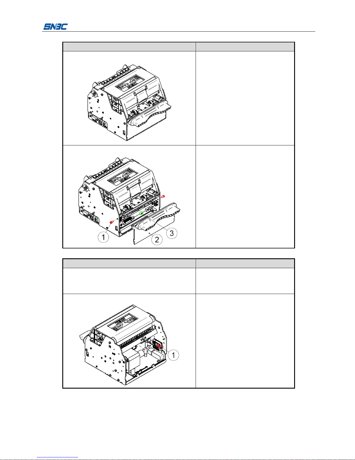
3.1.2 Disassemble the paper guide’s cover module
Figure Description
1.
Printer overview
Turn off the printer power.

BK-T6112 Service Manual
- 12 -
Figure Description
2.
Disassemble the two ST2.6x6 flat
self-tapping screws on both side of printer
with cross screw driver, and take off the
paper guide's cover module.
①—ST2.6×6 flat self-tapping screw
②—Paper guide's cover module
③—Mark sensor adjusting thumbwheel
④—Mark sensor socket
Note:
Be careful to keep the mark sensor
thumbwheel to avoid its missing.
When taking off the paper guide's cover
module, pull the plug of mark sensor cable
out of corresponding socket, and ensure
that the socket and the plug are not
damaged.
3.1.3 Disassemble the print motor module
Figure Description
1.
Follow "3.1.2 Disassemble the paper
guide's cover module", disassemble the
paper guide's cover module.
2.
Disassemble the two M3x6 pan head
screws with cross screw driver, and
take off the two Φ3 spring washers and
the print motor module.
①—M3×6 pan head screw
②—Φ3 spring washer
③—Print motor module
④—Print motor socket
Note: When taking off the print motor
module, pull out the plug of motor
cable out of corresponding socket, and
ensure that the socket and the plug are
not damaged.
BK-T6112 Service Manual
- 13 -
3.1.4 Disassemble the LED paper out path module
Figure Description
1.
Printer overview
Turn off the printer power.
2.
Disassemble the two M3×6 pan head
screws with cross screw driver and then
take off the LED paper out path module.
①—M3×6 pan head screw
②—LED paper out path module
③—LED socket
Note: When taking off the LED paper out
path module, pull the plug of LED cable out
of LED socket, and ensure that the socket
and the plug are not damaged.
3.1.5 Disassemble the Presenter module
Figure Description
1.
Follow "3.1.2 Disassemble the paper
guide's cover module", disassemble the
paper guide's cover module.
2.
Pull the plug of microswitch cable out of
corresponding socket, and ensure that the
plug and the socket are not damaged.
①—Microswitch socket
Table of contents
Other SNBC Printer manuals

SNBC
SNBC BTP-L580IIC User manual

SNBC
SNBC BTP-R180II Owner's manual

SNBC
SNBC BTP-R880NP Owner's manual

SNBC
SNBC BTP-P36 User manual

SNBC
SNBC BTP-P33 User manual

SNBC
SNBC BT-T080R User manual

SNBC
SNBC BTP-M280 User manual

SNBC
SNBC BTP-R880NPI User manual

SNBC
SNBC BTP-R580 User manual

SNBC
SNBC BTP-R880NP User manual

SNBC
SNBC BTP-R180II User manual

SNBC
SNBC BTP-R180II User manual

SNBC
SNBC BTP-M280 User manual

SNBC
SNBC BK-S216 User manual

SNBC
SNBC BTP-R990 User manual

SNBC
SNBC BTP-M300 Owner's manual

SNBC
SNBC BTP-R681 User manual

SNBC
SNBC BT-UC156 User manual

SNBC
SNBC BTP-2002NP User manual

SNBC
SNBC BT-T080 Owner's manual


