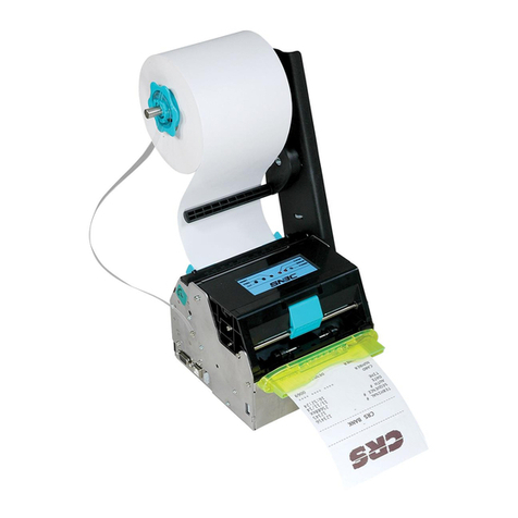
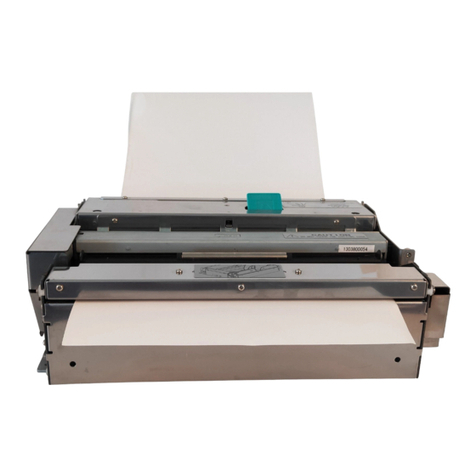
SNBC BT-T080R User manual

User’s Manual
Embedded Printer
BT-T080R
Shandong New Beiyang Information Technology Co., ltd.

BT-T080R User’s Manual
- 1 -
Declaration
Information in this document is subject to change without notice. SHANDONG NEW BEIYANG
INFORMATION TECHNOLOGY CO., LTD. (hereinafter referred to as “SNBC”) reserves the right to
improve products as new technology, components, software, and firmware become available. If users
need further data about this product, please feel free to contact SNBC or your local dealer.
No part of this document may be reproduced or transmitted in any form or by any means, electronic or
mechanical, for any purpose without the express written permission of SNBC.
Copyright
This manual was published in 2012 with copyright belonging to SNBC.
Printed in China
Version: 1.0
Trademark
Our registered trademark is .
Warning and Caution
Warning: Items shall be strictly followed to avoid injury or damage to body and equipment.
Caution: Items with important information and prompts for operating the printer.
SNBC has been approved of the following certificates:
ISO9001 Quality Control System Certification
ISO14001 Environmental Management System Certification
OHSAS18001 Occupational Health and Safety Management System Certification
IECQ QC080000 Hazardous Substance Process Management System Certification

BT-T080R User’s Manual
- 2 -
Safety Instructions
Before installing and using the printer, please read the following items carefully:
1. Safety warnings
Warning: Do not touch the cutter and tear-off bar of printer.
Warning: The print head is a thermal element and it is at a high temperature during printing or just
after operation, therefore do not touch it or its peripherals for reasons of safety.
Warning: The print head is an ESD-sensitive device. To avoid damage, do not touch either its
printing parts or connecting parts.
2. Caution
1) Install the printer at a flat and stable place.
2) Reserve adequate space around the printer so that the operation and maintenance can be
performed conveniently.
3) Keep the printer far away from water source, and do not expose the printer to direct sunlight, strong
light and heater.
4) Do not use or store the printer in a place exposed to heat of fire, moisture and serious pollution.
5) Do not place the printer in a place exposed to vibration and impact.
6) No dew condensation is allowed with the printer. In case of such condensation, do not turn on the
power until it has completely gone away.
7) Connect the AC power adapter to an appropriate grounding socket. Avoid sharing one electrical
socket with large power motors and other devices that may cause the fluctuation of voltage.
8) Disconnect the DC adapter when the printer is deemed to idle for a long time.
9) Don’t spill water or other electric materials into the printer. If this case happens, turn off the power
immediately.
10) Do not allow the printer to print when there is no paper installed, otherwise the print head and platen
roller will be damaged.
11) To ensure printing quality and products lifetime, use recommended paper or its equivalent.
12) Turn off the power when connecting or disconnecting interfaces to avoid damages to control board.
13) Set the printing darkness in a lower grade as long as the print quality is acceptable. This will help to
keep the print head durable.
14) Do not disassemble the printer without permission of a technician, even for repairing purpose.
15) Keep this manual carefully for reference.

BT-T080R User’s Manual
- 3 -
Contents
1 Outline ......................................................................................................................................................... 1
1.1 Brief introduction ................................................................................................................................. 1
1.2 Main features....................................................................................................................................... 1
2 Main technical index .................................................................................................................................... 2
2.1 Technical specifications....................................................................................................................... 2
2.2 Cutter technical parameters ................................................................................................................ 3
2.3 Status detection................................................................................................................................... 4
2.4 Print paper technical index .................................................................................................................. 5
2.4.1 Continuous paper parameter ........................................................................................................ 5
2.4.2 Marked paper parameter .............................................................................................................. 5
2.4.3 Recommended paper ................................................................................................................... 6
2.5 Print and cut position........................................................................................................................... 8
2.5.1 Print area ...................................................................................................................................... 8
2.5.2 Print and cut position .................................................................................................................... 8
3 Appearance and modules ............................................................................................................................ 9
3.1 Appearance and modules.................................................................................................................... 9
3.2 Overall size of printer......................................................................................................................... 11
3.2.1 Without paper outlet module ....................................................................................................... 11
3.2.2 With paper outlet module (optional) ............................................................................................ 11
3.2.3 With anti-pull and anti-jam module.............................................................................................. 11
3.3 Button and LED ................................................................................................................................. 12
3.4 Paper outlet module with LED (optional) ........................................................................................... 12
3.5 Anti-pull and anti-jam module (optional) ............................................................................................ 13
3.6 Product label ..................................................................................................................................... 13
4 Installing the printer ................................................................................................................................... 14
4.1 Unpacking ......................................................................................................................................... 14
4.2 Installing print mechanism ................................................................................................................. 14
4.2.1 Reserving paper roll loading space............................................................................................. 14
4.2.2 Installing and fixing print mechanism .......................................................................................... 15
4.3 Installing cantilever module (including the installation of the buffer module)................................ 16

BT-T080R User’s Manual
- 4 -
4.3.1 Cantilever angle: 0°..................................................................................................................... 16
4.3.2 Cantilever angle: 30°................................................................................................................... 18
4.3.3 Cantilever angle: 60°................................................................................................................... 19
4.3.4 Cantilever angle: 90°................................................................................................................... 21
4.3.5 Cantilever angle: -30° ................................................................................................................. 23
4.3.6 Cantilever angle: -60° ................................................................................................................. 25
4.3.7 Installing the paper roll baffle ...................................................................................................... 27
4.4 Installing and adjusting paper near end sensor ................................................................................. 28
4.4.1 Installing paper near end sensor................................................................................................. 28
4.4.2 Adjusting paper near end sensor ................................................................................................ 28
4.5 Connecting the AC power adapter .................................................................................................... 30
4.6 Connecting interface cable ................................................................................................................ 31
4.7 Installing and loading paper roll......................................................................................................... 32
4.7.1 Installing paper roll...................................................................................................................... 32
4.7.2 Loading paper............................................................................................................................. 34
4.8 Installing the driver ............................................................................................................................ 36
4.8.1 Typical installation....................................................................................................................... 36
4.8.2 Advanced installation .................................................................................................................. 38
5 Routine maintenance................................................................................................................................. 40
5.1 Cleaning print head and platen roller................................................................................................. 40
5.2 Cleaning paper near end sensor ....................................................................................................... 40
6 Interface signal .......................................................................................................................................... 41
6.1 RS-232 interface (optional)................................................................................................................ 41
6.1.1 Parameter ................................................................................................................................... 41
6.1.2 Interface linking terminal distribution and signal function ............................................................ 41
6.1.3 Demonstration of interface connection........................................................................................ 41
6.2 USB interface .................................................................................................................................... 42
6.2.1 Interface specification ................................................................................................................. 42
6.2.2 Interface signal definition and functions ...................................................................................... 42
6.2.3 USB interface connecting demonstration.................................................................................... 42
6.2.4 Interface connector ..................................................................................................................... 42

BT-T080R User’s Manual
- 5 -
6.3 Power interface ................................................................................................................................. 43
7 Troubleshooting ......................................................................................................................................... 44
7.1 Common errors and settlement ......................................................................................................... 44
7.2 Solutions for common errors ............................................................................................................. 46
Appendix....................................................................................................................................................... 48
Appendix 1 Self-test page ....................................................................................................................... 48
Appendix 2 Software tool......................................................................................................................... 50

BT-T080R User’s Manual
- 1 -
1 Outline
1.1 Brief introduction
BT-T080R printer is a high performance thermal printer with high adaptability and strong adjustability. It
can be widely used in various circumstances that need real-time printing on the spot, like financing,
telecommunication, etc.
BT-T080R can be connected with other devices through USB interface, and it provides drivers for
operating systems under Windows 2000/Windows XP/Windows Server 2003/Windows Vista/Windows
Server 2008/Windows 7.
1.2 Main features
¾Low noise, high printing speed;
¾Support continuous paper and marked paper (Do not recommend using inside paper because there is
risk of paper jams.);
¾Support paper width ranging from 48mm to 82.5mm;
¾Support paper roll with the maximum OD 180mm;
¾Support the paper roll with the ID ranging from 18mm to 60mm;
¾The mounting mode of paper roll adopts cantilever structure, and the cantilever supports the adjusting
angle of +90°, +60°, +30°, 0°, -30°, -60° and so on;
¾The paper outlet and the anti-pull and anti-jam module are optional, or there is no paper out module;
¾The communication interface USB, serial interface plus USB, and parallel interface are optional;
¾Convenient and quick paper loading;
¾Easy operation and maintenance;
¾Compatible with ESC/POS command.

BT-T080R User’s Manual
- 2 -
2 Main technical index
2.1 Technical specifications
Item Parameter (203dpi)
Print method Thermal printing
Resolution 203DPI
Paper width 48~82.5±0.5 mm
Max. 80mm (3.2″)
Print width
Max. 640 dots
Print height Max.: 480 mm, Min.: 5 mm
Print speed 150 mm/s
RAM memory SDRAM:128KB
Flash memory 1M/2M/4M
Print head temperature
detection Thermal resistor
Print head position
detection Microswitch
Paper/mark detection Photoelectric sensor
Paper near end
detection Photoelectric sensor
Printing
Communication
interface Serial interface plus USB, USB, parallel interface (optional)
Barcode CODE128, ITF, UPC-A, UPC-E, EAN13, EAN8
CODE39, CODE93, CODABAR, PDF417
Character set
Standard ASCII, compressed ASCII
Optional Asian character set (Simplified Chinese, traditional
Chinese, Japanese, Korean)
Character processing
All characters can be enlarged 1 to 6 times in vertical and
horizontal direction respectively;
Rotation Print (00, 900, 1800, 2700)
Bold, white/black reverse, underline
Barcode
Fonts
Graphics
Graphics Support BMP bitmap download to RAM, FLASH and direct
bitmap printing
Paper type Continuous paper/marked paper
Paper roll OD Max. 180mm
Paper roll core ID ф18~60mm
Paper thickness 60~100 um
Medium
Thermal layer Outward/Inward
Power
+24V power supply ,
room temperature,
average value
2.37A (25% duty ratio)
Print head lifetime ≥150 Km
Reliability
Cutter lifetime ≥1,500,000 cuts (65um thermal paper)

BT-T080R User’s Manual
- 3 -
Item Parameter (203dpi)
MTBF (main control
board) 360,000 hours
MTBF (printer) 5000 hours
Operation environment 0~50℃, 20~90%RH (40 )℃
Environment
Storage environment -40~60℃, 20~93% RH (40 )℃
Overall size 100(L) X 157(W) X 123(H) (printer mechanism)
Physics Character
Weight About 1.7Kg (without paper roll)
Table 2.1 Technical specification parameters
Notes:
1) DPI: dots printed for each inch (One inch is about 25.4mm);
2) The real printing speed is related with data transmission speed, print darkness, print duty ratio,
control commands and input voltage, which may be lower than that in the above table.
2.2 Cutter technical parameters
Item Parameter Remark
Cut method Slide blade
Cut time 252ms Time for every cut
Cut interval 3s 20 times every minute (Max.)
Paper type 60~100μm Thermal paper or common paper with
the same thickness
Work voltage 24VDC
Max. current 1.5A 24VDC
Cutter lifetime 1,000,000 times Including full cut and partial cut
Table 2.2 Cutter technical parameters
Full cut: The paper is cut off completely;
Partial cut: The paper is not cut off completely, with a little connection in the central area of the paper.

BT-T080R User’s Manual
- 4 -
2.3 Status detection
No. Detecting content Sensor type
1 Paper status Mechanical photoelectric
sensor
2 Mark Photoelectric sensor
3 Print head position Microswitch
4 Print head temperature Thermal resistor
Table 2.3 Status detection
Figure 2.3.1 Mark sensor 1
Figure 2.3.2 Mark sensor 2
Note:
When the mark sensor is located in position A, the mark is located in non-thermal layer;
When the mark sensor is located in position B, the mark is located in thermal layer.

BT-T080R User’s Manual
- 5 -
2.4 Print paper technical index
Figure 2.4.1 Paper roll with thermal layer outward Paper roll with thermal layer inward
2.4.1 Continuous paper parameter
Item Parameter Remark
Paper width 48~82.5mm Recommended: 70~82.5mm
Paper thickness 60~100μm
Paper roll OD ≤180mm
Paper roll ID 18~60mm Recommended: 18~25.4mm
Thermal layer position Inward, outward
The anti-pull and anti-jam module
doesn’t support paper roll with thermal
layer inward.
Table 2.4.1 Continuous paper parameters
Note:
Paper width: The mark width of paper holder includes 82.5mm, 80mm, 76mm, 70mm, 56mm and 48mm,
among which the 56mm and 48mm width paper need to adjust the firmware.
2.4.2 Marked paper parameter
Item Parameter Remark
Paper width 48~82.5mm Recommended: 70~82.5mm
Paper thickness 60~100μm
Paper roll OD ≤180mm
Paper roll ID 18~60mm Recommended: 18~25.4mm
Thermal layer position Inward, outward
The anti-pull and anti-jam module
doesn’t support paper roll with thermal
layer inward.
Table 2.4.2 Marked paper parameters
Note:
Paper width: The mark width of paper holder includes 82.5mm, 80mm, 76mm, 70mm, 56mn and 48mm,
among which the 56mm and 48mm width paper need to adjust the firmware and only adapt to Mark
position 2 (see Figure 2.4.2 Mark position).
1) Mark position
9For the paper mark over 79mm width, you can select thermal layer/non-thermal layer left, middle
and right (seven positions) as shown in Figure 2.4.2. Ensure beside marks cover mark sensor
completely (The space between mark sensor and the paper midline is 38.2 mm);
9For paper mark less than 79mm width, you can select thermal layer/non-thermal layer middle,

BT-T080R User’s Manual
- 6 -
position 4 (three positions). Ensure the midlines of mark and paper coincide;
9Mark position 4 can only be located in non-thermal layer.
2) In using marks, it is recommended to use the following parameters:
9L1 mark width: 8mm≤L1≤paper width
9L2 mark height: 4mm≤L2≤8mm
3) The reflectivity of marks is less than 10%, and the reflectivity of other parts of the ticket within mark
width along paper feed direction is over 85%.
Figure 2.4.2 Mark position
Note:
Because of the paper shaking in the feeding and paper difference in parameter, the position fixed by mark
may have a tolerance of ±1mm.
2.4.3 Recommended paper
Paper type Manufacturer
TF50KS-E2C Nippon Paper Industries CO., LTD.
F240AC/F220-VP Mitsubishi Paper Mill CO., LTD.
KF060-FEAH NEW OJI Paper CO., LTD.
F70NA FUJI PHOTO FILM CO., LTD.
FV230A1 MITSUBISHI PAPER MILL CO., LTD.
Table 2.4.3 Recommended paper
Caution:
zPlease use the recommended paper or its equivalents. Using other types of paper may affect print
quality and reduce the print head lifetime.
zDo not paste the paper to the shaft core.
zIf the paper comes in contact with chemicals or oil, it may discolor or be less heat sensitive, which will
greatly affect the print quality.
zDo not rub the paper surface with a nail or hard metal. Otherwise it may discolor.

BT-T080R User’s Manual
- 7 -
zWhen the temperature goes up to 70 degrees, paper will discolor. So please be careful to the effect of
temperature, humidity and sunlight in environment.

BT-T080R User’s Manual
- 8 -
2.5 Print and cut position
2.5.1 Print area
BT-T080R embedded print mechanism can be set according to user’s requirements, making the path adapt
to paper of various width.
L0: Paper width (48~82.5±0.5 mm);
L1: The maximum print width: 80mm;
L2: Print left margin (Adjustable)
L3: Print right margin (Adjustable)
L4: Top margin (Recommend no less than 5mm)
Figure 2.5.1 Print width
Note:
The path width of BT-T080R is wider than that of paper. While the paper is moving in the path, there is
some movement in the horizontal direction. In this way, there is some tolerance for print position in the
horizontal direction, which is normal and does not have an effect on using.
2.5.2 Print and cut position
Figure 2.5.2 Print and cut position
L1: 14.5mm

BT-T080R User’s Manual
- 9 -
3 Appearance and modules
3.1 Appearance and modules
Figure 3.1.1 BT-T080R printer
1. Print mechanism module 2. Cantilever paper shaft module
Figure 3.1.2 Print mechanism module
3. Button and LED 4. Mechanism spanner 5. Cutter
6. Tear-off bar 7. Power interface 8. Communication interface:
serial interface plus USB
Figure 3.1.3 Print mechanism module (with anti-pull and anti-jam module)
9. Communication interface: USB (optional)
11. Paper out module: anti-pull and anti-jam module (optional)

BT-T080R User’s Manual
- 10 -
Figure 3.1.4 Print mechanism module (with paper outlet module)
10. Communication interface: parallel interface (optional)
12. Paper out module: paper outlet (with LED) (optional)
Figure 3.1.5 Cantilever module
13. Cantilever 14. Buffer shaft 15.Paper roll shaft 16. Paper roll guide
17. Paper roll guide
moving knob 18. Paper roll baffle 19. Paper near end spanner

BT-T080R User’s Manual
- 11 -
3.2 Overall size of printer
3.2.1 Without paper outlet module
Figure 3.2.1 Overall size of printer without paper out module
3.2.2 With paper outlet module (optional)
Figure 3.2.2 Overall size of printer with paper outlet module
3.2.3 With anti-pull and anti-jam module
Figure 3.2.3 Overall size of printer with anti-pull and anti-jam module

BT-T080R User’s Manual
- 12 -
3.3 Button and LED
Figure 3.3.1 Button and LED
Button function explanation:
Button Function Description
FEED
Printer feeds paper after
this button is pressed
down.
FEED button
LED status explanation:
LED Status Description
ERROR flash/off
The printer is abnormal. /
The printer is normal.
POWER on/off
The printer is powered
on. /The printer is
powered off.
3.4 Paper outlet module with LED (optional)
Figure 3.4.1 Print mechanism module (with paper outlet module)
1. Paper outlet (transparent) 2. LED
The function of the module:
1) Increase the length of paper outlet;
2) LED flashes and prompts.
Please refer to 3.2.2 for its overall size.

BT-T080R User’s Manual
- 13 -
3.5 Anti-pull and anti-jam module (optional)
Figure 3.5.1 Print mechanism module (with anti-pull and anti-jam module)
1. Anti-pull and anti-jam module 2. Alarm label
Figure 3.5.2 Alarm label
Module function explanation:
1) When there is paper jam in the paper outlet, the module works and stops feeding paper to avoid
influencing user’s use and mechanism lifetime caused by mechanism paper jams.
2) When pulling paper in the horizontal or downwards direction, the module works and cuts paper to
avoid damaging printer.
Note: Anti-pull and anti-jam module can not be applied to paper roll with thermal layer inward.
Please refer to 3.2.3 for its overall size.
3.6 Product label
The content of the product label is as follows:
Figure 3.6.1 Product label content

BT-T080R User’s Manual
- 14 -
4 Installing the printer
4.1 Unpacking
Open the carton and check whether all items listed on the package list are included or have any damages.
In case of damages or missing items, please contact your dealer or the manufacture for assistance.
4.2 Installing print mechanism
4.2.1 Reserving paper roll loading space
The printer adopts the way of installing paper roll on one side. While operating and maintaining the printer,
reserve the extreme space for paper roll installation according to the space explanation of 4.3 Installing
cantilever module. Furthermore, you need to reserve the space for installing paper roll and connecting or
disconnecting power cable and interface cable as shown in the following figure, in order to effectively
ensure the reliability and convenience of printer operation.
Figure 4.2.1 Size of paper roll loading space reserved
Note: The size shown in the above figure is the minimum suggested size, which can be enlarged according
to real space.
Table of contents
Other SNBC Printer manuals
SNBC
SNBC BT-T080 Owner's manual
SNBC
SNBC BTP-R990 User manual
SNBC
SNBC BT-UC056III User manual
SNBC
SNBC BTP-P33 User manual
SNBC
SNBC BTP-R880NP Owner's manual
SNBC
SNBC BTP-R180II User manual
SNBC
SNBC BTP-M300 User manual

SNBC
SNBC BTP-R180II Owner's manual

SNBC
SNBC BTP-R580II Owner's manual

SNBC
SNBC BTP-R880NPI User manual


