Sola ARGO How to use

WWW.SOLAGRUPO.COM
ARGO
STARTING
MANUAL
MAINTENANCE AND DOSAGE
Trailed pneumatic seed drill

- 2 -
SOLÀ seed drills, planters and fertilizer spreaders are manufactured in a highly specialized environment
and our factory has a vast network of satised customers.
SOLÀ machines use highly advanced technology and are guaranteed to work without malfunctions
in a large variety of conditions. The SOLÀ machines are provided with easy-to-use and ecient devices
and perform excellently with only minimum operator maintenance.
This manual will help you use your SOLÀ product with the maximum eciency.
Certied quality system
2nd Edition – April 2021
Ref.: CN -811142/GB
Created by: M.A. SOLÀ
It is forbidden to copy any part of this manual.
Specications are subject to change or modication without notice.
The pictures included do not necessary show the standard version.

- 3 -
1. INTRODUCTION.......................................................................................................................................................... 5
2. SAFETY INSTRUCTIONS ............................................................................................................................................. 6
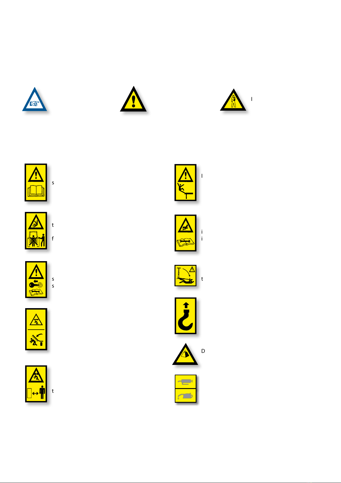
2.1 SAFETY SYMBOLS........................................................................................................................................................................ 6
2.2 GENERAL SAFETY INSTRUCTIONS ........................................................................................................................................... 7
2.3 LOADING AND UNLOADING INSTRUCTIONS......................................................................................................................... 7
3. GENERAL DESCRIPTION............................................................................................................................................. 8
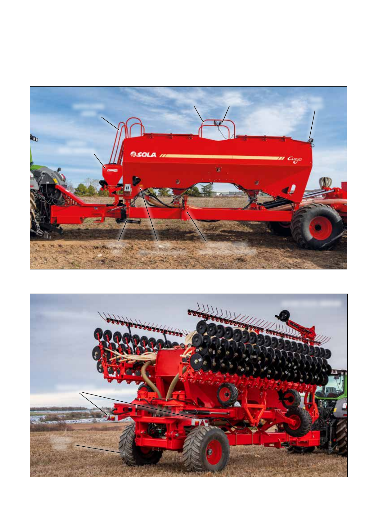
3.1 OVERVIEW OF THE MACHINE .................................................................................................................................................... 8
3.1.1 PLANTER SOWING UNIT.................................................................................................................................................. 10
3.1.2 SEEDER SOWING UNIT.................................................................................................................................................... 10
3.2 TECHNICAL CHARACTERISTICS (PLANTER).......................................................................................................................... 11
3.3 TECHNICAL CHARACTERISTICS (SEEDER)............................................................................................................................. 12
3.4 MACHINE IDENTIFICATION...................................................................................................................................................... 13
3.5 USE ACCORDING TO DESIGN................................................................................................................................................... 13
4. ESSENTIAL SOWING CONCEPTS................................................................................................................................14
4.1 TERRAIN....................................................................................................................................................................................... 14
4.2 SEEDS........................................................................................................................................................................................... 14
4.3 DEPTH.......................................................................................................................................................................................... 14
5. START-UP...................................................................................................................................................................15
5.1 HITCHING THE PLANTER TO THE TRACTOR.......................................................................................................................... 15
5.2 ELECTRICAL CONNECTIONS.................................................................................................................................................... 17
5.2.1 INDICATOR LIGHTS.......................................................................................................................................................... 17
5.2.2 ISOBUS............................................................................................................................................................................... 17
5.2.3 HYDRAULIC CONTROL AND WORK LIGHTS ............................................................................................................... 17
5.3 HYDRAULIC CONNECTIONS .................................................................................................................................................... 18
5.4 TRANSPORT POSITION ............................................................................................................................................................. 19
5.5 FILLING AND EMPTYING THE HOPPERS................................................................................................................................ 20
5.5.1 SEED HOPPERS (SEE PLANTER) ..................................................................................................................................... 21
5.5.2 CENTRAL HOPPERS......................................................................................................................................................... 21
5.5.3 CENTRAL HOPPERS FOR MICRO-GRANULAR PRODUCTS....................................................................................... 24
5.6 SUPPORT FEET............................................................................................................................................................................ 25
5.6.1 MAIN SUPPORT FOOT ..................................................................................................................................................... 26
5.6.2 SOWING EQUIPMENT SUPPORT FEET ......................................................................................................................... 27
5.7 PARKING...................................................................................................................................................................................... 27
5.8 AFTER WORKING WITH THE MACHINE.................................................................................................................................. 28
6. PLANTER MODEL ADJUSTMENTS ............................................................................................................................ 29
6.1 PLANTING DISTANCE BETWEEN SEEDS................................................................................................................................. 31
6.1.1 MECHANICAL TRANSMISSION....................................................................................................................................... 31
6.1.2 ELECTRICAL TRANSMISSION - ISOBUS ........................................................................................................................ 38
6.2 REPLACING THE SEED DISC..................................................................................................................................................... 38
6.3 FACTORS THAT AFFECT SEED QUALITY ................................................................................................................................ 39
6.3.1 ADJUSTING THE SELECTOR ........................................................................................................................................... 39
6.3.2 ADJUSTING THE SEED EJECTOR ................................................................................................................................... 40
6.3.3 DISTRIBUTOR SEED INLET ............................................................................................................................................. 41
6.4 SUCTION SYSTEM - FAN ........................................................................................................................................................... 43
6.5 DISABLING A SOWING UNIT....................................................................................................................................................44
6.5.1 DISABLING THE TRANSMISSION...................................................................................................................................44
6.5.2 LIFTING THE UNIT............................................................................................................................................................ 45
6.6 PLANTING DEPTH......................................................................................................................................................................46
6.7 PROSEM K SCRAPERS................................................................................................................................................................ 47
6.8 UNIT PRESSURE ON THE GROUND......................................................................................................................................... 47
6.9 CLOSING THE FURROW.............................................................................................................................................................48
6.9.1 WORKING WIDTH OF THE WHEEL................................................................................................................................. 49
6.9.2 PRESSURE ON THE SEED ................................................................................................................................................ 49
6.9.3 CASTER ANGLE................................................................................................................................................................. 50
TABLE OF CONTENTS

- 4 -
6.10 OPENING COMPONENTS........................................................................................................................................................ 50
6.10.1 ADJUSTING THE BLADE AND CLOD REMOVER ........................................................................................................ 51
6.10.2 ADJUSTING THE DISC FURROW OPENER ON THE PROSEM K UNIT (OPTIONAL) .............................................. 51
6.10.3 ADJUSTING THE BLADE OF THE PROSEM K DISC FURROW OPENER (OPTIONAL)............................................ 52
6.10.4 ADJUSTING THE ROTARY STUBBLE CLEANERS ON THE PROSEM K UNIT (OPTIONAL).................................... 52
6.11 ROTARY STUBBLE CLEANER WITH FOUR-BAR LINKAGE (OPTIONAL) ........................................................................... 53
6.12 PROSEM K SEED PRESS WHEEL (OPTIONAL) ...................................................................................................................... 54
7. SEEDER MODEL ADJUSTMENTS............................................................................................................................... 55
7.1 SOWING EQUIPMENT DEPTH CONTROL WHEELS ............................................................................................................... 56
7.2 SOWING UNIT DEPTH CONTROL WHEELS ............................................................................................................................ 57
7.3 HARROW ...................................................................................................................................................................................... 57
7.4 TRACK ERADICATOR.................................................................................................................................................................. 58
8. ADJUSTING THE CENTRAL HOPPERS ....................................................................................................................... 60
8.1 HIGH-CAPACITY HOPPERS....................................................................................................................................................... 61
8.1.1 ADJUSTING THE DISPENSER .......................................................................................................................................... 62
8.1.2 PRELIMINARY FLOW TEST .............................................................................................................................................. 63
8.1.3 ADJUSTING THE SEED DOSE - SEEDER MODEL..........................................................................................................66
8.2 CENTRAL MICRO-GRANULAR FERTILISER AND INSECTICIDE APPLICATOR .................................................................. 67
8.2.1 CHANGING A ROLLER ..................................................................................................................................................... 69
8.2.2 CALIBRATION TEST ......................................................................................................................................................... 70
8.2.3 PNEUMATIC SYSTEM - FAN............................................................................................................................................ 73
9. ADJUSTING THE MARKERS........................................................................................................................................74
10. MAINTENANCE ....................................................................................................................................................... 76
10.1 FREQUENCY OF CHECKS ........................................................................................................................................................ 77
10.2 FASTENERS ............................................................................................................................................................................... 78
10.3 CLEANING THE PLANTER....................................................................................................................................................... 78
10.4 GREASING AND LUBRICATION.............................................................................................................................................. 79
10.5 TYRE PRESSURE ....................................................................................................................................................................... 79
10.6 AUTOMATIC GEARBOX (according to model)....................................................................................................................80
10.7 FANS ........................................................................................................................................................................................... 80
10.8 ELECTRONICS........................................................................................................................................................................... 81

- 5 -
1- INTRODUCTION
It is essential to read and follow the instructions and
recommendations in this manual before operating the seed
drill or precision planter ARGO. Careful reading enables
maximum operator eciency, prevents accidents and damage,
and increases the planter’s capacity and life expectancy.
Please ensure that this manual has been read by any person
involved in performing operational tasks, (including
preparation, dealing with mechanical problems and
supervising the machine), maintenance (inspection and
technical assistance) and transport.
For your safety, please follow these technical safety
instructions as SOLÀ will not be responsible for damages
caused by not observing the information provided.
In the rst chapters you will nd the Technical Characteristics
and Safety Instructions. Basic concepts that are required
to operate the machine are explained in the Starting,
Adjusting and Maintenance sections.
The last part of this manual consists of Dosage Tables,
detailed by all types of seed, fertilizer, micro granular
fertilizer and micro granular pesticide.
MAQUINARIA AGRICOLA SOLÀ RESERVES
THE RIGHT TO CHANGE THE ILLUSTRATIONS,
TECHNICAL DATA AND TECHNICAL CHARAC-
TERISTICS AT ITS DISCRETION.

- 6 -
2. SAFETY INSTRUCTIONS
2.1 SAFETY SYMBOLS
En este manual encontrará tres tipos de símbolos de seguridad y de peligro:
TO WORK MORE EASILY
WITH THE PLANTER.
TO PREVENT DAMAGE
TO THE PLANTER AND
OPTIONAL EQUIPMENT.
TO PREVENT PHYSICAL
INJURY.
On the machine you will nd the following warning
pictograms:
Read the instructions carefully and observe the
safety advice given in the operating manual.
During the coupling maneuver, stay away from
the rear part of the tractor. Check nobody
stands in the operational area of the telescopic
folding parts. Risk of serious physical injury.
While maintaining or repairing the planter,
stop the tractor’s engine and prevent it from
starting. The ignition key must be removed.
Never stand under the sowing equipment
or swivel area of the machine’s extension tine
coulters.
Risk of serious physical injury.
Risk of being crushed when working under the
machine, please secure the machine to prevent
this risk. Risk of serious physical injuries.
It is forbidden to ride on the machine during
operation. Risk of serious physical injuries
caused by falling.
Danger of infection from escaping hydraulic
uid at high pressure! This can inict serious
injuries with potentially fatal consequences
if it passes through the skin and into the body.
Keep the hose lines in good condition. Risk
of serious physical injuries.
Never stand under the track markers nor inside
their action area. Risk of serious physical injury.
Coupling point for loading and unloading the
machine by crane.
Do not exceed maximum load
The parts signaled with this pictogram should
be kept in good condition and greased.
Kg. Max.

- 7 -
2.2 GENERAL SAFETY INSTRUCTIONS
- Before starting the machine, please check the
machine is in good condition for work and
is safe for road use.
- Check that visibility is clear around the
machine and there is no person in the
working area.
- In thoroughfare, please observe trac signs
and regulations.
- It is forbidden to ride on the machine or climb
into the machine when it is running.
- Before using the machine, the user must
be familiar with all operating elements.
- Please be extremely careful when coupling
and uncoupling the machine to the tractor.
- Never leave the tractor’s driver’s seat while
the machine is in operation.
- Do not deposit external elements inside the
hopper.
-
When maintaining the hydraulic system of the
planter, make sure that it is depressurized and
the tractor’s engine is o.
-
Please regularly check the condition of the
tubes and hosepipes in the hydraulic system.
These parts age naturally and their life should
not surpass 6 YEARS. Please replace when
necessary.
- Before transit with a machine with folding
frame coupled to the tractor, check that the
frame is completely folded.
- When raising the planter, the front axle
is unloaded. Ensure that the machine has
enough load to prevent it overturning. At this
time you must ensure that the condition
of both the steering and the brakes is optimal.
- During transit with the raised planter, block
the lowering switch. Before leaving the
tractor, lower the planter onto the ground
and remove the tractor’s starting key.
- Always use enough supporting elements
when maintaining the machine in a raised
position to prevent the machine from
lowering or falling.
- Before starting to plant a eld, evaluate the
risks coming from the terrain: pronounced
slopes, possible contact with high-voltage
overhead lines due to an uneven ground
or due to the position of the movable
or folding parts of the planter.
2.3 LOADING AND UNLOADING INSTRUCTIONS
THESE OPERATIONS SHOULD BE PERFORMED
ONLY BY QUALIFIED AND EXPERIENCED
PERSONNEL.
LOADING AND UNLOADING THE MACHINE
MUST BE PERFORMED, IF POSSIBLE, USING
A BRIDGE CRANE.
WHEN THE PLANTER IS DELIVERED,
IT SHOULD BE IMMEDIATELY CHECKED
TO DETECT POSSIBLE DAMAGES DURING
TRANSPORTATION OR MISSING PIECES. ONLY
THE IMMEDIATE REPORTING OF THIS TO THE
DELIVERER WILL RESULT IN COMPENSATION.

- 8 -
3. GENERAL DESCRIPTION
3.1 GENERAL OVERVIEW
FERTILISERFERTILISER
DISPENSERSDISPENSERS
HOPPER 1HOPPER 1
FERTILISERFERTILISER
DISTRIBUTOR HEADDISTRIBUTOR HEAD
SUCTION FANSUCTION FAN
Fig. 3.1Fig. 3.1
HOPPER 2HOPPER 2
FERTILISERFERTILISER
MACHINE VERSION:MACHINE VERSION: PLANTERPLANTER
HOPPER 3HOPPER 3
SEEDSEED
FERTILISER
SEED
DRIVEDRIVE
WHEELWHEEL
(according to model)(according to model)
FERTILISERFERTILISER
UNITUNIT
SOWINGSOWING
UNITUNIT
1st FAN1st FAN
(blow)(blow)
DRAWBARDRAWBAR
HOPPER 1 / HOPPER 2:HOPPER 1 / HOPPER 2: (according to model)(according to model)
· OPTION A:· OPTION A: SEED / SEEDSEED / SEED
· OPTION B:· OPTION B: SEED / FERTILISERSEED / FERTILISER
MARKERMARKER
Fig. 3.2Fig. 3.2 MACHINE VERSION:MACHINE VERSION: SEEDERSEEDER
HARROWHARROW
SOWINGSOWING
UNITUNIT
DEPTH CONTROLDEPTH CONTROL
WHEELWHEEL
TRACK ERADICATORTRACK ERADICATOR
1st FAN1st FAN
(blow)(blow)
FERTILISERFERTILISER
HEADHEAD
SEEDSEED FERTILISERFERTILISER
SEED and/orSEED and/or
FERTILISER DISPENSERSFERTILISER DISPENSERS
(according to model)(according to model)
DRAWBARDRAWBAR

- 9 -
Fig. 3.4Fig. 3.4 MACHINE VERSION:MACHINE VERSION: SEEDERSEEDER
TRANSPORT LIGHTSTRANSPORT LIGHTS
FLOTATIONFLOTATION
WHEELWHEEL
Fig. 3.3Fig. 3.3
HOPPER 4HOPPER 4
MICRO-GRANULARMICRO-GRANULAR
2nd FAN2nd FAN
(Micro-granular products)(Micro-granular products)
WORKWORK
LIGHTSLIGHTS
SUPPORTSUPPORT
FOOTFOOT
STOPPERS & LATCHESSTOPPERS & LATCHES
FOLDING SOWING EQUIPMENTFOLDING SOWING EQUIPMENT
HOPPER ACCESSHOPPER ACCESS
LADDERLADDER
HOPPER 2 ACCESSHOPPER 2 ACCESS
WALKWAYWALKWAY
HOPPERHOPPER
LIGHTSLIGHTS

- 10 -
3.1.1 PLANTER SOWING UNIT
1- Seed hopper.
2- Metering box provided with a selector to adjust the seed
distribution.
3- Planting depth controller.
4- Lever to adjust the pressure that the furrow closing wheels
exert onto the ground.
5- Lever to adjust the angle which aects the bearing of the
furrow closing wheels on the ground.
6- Furrow closing wheels : they cover the furrow where the
seed has been placed.
7- Planting depth control wheels.
8- Double disc furrow opener or seed discs: it forms the
furrow in which the seed will be placed.
9- Clod remover: prevents the clods from being in the way
of the planting depth control wheels.
10- Blade: helps to break the supercial earth crust.
11- Transmission group: transfers the main axle’s motion
to the metering box in order to turn the seed disc.
12- Parallelogram: allows the metering units to move
vertically to adapt to the terrain’s irregularities.
13- Lever to adjust the unit’s pressure: it adjusts the load
pressure exerted by the double-disc opener (8) onto the
ground.
14- Coupling mechanism: it allows to couple the unit
in raised position in order to exclude it.
Fig. 3.5Fig. 3.5
1
2
3
4
5
6789
10
11
13
14
12
PROSEM K
3.1.2 SEEDER SOWING UNIT
1- Meteringunit’s pressurespring:it adjusts the load pressure
exerted by the double-disc opener (3) onto the ground.
2- Blade: helps to break the supercial earth crust.
3- Double disc furrow opener or seed discs: it forms the
furrow in which the seed will be placed.
4- Depth control wheel.
5- Depth controller.
6- Adjustable scraper.
Fig. 3.6Fig. 3.6
1
2
3
4
6
5
DOUBLE DISC

- 11 -
Value Unit Value
Number of rows Quantity 16
Row spacing cm 70-75
Working Width m 11.2 - 12
Total Width on working position (without markers) m12.2
Total Width on working position (with markers) m 12.91 (closed markers) / 17.75 (one open marker)
Working Length m10.95
Working Heigth m3.7
Fertilizer hopper loading Heigth m3.15
Transport Width m3.95
Transport Length m8.53
Transport Heigth m4.395
Internal Distance between wheels cm 169.5
External Distance between wheels cm 280.5
Wheels Quantity x Dimension 2 x 650/60-R22.5 or 2 x 560/60-R22.5
Fertilizer hopper capacity Quantity x Capacity L 2 x 3,100
Fertilizer drive Electrical / Mechanical Electrical
Micro hopper capacity Quantity x Capacity L 2 x 185
Micro Drive Electrical / Mechanical Electrical
Seed hopper capacity Quantity x Capacity L 16 x 50
Metering unit drive for seed Electrical / Mechanical Electrical / Mechanical
Markers Machine Centre / Tractor Wheel Tractor Wheel
Base weigth (minimun) kg 8,320
Hydraulic Connections
Quantity and use
SA = Single-Acting
DA = Double-Acting
1 DA, 4 SA + 1 free return (ELEKTRA with micro)
1 DA, 3 SA + 1 free return (ELEKTRA without micro or mechanical
with micro)
Oil Flow requirement (minimum) L x application
140 l/min ELEKTRA with micro
120 l/min ELEKTRA without micro or mechanical with micro
100 l/min mechanical without micro
Power requirement (minimun) HP 240
Connection pin with tractor (diameter) mm 50
Maximum fertilizer dosage at 8 km/h Kg/Ha 300
Maximum micro fertilizer dosage at 8 km/h Kg/Ha 40
3.2 TECHNICAL CHARACTERISTICS (PLANTER)

- 12 -
Value Unit Value
Number of rows Quantity 76
Row spacing cm 15.8
Working Width m12
Total Width on working position (without markers) m11.95
Total Width on working position (with markers) m 12.91 (closed markers) / 17.75 (one open marker)
Working Length m10.97
Working Heigth m3.7
Fertilizer hopper loading Heigth m3.15
Transport Width m3.66
Transport Length m8.53
Transport Heigth m4.395
Internal Distance between wheels cm 169.5
External Distance between wheels cm 280.5
Wheels Quantity x Dimension 2 x 650/60-R22.5 or 2 x 560/60-R22.5
Seed/Fertilizer hopper capacity Quantity x Capacity L 2 x 3,100
Seed/Fertilizer drive Electrical / Mechanical Electrical
Markers Machine Centre / Tractor Wheel Tractor Wheel
Base weigth (minimun) kg 8,320
Hydraulic Connections
Quantity and use
SA = Single-Acting
DA = Double-Acting
1 DA, 3 SA + 1 free return
Oil Flow requirement (minimun) L100 l/min
Power requirement (minimun) HP 240
Connection pin with tractor (diameter) mm 50
Maximum seed dosage a 10 km/h Kg/Ha 400
Maximum seed/fertilizer dosage a 10 km/h Kg/Ha 200/200
3.3 TECHNICAL CHARACTERISTICS (SEEDER)

- 13 -
3.4 IDENTIFICATION OF THE MACHINE
All machines are supplied with a NAMEPLATE on the drawbar,
detailing:
1- Manufacturer’s name and address.
2- Model number of the machine.
3- Machine type.
4- Serial number.
5- CE Marking and year of manufacture (to last digits).
Fig. 3.7Fig. 3.7
22
33
44
55
11
3.5 USE ACCORDING TO DESIGN
The ARGO planter has been manufactured specically for
sowing cereals and other grain seeds and spreading fertiliser
(according to model).
The machine has been designed to be trailed by a farm
tractor.
If any other use of the machine results in it being damaged,
the manufacturer accepts no responsibility for this.
You must comply with all legal provisions regarding safety
on the machines, road safety and occupational health
and safety.
Any modications made by the user will invalidate the manu-
facturer's warranty for any resulting damage that may occur.
Avoid using wet seeds and fertilisers. Using these may clog
or break the components.
MAQUINARIA AGRÍCOLA SOLÀ RESERVES
THE RIGHT TO CERTIFY ITS MACHINES IN THE
MARKETS THAT IT DEEMS NECESSARY.
DEPENDING ON THE CONDITIONS OF USE
DEFINED BY THE MACHINE'S END USER AND
ANY OPTIONAL EQUIPMENT INCLUDED,
DURING TRANSPORTATION THE MACHINE
MAY NOT COMPLY WITH THE CURRENT
REGULATIONS FOR HIGHWAYS AND PUBLIC
ROADS. COMPLYING WITH THE ROAD TRAFFIC
REGULATIONS IS THE SOLE RESPONSIBILITY
OF THE END USER OF THE MACHINE.
MAQUINARIA AGRÍCOLA SOLÀ WILL NOT
BE LIABLE UNDER ANY CIRCUMSTANCES FOR
THE CONSEQUENCES OF A VIOLATION OF THE
CURRENT ROAD TRAFFIC REGULATIONS IN THE
COUNTRY WHERE ITS MACHINES ARE SENT.
Mod.Mod.
TypeType
NumberNumber
MAQUINARIA AGRÍCOLA SOLÀ S.L.MAQUINARIA AGRÍCOLA SOLÀ S.L.
CTRA. DE IGUALADA, S/NCTRA. DE IGUALADA, S/N
08280 CALAF (BCN)08280 CALAF (BCN)
SPAINSPAIN

- 14 -
4. ESSENTIAL SOWING CONCEPTS
4.1 TERRAIN
The better the soil condition, the better the sowing quality.
Work is more dicult on big clods or uneven furrows.
Although machines resist harsh conditions, if the seedbed
does not satisfy apropriate conditions then the sowing
quality will suer.
4.2 THE SEED
It is essential to use high-quality, clean and uniform seeds.
4.3 SEED PLANTING DEPTH
The seed planting depth has consequences for tillering,
as well as for the plant’s strength and its ability to resist
frostbite or drought. The parent shoot grows from 1 to 2 cm
under the ground, whatever the depth of the seed.
Planting deeper does not necessarily mean getting deeper
roots. Only a few roots grow from the lower part of the seed.
Most of them grow from a parent shoot close to ground level.
Normal Planting Depth: from 2 to 4 cm
Fig. 4.1Fig. 4.1
SEEDSEED
TilleringTillering
nodenode
• Thick stem, short rhizome
and resistant to frostbite.
• Multiple tillering providing
from 3 to 6 shoots and a lot
of blades, from 6 to 10.
• Deep and thick roots,
approximately 5 cm in width
and 10-12 cm in depth.
• With less grains per sowing
square metre, more ears
are obtained.
Deeper Planting: from 5 to 6 cm
Fig. 4.2Fig. 4.2
SEEDSEED
RhizomeRhizome TilleringTillering
nodenode
• Fine stem, rhizome
exposed to frostbite.
• Late and weak tillering, 1
or zero shoots and only
a few blades, 3-4 aprox.
• Medium quality roots
of approximately 3 cm
inwidth and5 cm indepth.
• More grains per sowing
square metre are required
to obtain the same
number of ears as in the
previous case.
Very deep planting: from 8 to 10 cm
Fig. 4.3Fig. 4.3
Rhizome
Seed
Tillering
node
• Very ne stem. No tillering
and only one blade.
• Seed runs out of supplies
by growing a long rhizome
which frostbite can easily
cut.
• The plant takes weak
roots, approximately 1 cm
in width and 3 cm in depth.
• Twice the number of grains
per sowing metre are
required to obtain the same
number of ears as in the
rst case.
IN VERY COLD PLACES, REPEATED FROSTBITE
CAN HAVE A HONEYCOMB EFFECT ON THE
GROUND’S MOST SUPERFICIAL LAYER. IN THIS
CASE THE PLANT’S VERY FIRST ROOTS CAN
LOOSEN AND THE PLANT WILL DIE. SLIGHTLY
DEEPER PLANTING IS RECOMMENDED
AND IF POSSIBLE, THE USE OF ROLLERS
TO COMPACT THE EARTH TO BETTER PROTECT
THE SEEDS.
WHEN STARTING THE MACHINE, FURROWS
WILL NOT CONTAIN ANY SEEDS FOR A METRE.
WHEN STOPPING THE MACHINE, SEEDS
WHICH WERE PREVIOUSLY INSIDE THE SEED
HOSES, SLIDE FROM THE MACHINE AND END
UP PILED ON THE GROUND. TAKE THIS INTO
ACCOUNT WHEN STOPPING AND STARTING
THE MACHINE IN ORDER TO ACHIEVE MORE
ACCURACY.
ALWAYS WORK AT A UNIFORM SPEED
AS SUDDEN ACCELERATING AND SLOWING
DOWN WILL CAUSE AN IRREGULAR SEEDS
DISTRIBUTION.
THE RECOMMENDED PLANTING DEPTH
VARIES DEPENDING ON THE TYPE OF CROP,
SO WE RECOMMEND THAT THE FARMER
GETS PROFESSIONAL ADVICE FROM EXPERTS
OR SPECIALISTS IN THIS AREA.

- 15 -
5. STARTING
Before working with the planter, the following points should
be taken into account:
• Check that all the components of the planter are correctly
lubricated. Grease periodically the mechanical elements.
• Check the tyre pressure.
• In the case that the planter is equipped with an automatic
transmission gearbox, check the oil level.
• Check that the ducts of the hydraulic system of the planter
are in good condition.
• Check that the ducts of the suction system are in good
condition.
• Adjust the height of the front hitch according to the tractor
being used.
• Check the tightening torque of the wheel studs.
After coupling the planter to the tractor:
• Check the planter is correctly coupled to the tractor.
• Before starting the planter, become familiar with all its
parts and adjustments.
• Start the planter when the hopper is empty in order to free
the pipes from condensation water or impurities.
• Adjust the planter and all its components to the type
of terrain to be planted on.
5.1 COUPLING TO THE TRACTOR
The ARGO planter features a ring-type hitch or ball hitch.
MAKE SURE THAT NO PERSON OR OBJECT
IS EVER BETWEEN THE PLANTER AND THE
TRACTOR WHEN COUPLING OR UNCOUPLING
BOTH MACHINES.
THESE OPERATIONS REQUIRE THE UTMOST
ATTENTION TO PREVENT PHYSICAL INJURIES
TO THE PERSON OPERATING THE MACHINE.
For the coupling maneuver, follow these steps:
1- Connect the planter's rotating ring or ball hitch to the
tractor, at the coupling point for trailers (Fig. 5.1).
2- Raise the machine's support foot.
Fig. 5.1Fig. 5.1
3- Connect the following plugs from the hydraulic system
to the tractor’s hydraulic connections
THE HYDRAULIC CONNECTIONS NECESSARY FOR
THE MACHINE ARE DETAILED IN SECTION 5.3
HYDRAULIC CONNECTIONS.

- 16 -
4- Connect the 7-pin electrical plug to the tractor for the
indicator lights and work lights.
5- Connect the ISOBUS cable to the tractor's ISOBUS socket.
6- Connect the 3-pin cable.
Fig. 5.2Fig. 5.2
BEFORE RUNNING WITH THE MACHINE, PLEASE
CHECK THAT IT IS CORRECTLY COUPLED TO THE
TRACTOR.
TO UNCOUPLE THE MACHINE FROM THE
TRACTOR, PERFORM THE FORMER STEPS IN THE
REVERSE ORDER.
IMPORTANT:
WHEN UNCOUPLING THE
MACHINE FROM THE TRACTOR, TAKE CARE NOT
TO LEAVE ANY HYDRAULIC OR ELECTRICAL
CIRCUIT CONNECTED TO THE TRACTOR.
IMPORTANT:
IN THE EVENT OF A FAULT,
ALWAYSCHECKTHEELECTRICALCONNECTIONS.
7- With the application off (APP OFF), unfold the chassis
and distributor heads (Fig. 5.3). To do this, operate the
chassis's hydraulics that are marked in yellow.
FigFig. 5.3. 5.3
IMPORTANT:
THE DISTRIBUTOR HEADS MUST
BE IN A FULLY UPRIGHT POSITION. OTHERWISE,
CONTINUE DELIVERING A FLOW TO THE
HYDRAULIC CIRCUIT.
IMPORTANT:
PUT THE SOWING UNIT'S
HYDRAULIC CIRCUIT IN THE FLOAT POSITION.
8- With the application on (APP ON) (Fig. 5.4), unfold the
marker (according to model); to do this, operate the
markers' hydraulics that are marked in yellow. To change
markers, apply pressure to fold up one marker and then
apply pressure again to unfold the opposite marker.
FigFig. 5.4. 5.4

- 17 -
5.2 ELECTRICAL CONNECTIONS
The machine has electrical connections for:
• INDICATOR LIGHTS.
• ISOBUS CONNECTION.
• HYDRAULIC CONTROL AND WORK LIGHTS.
IMPORTANT:
CONNECT ALL OF THE CABLES;
OTHERWISE THE MACHINE WILL NOT WORK.
5.2.1 INDICATOR LIGHTS
All models have a 7-pin connector for indicator lights.
7-pin connector diagram and table (according to ISO 1724):
1
5
4
7
6
3
2
Pin
no.
Stan-
dard FUNCTION
1LLeft indicator light
254G Fog light
331 Earth
4RRight indicator light
558R Right position lamp
654 Brake
758L Left position lamp
5.2.2 ISOBUS
The machine must have the 9-pin
connector (according to ISO 11783)
to allow the machine to connect to the
tractor's ISOBUS system.
3
8
7
1
2
6
4
59
WHENTRANSPORTING THE MACHINE ON PUBLIC
ROADS, MAKE SURE THAT THE WORK LIGHTS
ARE SWITCHED OFF.
5.2.3 HYDRAULIC CONTROL AND WORK
LIGHTS
+-
The machine is powered via the 3-pin
connector (in accordance with standard
DIN 9680).
IMPORTANT:
IF THIS CABLE IS NOT
CONNECTED, IT WILL NOT BE POSSIBLE TO
COMPLETE ANY MOVEMENT WITH THE CHASSIS
OR MARKERS.
To turn the work or hopper lights on or o, follow these steps:
Fig. 5.5Fig. 5.5
Fig. 5.6Fig. 5.6

- 18 -
Fig. 5.7Fig. 5.7
Fig. 5.8Fig. 5.8
Turn on the desired light; work lights (green) and/or hopper
lights (yellow)
Fig. 5.9Fig. 5.9
5.3 HYDRAULIC CONNECTIONS
The machine requires hydraulic connections to:
• FOLD/UNFOLD AND ROTATE THE SOWING WINGS AND
FOLD/UNFOLD THE MARKERS (according to model).
A double outlet. Maximum 80 l/min.
• LOWER AND RAISE THE SOWING EQUIPMENT.
A single outlet.
• HYDRAULIC BLOW FAN FOR THE PNEUMATIC CONVEYING
OF THE MAIN HOPPERS (1 & 2); HOPPERS FOR MICRO-
GRANULAR PRODUCTS (according to model); AND POWER
GENERATION (according to model).
A single outlet.
• HYDRAULIC SUCTION FAN (according to model).
A single outlet.
• HYDRAULIC SERVICE BRAKE.
A single outlet.
• FREE RETURN FOR ALL SINGLE OUTLETS.
The dierent hydraulic circuits can be distinguished
by colours, as shown on the table below:
CAP
COLOUR DESCRIPTION
YELLOW For FOLDING/UNFOLDING the chassis (APP OFF)
For FOLDING/UNFOLDING markers (APP ON)
GREEN To RAISE/LOWER the sowing equipment
RED Blow fan OPERATION
BLUE Suction fan OPERATION
RED Hydraulic circuit for the service brake
RED For the FREE RETURN
VACUUMVACUUM
H1/H2H1/H2

- 19 -
IMPORTANT:
THE MAXIMUM FLOW RATE FOR
THE HYDRAULIC CIRCUITS WITH YELLOW AND
GREEN CAPS MUST NOT EXCEED 80 L/min.
ALWAYS PERFORM MAINTENANCE TASKS
ON THE MACHINE WITH THE HYDRAULIC
CONNECTIONS DISCONNECTED.
WHEN CLOSING OR OPENING THE FOLDABLE
PARTS AND MARKERS, MAKE SURE THAT
THERE IS NOBODY NEAR TO THE MACHINE
OR ANY FOREIGN OBJECTS IN THE PATH
OF MOVING PARTS.
IF THE MACHINE DOES NOT RESPOND WHEN
HYDRAULIC PRESSURE IS BEING DELIVERED,
CHECK THAT THE HYDRAULIC AND ELECTRICAL
CONNECTORS ARE PROPERLY CONNECTED
TO THE TRACTOR'S DISTRIBUTOR AND THAT
THE HYDRAULIC CIRCUITS' SHUT-OFF VALVES
ARE OPEN.
KEEP THE HYDRAULIC PIPES IN A GOOD
CONDITION. PRESSURISED OIL CAN PENETRATE
THE SKIN AND CAUSE VERY SERIOUS INJURIES.
THE HYDRAULIC CONNECTORS SUPPLIED
BY THE MANUFACTURER MUST BE USED.
5.4 TRANSPORT POSITION
With the machine hitched to the tractor and the hydraulic
circuits connected to it, follow these steps:
1- Check that all of the seed hoppers are closed properly
(according to model) (Fig. 5.10).
Fig. 5.10Fig. 5.10
2- Close the valve of the seed distributors (according
to model); to do this loosen the knob, turn the lever
to its lowest position and tighten the knob to fix it there.
Repeat this process for all sowing units (Fig. 5.11).
Fig. 5.11Fig. 5.11
3- Place all of the sowing unit's levers in the transport position
(in red, Fig. 5.12) (according to model).
Fig. 5.12Fig. 5.12

- 20 -
4- Fold up the markers (according to model). To do this,
the application must be on (APP ON).
5- Fold up the distributor heads and chassis. To do this,
the application must off (APP OFF).
IMPORTANT: MAKE SURE THAT THE
DISTRIBUTOR HEADS ARE FULLY FOLDED UP
BEFORE ROTATING AND FOLDING UP THE
CHASSIS.
6- When the chassis is folded, continue delivering
hydraulic pressure for a further 5 seconds.
IMPORTANT: BEFORE TRANSPORTING THE
MACHINE ON PUBLIC HIGHWAYS OR ROADS,
MAKE SURE THAT THE LATCHES ARE CLOSED
(FIG. 5.13).
Fig. 5.13Fig. 5.13
IMPORTANT: BEFORE TRANSPORTING THE
MACHINE ALONG ANY TYPE OF ROAD, MAKE
SURE THAT THE SERVICE BRAKES ARE IN GOOD
WORKING ORDER, BOTH ON THE TRACTOR
AND ON THE MACHINE.
IMPORTANT: BEFORE FOLDING THE
MACHINE, MAKE SURE THAT THE SOWING
UNITS ARE IN THE WORKING POSITION AND
NOT DISABLED.
5.5 FILLING AND EMPTYING THE HOPPERS
The machine has several hoppers, depending on the model
and its conguration:
PLANTER version:
· SEED HOPPERS ON THE SOWING UNITS.
· CENTRAL HOPPERS FOR MICRO-GRANULAR FERTILISER.
· CENTRAL HOPPERS FOR MICRO-GRANULAR PRODUCTS.
SEEDER version:
· CENTRAL HOPPERS FOR SEEDS and/or MICRO-GRANULAR
FERTILISER.
· CENTRAL HOPPERS FOR MICRO-GRANULAR PRODUCTS.
In order to safely and quickly ll the hoppers, the best way
is using a WORM DRIVE. A hydraulic crane can also be used
to raise the BIG BAG above the hopper in order to ll it. Check
that the whole bag volume ts into the hopper. To secure
the BIG BAG to the crane, follow the instructions provided
by the its manufacturer.
IMPORTANT: BEFORE FILLING THE HOPPERS,
FIRST CHECK THAT NO FOREIGN OBJECTS
HAVE BEEN LEFT INSIDE.
IMPORTANT: BEFORE FILLING THE HOPPER,
MAKE SURE THAT THE VALVES AND DRAIN
OUTLET ARE PROPERLY CLOSED.
CHECK THAT THE PLANTER IS EMPTY, CLEAN
AND DRY.
DO NOT DEPOSIT EXTERNAL ELEMENTS INSIDE
THE HOPPERS. BEFORE FILLING IT CHECK THAT
IT CONTAINS NO OBJECT AND THE PRODUCT
OUTLET IS NOT BLOCKED.
IMPORTANT: FOR LOADING AND EMPTYING THE
HOPPER, THE OPERATOR MUST USE APPROPRIATE
PERSONAL PROTECTIVE EQUIPMENT (PPE) (DUST
MASK, GLASSES AND GLOVES).
Table of contents
Other Sola Farm Equipment manuals