8
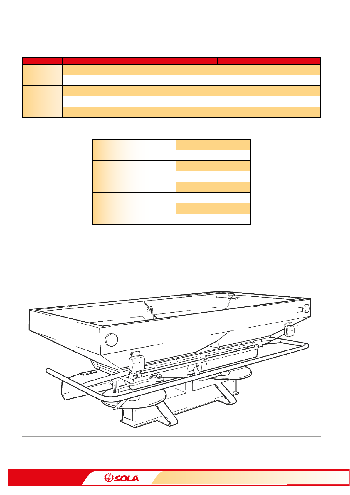
TECHNICAL CHARACTERISTICS
3.2 USE ACCORDING TO DESIGN
- Fertiliser spreaders D-903 & D-903 PLUS have been de-
signed for normal use in agricultural work, especially for
spreading with mineral products.
- If the machine is used in circumstances other than the above,
SOLÁ will not be held responsible for any damage caused.
- The user must observe all regulations concerning safety, traf-
c and hygiene.
- If the machine is modied by the user, the manufacturer’s
warranty is cancelled.
- SOLÁ will not be held responsible for any damage caused.
3.3 GENERAL SAFETY INSTRUCTIONS
BEFORE STARTING THE MACHINE, PLEASE CHECK
THE MACHINE IS IN GOOD CONDITION FOR WORK
AND IS SAFE FOR ROAD USE.
CHECK THAT VISIBILITY IS CLEAR AROUND THE MA
CHINE AND THERE IS NO PERSON IN THE WORKING
AREA.
IN THOROUGHFARE, PLEASE OBSERVE TRAFFIC
SIGNS AND REGULATIONS.
IT IS FORBIDDEN TO RIDE ON THE MACHINE OR
CLIMB INTO THE MACHINE WHEN IT IS RUNNING.
BEFORE USING THE MACHINE, THE USER MUST BE FA
MILIAR WITH ALL OPERATING ELEMENTS.
PLEASE BE EXTREMELY CAREFUL WHEN COUPLING
AND UNCOUPLING THE MACHINE TO THE TRACTOR.
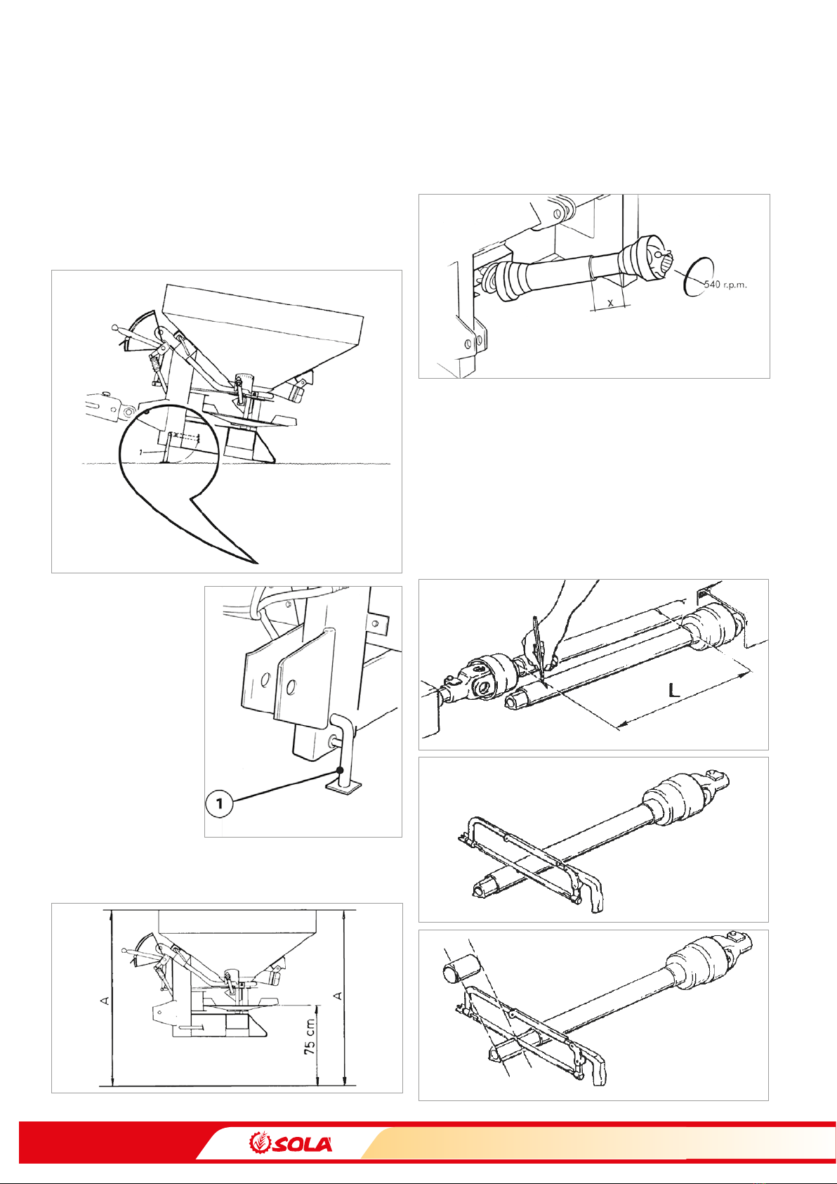
PLEASE CHECK THAT THE PTO SHAFT IS IN GOOD
CONDITION AND WELL PROTECTED. PREVENT THE
PROTECTIVE TUBE FROM TURNING BY HOLDING
BOTH THE TUBE AND CHAIN PROVIDED FOR THIS
PURPOSE.
MOUNT THE PTO SHAFT’S TRANSMISSION ONLY
WHEN THE TRACTOR’S ENGINE IS OFF.
BEFORE CONNECTING THE PTO SHAFT, BE SURE THAT
THE DANGER ZONE SURROUNDING THE MACHINE IS
CLEAR.
NEVER LEAVE THE TRACTOR’S DRIVER’S SEAT WHILE
THE MACHINE IS IN OPERATION.
DO NOT DEPOSIT EXTERNAL ELEMENTS INSIDE THE
HOPPER.
WHEN MANTAINING THE HYDRAULIC SYSTEM OF
THE FERTILISER SPREADER, MAKE SURE THAT IT IS
DEPRESSURISED AND THE TRACTOR’S ENGINE IS OFF.
PLEASE REGULARLY CHECK THE CONDITION OF THE
TUBES AND HOSEPIPES IN THE HYDRAULIC SYS
TEM. THESE PARTS AGE NATURALLY AND THEIR LIFE
SHOULD NOT SURPASS 6 YEARS. PLEASE REPLACE
WHEN NECESSARY.
WHEN RAISING THE FERTILISER SPREADER, THE
FRONT AXLE IS UNLOADED. ENSURE THAT THE MA
CHINE HAS ENOUGH LOAD TO PREVENT IT OVER
TURNING. AT THIS TIME YOU MUST ENSURE THAT
THE CONDITION OF BOTH THE STEERING AND THE
BRAKES IS OPTIMAL.
DURING TRANSIT WITH THE RAISED FERTILISER
SPREADER, BLOCK THE LOWERING SWITCH. BEFORE
LEAVING THE TRACTOR, LOWER THE FERTILISER
SPREADER ONTO THE GROUND AND REMOVE THE
TRACTOR’S STARTING KEY.
ALWAYS USE ENOUGH SUPPORTING ELEMENTS
WHEN MAINTAINING THE MACHINE IN A RAISED PO
SITION TO PREVENT THE MACHINE FROM LOWERING
OR FALLING.
FILL THE FERTILISER SPREADER WHEN IT IS IN ON THE
GROUND, ENSURE THE TRACTOR ENGINE IS OFF AND
THE FERTILISER OUTLET OPENINGS ARE CLOSED.
ALWAYS CONNECT GENTLY THE PTO SHAFT’S CLUTCH
IN ORDER TO PROTECT THE FERTILISER SPREADER.
OTHERWISE THE MACHINE COULD BE SERIOUSLY
DAMAGED.
BE CAREFUL WHEN FILLING THE FERTILISER SPREAD
ER AND TAKING INTO A FIELD WHICH IS FAR AWAY. IT
IS POSSIBLE THAT THE FERTILISER COMPACTS AT THE
BOTTOM OF THE HOPPER AND THE OUTLET OPEN
INGS ARE OBSTRUCTED. IN THIS CASE IT WILL BE NEC
ESSARY TO COMPLETELY OPEN THE OUTLETS, LET THE
PTO SHAFT’S CLUTCH SLOWLY IN AND SPREAD SOME
FERTILISER. AFTER THIS OPERATION, PLACE THE AD
JUSTING LEVERS IN THE POSITION CORRESPONDING
TO THE CHOSEN FLOW AND SPREAD NORMALLY.
NEVER DELIBERATELY CAUSE THE EXIT OF THE FERTIL
ISER FROM THE UPPER PART OF THE HOPPER. THERE
IS A SERIOUS RISK OF OBSTRUCTING THE AGITATOR.
AFTER EACH WORKING DAY, THE SPREADING VANES
AND THEIR TIGHTING SCREWS SHOULD BE CHECKED.
THEY SHOULD BE REPLACED WHEN THEY ARE VISI
BLY WORN OUT, SINCE THE WEAR IS CAUSED BY THE
CONTACT WITH THE FERTILISER AND IT IS BECOMES
WORSE WHEN THE FERTILISER IS MORE ABRASIVE.
CONSEQUENCES OF WORN OUT SPREADING VANES
ARE A BAD IRREGULAR SPREADING AND, ESPECIALLY,
THE RISK CAUSED BY FRAGMENTS DETACHED FROM
THE SPREADING VANES.