Sola Kibli 2010 How to use

MAQUINARIA AGRÍCOLA
STARTING MANUAL
MAINTENANCE
DOSAGE
SPARE PARTS
Please read and follow this operating manual before putting the machine into operation.

2
,62
%85($89(5,7$6
&HUWLILFDWLRQ
SOLÀ seed drills, fertiliser spreaders and front hoppers are manufactured in a highly specialized environ-
ment and our factory has a vast network of satised customers.
SOLÀ machines use highly advanced technology and are guaranteed to work without malfunctions in a
large variety of conditions. They SOLÀ machines are provided with easy-to-use and ecient devices and
perform excellently with only minimum operator maintenance.
This manual will help you use your SOLÀ product with the maximum eciency.
CERTIFIED QUALITY SYSTEM
2ND Edition – Desember 2014
Ref.: CN-811073/GB
Created by: SOLÀ
It is forbidden to copy any part of this manual.
Specications are subject to change or modication without notice.
The pictures included do not necessary show the standard version.

3
TABLE OF CONTENTS
1. INTRODUCTION................................................................................................................................................... 5
2. TECHNICAL CHARACTERISTICS........................................................................................................................... 6
2.1 OVERVIEW................................................................................................................................................................. 6
2.2 TECHNICAL CHARACTERISTICS ............................................................................................................................ 6
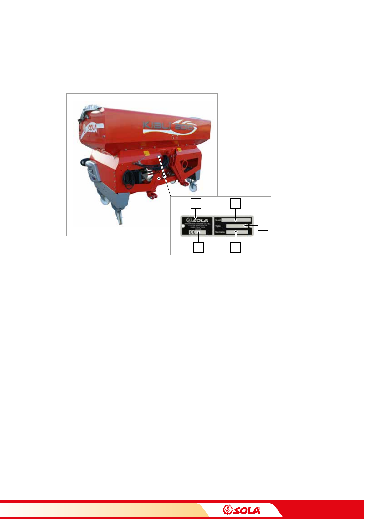
2.3 MACHINE IDENTIFICATION.................................................................................................................................... 7
2.4 STANDARD EQUIPMENT ........................................................................................................................................ 7
2.5 OPTIONAL EQUIPMENT.......................................................................................................................................... 7
3. SAFETY INSTRUCTIONS....................................................................................................................................... 8
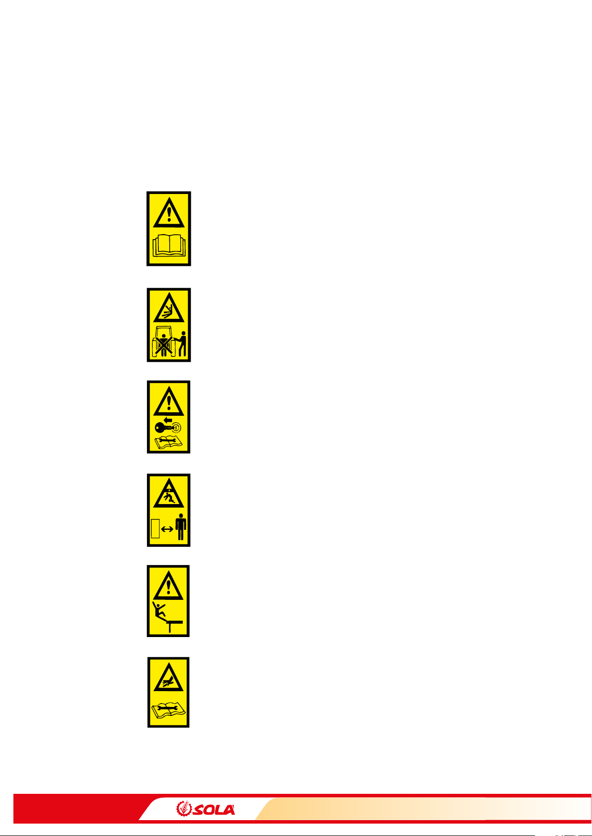
3.1 SAFETY SYMBOLS .................................................................................................................................................... 8
3.2 USE ACCORDING TO DESIGN................................................................................................................................. 9
3.3 GENERAL SAFETY REGULATIONS ...................................................................................................................... 10
3.4 LOADING AND UNLOADING INSTRUCTIONS ................................................................................................... 11
4. ESSENTIAL SOWING CONCEPTS........................................................................................................................ 12
4.1 TERRAIN .................................................................................................................................................................. 12
4.2 SEEDS....................................................................................................................................................................... 12
4.3 SEED PLANTING DEPTH ....................................................................................................................................... 12
5. ESSENTIAL FERTILISING CONCEPTS ................................................................................................................. 14
5.1 FACTORS TO BE TAKEN INTO ACCOUNT FOR A GOOD FERTILISATION ....................................................... 14
6. STARTING .......................................................................................................................................................... 15
6.1 COUPLING THE FRONT HOPPER TO THE TRACTOR ......................................................................................... 15
6.2 CONNECTIONS....................................................................................................................................................... 16
6.3 LOADING THE HOPPER MANUALLY ................................................................................................................... 17
6.4 SUPPORTING LEGS ............................................................................................................................................... 18
7. DOSAGE ............................................................................................................................................................. 19
7.1 SEED / FERTILISER GRAIN OF REGULAR SIZE (POSITION N) ........................................................................... 20
7.2 FINE SEED / FERTILISER GRAIN (MICRODOSING – POSITION F) .................................................................... 20
7.3 CALIBRATION TEST ................................................................................................................................................ 21
7.4 COMPLEMENTARY DOSING TESTS...................................................................................................................... 23
7.4.1 TEST TO DETERMINE THE NUMBER OF WHEEL TURNS. ...................................................................... 23
7.4.2 SEED DOSING ADJUSTMENTS ................................................................................................................. 25
7.4.3 FERTILISER DOSING ADJUSTMENTS....................................................................................................... 27
8. TYPES OF DISTRIBUTION .................................................................................................................................. 29
8.1 FERTILISER DISTRIBUTION BY MECHANICAL FAN .......................................................................................... 29
8.2 FERTILISER DISTRIBUTION BY HYDRAULIC FAN.............................................................................................. 30
9. NEUMASEM ELECTRONICAL CONTROLLER....................................................................................................... 31
9.1 FRONT PANEL DESCRIPTION ............................................................................................................................... 31
9.2 FORWARD SPEED - C1 .......................................................................................................................................... 32
9.3 TOTAL AREA / WORKING WIDTH – C2................................................................................................................ 33
9.4 FAN RPM / FAN ALARMS – C4 .............................................................................................................................. 34
9.5 METERING BOX’S SHAFT RPM– C5 ..................................................................................................................... 35
9.6 HOPPER LOW LEVEL ALARM – C6....................................................................................................................... 36
10. MAINTENANCE ................................................................................................................................................ 37
10.1 CHECKING FREQUENCY...................................................................................................................................... 38
10.2 GREASING AND LUBRICATING.......................................................................................................................... 40
10.3 FANS ...................................................................................................................................................................... 41
10.4 FRONT HOPPER CLEANING................................................................................................................................ 41
11. DOSAGE TABLES .............................................................................................................................................. 42
11.1 SEED MICRODOSING ........................................................................................................................................... 42
11.2 REGULAR SEEDS DOSING................................................................................................................................... 46
11.3 FERTILISER DOSING IN MACHINES EQUIPPED WITH TINE COULTERS ....................................................... 53
11.4 FERTILISER DOSING IN PLANTERS .................................................................................................................... 57
12. WARRANTY...................................................................................................................................................... 62

4
13. SPARE PARTS ................................................................................................................................................... 63
13.1 DISTRIBUTOR........................................................................................................................................................ 64
13.2 MECHANICAL TRANSMITION ............................................................................................................................ 66
13.3 HYDRAULIC FAN .................................................................................................................................................. 68
14. NOTES.............................................................................................................................................................. 71

5
INTRODUCTION
It is essential to read and follow the instructions and recommendations in this manual before operating
the front hopper KIBLI. Careful reading enables maximum operator eciency, prevents accidents
and damage, and increases the front hopper’s capacity and life expectancy.
Please ensure that this manual has been read by any person involved in performing operational tasks,
(including preparation, dealing with mechanical problems and supervising the machine), maintenance
(inspection and technical assistance) and transport.
For your safety, please follow these technical safety instructions as SOLÀ will not be responsible for
damages caused by not observing the information provided.
In the rst chapters you will nd the Technical Characteristics and Safety Instructions. Basic concepts
that are required to operate the machine are explained in the Starting, Adjusting and Maintenance
sections.
The last part of this manual consists of Dosage Tables for seeds and fertiliser.
SOLÀ RETAINS THE RIGHT TO MODIFY ILLUSTRATIONS, TECHNICAL DATA AND WEIGHTS INDICATED
IN THIS OPERATING MANUAL, IF THESE CHANGES HELP TO IMPROVE THE QUALITY OF THE MACHINES.
In this operating manual you will nd three dierent symbols relating to safety:
TO WORK MORE EASILY WITH THE FRONT HOPPER.
TO PREVENT DAMAGE TO THE FRONT HOPPER AND OPTIONAL EQUIPMENT.
TO PREVENT PHYSICAL INJURY.
1. INTRODUCTION

6
TECHNICAL CHARACTERISTICS
2.1 OVERVIEW
2.2 TECHNICAL CHARACTERISTICS
2. TECHNICAL CHARACTERISTICS
CHARACTERISTICS
Hopper capacity (Litres) 2.000
Curb weight (Kg) 850
Full load weight (Kg) 2350
Width (m) 2,55
Length (m) 1,5
Height (m) 1,6
Folding cover
Hopper
Work light
Fan
Platform to gain access
to the hopper
Metering box
Supporting legs
Transmission
starwheel

7
1 2
3
45
TECHNICAL CHARACTERISTICS
2.3 MACHINE IDENTIFICATION
All machines have an IDENTIFICATION PLATE, where the following data is specied:
1- Manufacturer’s name and adress
2- Machine model
3- Machine type
4- Serial number
5- CE certicate
2.4 STANDARD EQUIPMENT
Scales and seed counter.
Folding hydraulic transmission starwheel or electrical transmission.
2000 L Hopper.
Hopper’s folding cover.
Metering box for fertiliser and small or big seeds.
Platform to gain access to the hopper.
Supporting legs.
Front lights.
Sieves in the hopper.
Hydraulical fan.
Sowing electronical controller Neumasem or Artemis Lite.
2.5 OPTIONAL EQUIPMENT
Mechanical fan.

8
SAFETY INSTRUCTIONS
3.1 SAFETY SYMBOLS
On the machine you will nd the following warning pictograms:
READ THE INSTRUCTIONS CAREFULLY AND OBSERVE THE SAFETY ADVICE GIVEN
IN THE OPERATING MANUAL.
DURING THE COUPLING MANOEUVRE, STAY AWAY FROM THE FRONT PART OF
THE TRACTOR. RISK OF SERIOUS PHYSICAL INJURY.
DURING MAINTAINING OR REPAIRING THE MACHINE, YOU MUST STOP THE TRAC
TOR’S ENGINE COMPLETELY AND REMOVE THE IGNITION KEY.
RISK OF BEING CRUSHED WHEN WORKING UNDER THE MACHINE, PLEASE SECURE
THE MACHINE TO PREVENT THIS RISK. RISK OF SERIOUS PHYSICAL INJURIES.
NEVER USE THE LADDER TO ACCESS THE PLATFORM WHEN THE MACHINE IS RUN
NING. IT IS FORBIDDEN TO RIDE ON THE MACHINE DURING OPERATION. RISK OF SE
RIOUS PHYSICAL INJURIES.
DANGER OF INFECTION FROM ESCAPING HYDRAULIC FLUID AT HIGH PRESURE!
THIS CAN INFLICT SERIOUS INJURIES WITH POTENTIALLY FATAL CONSEQUENCES
IF IT PASSES THROUGH THE SKIN AND INTO THE BODY. KEEP THE HOSE LINES IN
GOOD CONDITION. RISK OF SERIOUS PHYSICAL INJURIES.
3. SAFETY INSTRUCTIONS

9
SAFETY INSTRUCTIONS
RISK OF INJURIES TO THE EXTREMITIES BY BEING TRAPPED.
DO NOT EXCEED MAXIMUM LOAD.
COUPLING POINT FOR LOADING AND UNLOADING THE MACHINE BY CRANE.
DO NOT INSERT YOUR HAND INTO THE HOPPER WHILE THE DRIVE WHEEL IS TUR
NING. RISK OF SERIOUS PHYSICAL INJURY.
3.2 USE ACCORDING TO DESIGN
-
The KIBLI front hopper has been specically designed to be used as FRONT DOSING
HOPPER for seeds or fertiliser.
-
If the machine is used in circumstances other than the above, SOLÁ will not be held res-
ponsible for any damage caused (see section 12. WARRANTY)
-
The user must observe all regulations concerning safety, trac and hygiene.
-
If the machine is modied by the user, the manufacturer’s warranty is cancelled. SOLÁ
will not be held responsible for any damage caused (see section 12. WARRANTY).
Kg. Max.

10
SAFETY INSTRUCTIONS
3.3 GENERAL SAFETY REGULATIONS
BEFORE STARTING THE MACHINE, PLEASE CHECK THE MACHINE IS IN GOOD CONDI
TION FOR WORK AND IS SAFE FOR ROAD USE.
BEFORE STARTING THE MACHINE, CHECK THAT VISIBILITY IS CLEAR AROUND THE
MACHINE AND THERE IS NO PERSON IN THE WORKING AREA.
IN THOROUGHFARE, PLEASE OBSERVE TRAFFIC SIGNS AND REGULATIONS.
IT IS FORBIDDEN TO RIDE ON THE MACHINE DURING OPERATION OR TRANSPORT.
RISK OF SERIOUS PHYSICAL INJURIES.
BEFORE USING THE MACHINE, THE USER MUST BE FAMILIAR WITH ALL OPERATING
ELEMENTS.
PLEASE BE EXTREMELY CAREFUL WHEN COUPLING AND UNCOUPLING THE MACHI
NE TO THE TRACTOR.
NEVER LEAVE THE DRIVER SEAT DURING OPERATION.
DO NOT DEPOSIT EXTERNAL ELEMENTS INSIDE THE HOPPER.
WHEN MANTAINING THE HYDRAULIC SYSTEM OF THE FRONT HOPPER, MAKE SURE
THAT IT IS DEPRESSURISED AND THE TRACTOR’S ENGINE IS OFF.
PLEASE REGULARLY CHECK THE CONDITION OF THE TUBES AND HOSEPIPES IN THE
HYDRAULIC SYSTEM. THESE PARTS AGE NATURALLY AND THEIR LIFE SHOULD NOT
SURPASS 6 YEARS. PLEASE REPLACE WHEN NECESSARY.
DURING TRANSIT WITH THE RAISED FRONT HOPPER, BLOCK THE LOWERING SWITCH.
BEFORE LEAVING THE TRACTOR, LOWER THE FRONT HOPPER ONTO THE GROUND
AND REMOVE THE TRACTOR’S STARTING KEY.

11
SAFETY INSTRUCTIONS
PLEASE CHECK THAT THE PTO SHAFT IS IN GOOD CONDITION AND WELL PROTEC
TED. PREVENT THE PROTECTIVE TUBE FROM TURNING BY HOLDING BOTH THE TUBE
AND CHAIN PROVIDED FOR THIS PURPOSE.
ALWAYS USE ENOUGH SUPPORTING ELEMENTS WHEN MAINTAINING THE MACHINE
IN A RAISED POSITION TO PREVENT THE MACHINE FROM LOWERING OR FALLING.
MOUNT THE PTO SHAFT ONLY WHEN THE TRACTOR’S ENGINE IS OFF.
BEFORE CONNECTING THE PTO SHAFT, BE SURE THAT THE DANGER ZONE SURROUN
DING THE MACHINE IS CLEAR.
3.4 LOADING AND UNLOADING INSTRUCTIONS
Loading and unloading the machine must be performed, if possible, using a bridge
crane.
The following pictures show the position of the tow ropes to perform this operation,
going around (surrounding?) the hopper through the inside part of the frame. A di-
erent way of doing it is by using the three-point linkage (in this case, see chapter 6.1
COUPLING THE FRONT HOPPER TO THE TRACTOR).
To know the total weight that the bridge crane will need to bear, see section 2.2 TECH-
NICAL CHARACTERISTICS.
THESE OPERATIONS SHOULD BE PERFORMED
ONLY BY QUALIFIED AND EXPERIENCED PER-
SONNEL.

12
ESSENTIAL SOWING CONCEPTS
4. ESSENTIAL SOWING CONCEPTS
WHEN STARTING THE MACHINE, FURROWS WILL NOT CONTAIN ANY SEEDS FOR A METRE.
WHEN STOPPING THE MACHINE, SEEDS WHICH WERE PREVIOUSLY INSIDE THE SEED HO-
SES, SLIDE FROM THE MACHINE AND END UP PILED ON THE GROUND. TAKE THIS INTO
ACCOUNT WHEN STOPPING AND STARTING THE MACHINE IN ORDER TO ACHIEVE MORE
ACCURACY.
ALWAYS WORK AT A UNIFORM SPEED AS SUDDEN ACCELERATING AND SLOWING DOWN
WILL CAUSE AN IRREGULAR SEED DISTRIBUTION.
4.1 TERRAIN
The better the soil condition, the better the sowing quality. Work is more dicult on big
clods or uneven furrows. Although SOLÀ machines resist harsh conditions, if the seedbed
does not satisfy appropriate conditions then the sowing quality will suer.
4.2 THE SEED
It is essential that seeds are well maintained and clean. Barley seeds should be trim-
med.
4.3 SEED PLANTING DEPTH
THE RECOMMENDED SEED PLANTING DEPTHS ARE FROM 3 TO 5 CENTIMETRES. PLAN-
TING TOO DEEP CAUSES PROBLEMS AS RHIZOME CANNOT REACH THE SURFACE AND THE
PLANT WILL DIE. IT DOES NOT MATTER THAT SOME GRAINS ARE VISIBLE BECAUSE THE
HARROW’S TINES WILL COVER THEM EVENTUALLY.
The seed planting depth has consequences for tillering, as well as for the plant’s strength
and its ability to resist frostbite or drought. The parent shoot grows from 1 to 2 cm under
the ground, whatever the depth of the seed.
Planting deeper does not necessarily mean getting deeper roots. Only a few roots grow
from the lower part of the seed. Most of them grow from a parent shoot close to ground
level.

13
ESSENTIAL SOWING CONCEPTS
NORMAL PLANTING DEPTH: FROM 2 TO 4 CM
- Thick stem, short rhizome, resistant to frostbite
- Multiple tillering providing from 3 to 6 shoots and a lot of blades, from 6 to 10.
- Deep and thick roots, approximately 5 cm in width and 10-12 cm in depth.
- With less grains per sowing square metre, more ears are obtained.
DEEPER PLANTING: FROM 5 TO 6 CM
- Fine stem, rhizome exposed to frostbite.
- Late and weak tillering, 1 or zero shoots and only a few blades, 3-4 aprox.
- Medium quality roots of approximately 3 cm in width and 5 cm in depth
-
More grains per sowing square metre are required to obtain the same number of ears as
in the previous case.
VERY DEEP PLANTING: FROM 8 TO 10 CM
- Very ne stem. No tillering and only one blade.
- Seed runs out of supplies by growing a long rhizome which frostbite can easily cut.
- The plant takes weak roots, approximately 1 cm in width and 3 cm in depth.
-
Twice the number of grains per sowing metre are required to obtain the same number
of ears as in the rst case.
IN VERY COLD PLACES, REPEATED FROSTBITE CAN HAVE A HONEYCOMB EFFECT ON THE
GROUND’S MOST SUPERFICIAL LAYER. IN THIS CASE THE PLANT’S VERY FIRST ROOTS CAN
LOOSEN AND THE PLANT WILL DIE. SLIGHTLY DEEPER PLANTING IS RECOMMENDED AND
IF POSSIBLE, THE USE OF ROLLERS TO COMPACT THE EARTH TO BETTER PROTECT THE
SEEDS.
Seed
Seed
Seed

14
ESSENTIAL FERTILISING CONCEPTS
THE FRONT HOPPER SHOULD BE WELL WASHED AFTER THE WORK (SEE SECTION 10.4
FRONT HOPPER CLEANING). OTHERWISE THE FERTILISER REMAINING IN THE MACHINE
COULD CORRODE AND DAMAGE IT
5.1 FACTORS TO BE TAKEN INTO ACCOUNT FOR A GOOD FERTILISATION
1- Forward speed:
To obtain a uniform fertilisation, keep the forward speed without sudden stops, since
variations in forward speed modify the amount of fertiliser applied on the ground.
When starting and stopping, take into account the way in which the air circuit works. This
circuit carries the fertiliser from the metering box to the metering units or to the coulters,
and works as follows:
-
When STARTING, the circuit is empty and the machine will not fertilise until it has
run some metres.
-
When STOPPING, the circuit is FULL of fertiliser. It is recommended to cut the fer-
tilisation by raising the machine or by lifting the transmission starwheel a couple
metres before stopping.
2- Check fertiliser’s ow:
Perform a previous calibration test in the warehouse in order to know exactly the amount
of fertiliser going to be spread. Dosage is going to be very dierent when using dierent
kinds of fertiliser, as it depends on factors such as density, moisture content, etc..
3- Distance between tramlines:
Keeping the distance between tramlines is essential to get optimal fertilisation.
5. ESSENTIAL FERTILISING CONCEPTS

15
1
2
3
4
5
STARTING
6.1 COUPLING THE FRONT HOPPER TO THE TRACTOR
The front hopper KIBLI is equipped with a three-point linkage of cathegory 3.
To couple the hopper to the tractor, follow these steps:
1- Fix the three-point linkage to the tractor using 3 bolts (1).
2- Loosen the screw (2) in order to free the hopper’s safety lock (3).
3- Introduce the three-point linkage to the front hopper.
4- Make sure the trigger of the three-point linkage (4) has been correctly inserted.
5- Adjust the safety lock (3) using the screw (2).
To remove the three-point linkage from the hopper:
1- Uncouple the three-point linkage from the tractor by unscrewing the 3 bolts (1).
2- Loosen the screw (2) in order to free the hopper’s safety lock (3).
3- Raise the hopper slightly (it must be in contact with the ground) and pull the lever
(5) in order to free the three-point linkage from the hopper. Make sure that the
trigger (4) is not locked.
6. STARTING

16
Fig. 9
Fig. 10
Fig. 9
Fig. 10
Fig. 9
Fig. 10
ESSENTIAL FERTILISING CONCEPTS
TO PERFORM THIS OPERATION, THE FRONT HOPPER’S WHEELS MUST BE BRAKED
WHILE PERFORMING THE COUPLING AND UNCOUPLING OPERATIONS, MAKE SURE
THERE IS NO PERSON OR OBJECT BETWEEN THE TRACTOR AND THE FRONT HOPPER.
6.2 CONNECTIONS
Connect the ELECTRIC plug for the machine’s FRONT LIGHTS.
The front hopper is equipped with the following HYDRAULIC connections:
To raise and lower the transmission starwheel:
- a single-acting connection.
If the machine is equipped with HYDRAULIC FAN:
- one single-acting connection and a free return line.
If the machine is equipped with a COOLING SYSTEM FOR THE MECHANICAL FAN:
- a double-acting connection.
If the machine model is equipped with a MECHANICAL FAN, the PTO shaft should be
adapted:
1- Dismount the PTO shaft and insert one end into the tractor’s universal
joint shaft and the other end into the front hopper. Look for the minimal
movement length “L” by raising and lowering the hydraulic lift.
2- Cut the spare plastic and metal into parts of the same length and re-
mount the PTO shaft.
3- Operate the hydraulic lift and check that the PTO shaft’s movement is
correct.
4- Fix the PTO-shaft to the tractor using the securing chain.

17
1
3
2
ESSENTIAL FERTILISING CONCEPTS
WHEN OPERATING THE PTO SHAFT CHECK THAT THE ENGINE IS OFF. ALWAYS WORK WITH
THE PTO SHAFT PROTECTED AND IN GOOD CONDITION. PREVENT THE PTO SHAFT’S TUBE
FROM TURNING BY SECURING IT WITH THE CHAIN PROVIDED.
WHEN LOWERING THE FRONT HOPPER TO THE GROUND, UNPLUG THE TRACTOR’S UNI-
VERSAL JOINT SHAFT SO THAT THE PTO SHAFT DOES NOT HAVE AN EXCESSIVE INCLINA-
TION (MAX. 35º).
WHEN HOLDING THE TRACTOR UNIVERSAL JOINT SHAFT’S CLUTCH IN, PERFORM IT GENT-
LY. STARTING SUDDENLY COULD SERIOUSLY DAMAGE THE MACHINE.
6.3 LOADING THE HOPPER MANUALLY
For access to the hopper, follow these steps:
1-
Pull the safety trigger (1) to free the hopper’s platform. Next,
pull the platform untill it is horizontal. To fold it, pull the safety
trigger (1) and pull the platform upwards until it is locked with
the trigger.
2-
Pull to remove the elastic strap (2) that secures the hopper’s fol-
ding cover.
3-
At the sides of the hopper, there are handles. Use them to push
forward and fold the cover over

18
ESSENTIAL FERTILISING CONCEPTS
4-
Fill the machine with seeds or fertiliser without removing the
sieves. Gaining access to the hopper to ll it manually is an easy
operation. However, in order to ll the hopper in a quick and
safe way, it is recommended to use a BIG BAG along with an
approved small crane.
5-
After lling the hopper, fold the cover back, place the elastic
straps (2) and use the trigger to secure the platform (1).
6.4 SUPPORTING LEGS
The front hopper KIBLI is equipped with 4 supporting legs. This legs are wheels to load
and unload the machine, so that transporting the machine becomes easier.
TWO OF THESE WHEELS HAVE A FOOT BRAKE TO BE USED WHEN STORING THE MACHINE
OR WHEN TRANSPORTING IT ON A TRAILER.

19
2
63
5
4
1
DOSAGE
To gain access to the dosing system, the platform has to be unfolded (see point 1 from
seccion 6.3 LOADING THE HOPPER MANUALLY).
There are two ways of dosing:
for regular seeds
for ne seeds with minimum ow rate
WHILE THE MACHINE IS WORKING, THE HANDLE OF THE VENTURI INJECTOR SLUICE
MUST BE ALWAYS IN POSITION “OK”. IT MUST BE IN POSITION “NO” ONLY FOR THE
CALIBRATION TEST.
7. DOSAGE
COMPONENT
1Venturi injector sluice
2Dosing graduated scale
3Bolt
N=regular seed
F=ne or small seed
4Spindle
5Trap-door to quickly empty the
hopper and the metering box.
6Button for the calibration test

20
4
1
4
N
N
F
1
3
4
F
N
F
DOSAGE
7.1 SEED / FERTILISER GRAIN OF REGULAR SIZE (POSITION N)
Proceed as follows to adjust the dosing for SEEDS or FERTILI-
SER or REGULAR size:
1-
Pull and turn the spindle (4) to adjust the graduated scale
(to adjust the dose see section 11 – DOSAGE TABLES).
2- Place the pinions in position N (in red).
3- Place the clip pin of the air outlet to fan at position N.
7.2 SEED / FERTILISER OF SMALL SIZE (POSITION F)
IN ORDER TO CHANGE THE PIN’S POSITION (3),
IT IS ESSENTIAL THAT THE SPINDLE (4) OF THE
METERING BOX CAN TURN FREELY AND THE HO-
PPER IS EMPTY.
Proceed as follows to adjust the dosing for SEEDS or FERTILI-
SER or SMALL size:
1- Turn the spindle (4) until it reaches position 0 on the gra-
duated scale (1).
2- Remove the clip pin (3) and place it in position MICRO (F).
3-
Turn the spindle (4) to adjust the graduated scale be-
tween 0 and 30 (to adjust the dose, see section 11- DO-
SAGE TABLES) .
4- Place the pinions in position N (in red).
5-
Congure the ELECTRONICAL CONTROLLER (see section
9. ELECTRONICAL CONTROLLER, working in micro mode).
THE AIM OF MICRODOSING IS TO BETTER DISTRIBUTE FINE SEEDS, OR REGULAR SEEDS IN SMALL NUMBERS.
CHECK THE CLEANING BRUSH IS IN GOOD CONDITION BEFORE STARTING WORK.
WHEN MICRODOSING FINE SEEDS, DO NOT EXCEED NUMBER 30 ON THE GRADUATED
SCALE (2) (SEE SECTION 11. DOSAGE TABLES).
Table of contents
Other Sola Farm Equipment manuals
Popular Farm Equipment manuals by other brands

Land Pride
Land Pride SA10 Operator's manual

LOFTNESS
LOFTNESS 61G4 Series Owner's manual and parts book

burchland
burchland LGX Operator's manual

Krone
Krone Big Pack 890 Original operating instructions

McGREGOR
McGREGOR Agile 4250 Operation & maintenance manual

CrustBuster
CrustBuster Speed King owner's manual

GREAT PLAINS
GREAT PLAINS 3P500 Operator's manual

Pottinger
Pottinger LION 5000 Operator's manual

Bestway
Bestway Field Pro II 1000 Operator's manual

Degelman
Degelman Pro-Till 33 Operator's & parts manual

CSS
CSS MLGFM2000-2400 Assembling Instruction & Part List

Curtis
Curtis Kubota L47 TLB Cab Installation & owner's manual