Sola SV-5 How to use

fertilizer spreader
SV-5
please read carefully prior to operation!
STARTING
MAINTENANCE
DOSAGE

-1-
4ª Edition - 11-2011-
It is forbiden the total and partial reproduction.
We can modify the specifications without prior notice.

Seed Drills and Fertilizer Spreaders SOLÀ are produced in a factory particu-
larly specialized in this kind of machines and they are guaranted for the ex-
perience of the users.
The are machines based on state-of-the art technology and are manu-
factured with recognized safety requirements for doing an excellent work
with a minimal maintenance.
The purpose of this operating manual is to enable you to familiarise
yourself with the working of your seed drill and to achieve your purposes.
-2-

TABLE OF CONTENTS
1. INTRODUCTION .................................................................................4
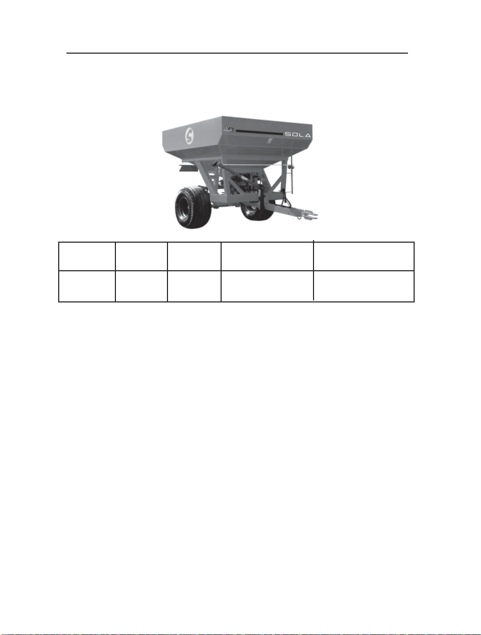
2. TECHNICAL SPECIFICATIONS .........................................................5
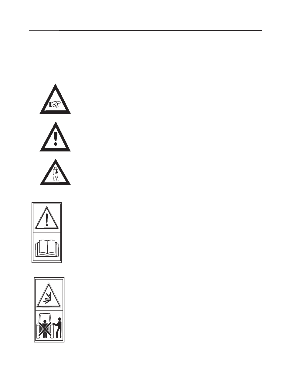
3. SAFETY INSTRUCTIONS ...................................................................6
3.1 Safety symbols ..................................................................................6
3.2 Proper use .........................................................................................8
3.3 General specifications .......................................................................8
4. ESSENTIAL CONCEPTS FOR FERTILIZING....................................10
5. FERTILIZER SPREADER SETTINGS ...............................................11
5.1 Shorten method ................................................................................11
5.2 Physical knowledge of the fertilizer...................................................12
5.3 Working width settings......................................................................13
5.4 Flow setting ......................................................................................15
6. BORDER FERTILIZED ......................................................................17
7. FLOW TEST............... .......................................................................18
8. CARE AND MAINTENANCE..............................................................19
9. DOSAGE TABLES..............................................................................20
10.SPARE PARTS..................................................................................24
10.1 TRANSMISION UNIT......................................................................25
10.2 SHAKER..........................................................................................26
10.3 REAR PROTECTION......................................................................27
10.4 TRANSMISSION PROTECTION....................................................28
10.5 GRADATION UNIT.........................................................................29
10.6 DRIER.............................................................................................30
10.7 COMPLETE MACHINE...................................................................31
10.8 HYDRAULIC EQUIPMENT OPENING AND CLOSING..................32
10.9 BRAKE UNIT...................................................................................33
10.10 ELECTRONIC EQUIPMENT.........................................................34
10.11 DISTRIBUTION EQUIPMENT.......................................................35
-3-
INDEX

Before you proceed to operate the fertilizer spreader, please read and
observe these instructions. In this way, you will avoid accidents, redu-
ce repair costs and downtimes and increase the reliability and service
life of your fertilizer spreader.
This operating manual must be read and used by all persons who are
required to work with the fertilizer spreader (including preparatory work,
troubleshooting during operation, care), maintenance (inspection and
technical servicing) and transporting.
Pay particular attention to the safety instructions. SOLÀ cannot
assume any liability for damage or malfunctions caused by a failure
to observe the instructions contained in this operating manual.
First of all, the manual will explain the Technical Specifications, the
Safety Instructions, and some Essential Concepts for fertilizing.
In the chapters Border Fertilized, Flow Test and Maintenance, the
manual will explain the basic instructions for working with the machine.
This manual is finished with a Dosage Table with different types of
fertilizers.
INTRODUCTION
-4-
SOLÀ reserves the right to make changes to the illus-
trations, technical specifications and weights contained
in this operating manual if SOLA makes any improve-
ments to the fertilizer spreaders.
1.INTRODUCTION

2.TECHNICALSPECIFICATIONS
FERTILIZER SPREADER SV-5
Type Litres Height Hopper sizes Wheels
SV-5 4500 2300 2600x2300 500-50-17/14PR
STANDARD EQUIPMENT
- Distributor group oil-immersed
- Double stainless-steel discs
- Hydraulic brake (service) and mechanical brake (parking)
- Selector sieve of 1,5 m x 1,5 m
- Set of lights (range light, winking light, stoplight)
- Support
- Opening-closing hydraulic control
- Service stair
-5-
OPTIONAL EQUIPMENTS
- Homocinetic power point
- Sieve with access door
- Hydraulic engine Kit
- Cover
TECHNICALSPECIFICATIONS

SAFETYINSTRUCTIONS
3.SAFETYINSTRUCTIONS
3.1 SAFETY SYMBOLS
You will find, in this operating manual, three types of safety and danger symbols:
To facilitate operation with the fertilizer spreader.
On the machine, you will find the following symbols:
Please, read all the
safety instructions
contained in this
operation manual
with care and also
observe all warning
signs attached to
the fertilizer spreader.
Stay away of the
tractor back part
during the coupling
operation, during
the coupling ma-
noeuvre.
Danger of serious
lesions.
-6-
This symbol warns of the risk of injury.
To avoid damages on the fertilizer spreader or in the equipments.

If you are working
under the machi-
ne it is very impor-
tant to assure it
to avoid its
collapse.
Danger of
serious lesions.
Stay away
of the fertilizer
spreader.
Fertilizer grains
impact can cause
a serious lesions.
Danger of se-
rious lesions
caused by the
discs and
spreader
blades.
Direction and
speed of the
power point.
Coupling point for
the transport
by crane.
-7-
SAFETY INSTRUCTIONS
Stop the tractor
engine and avoid
its start during
the maintenance
or repairing works
in the fertilizer
spreader. Consult
the operating manual.
-7-

3.2 PROPER USE
- Fertilizer spreader SOLÀ SV-5 has been produced for the agricultural works
specially for fertilizer with mineral products.
- SOLÀ cannot be held liable for any consequential damage resulting from
incorrect use, metering or distributions.
- All relevant accident prevention regulations, as well as other generally acknow-
ledged safety and road traffic regulations, must be observed.
- SOLÀ fertilizer spreaders are intended for fertilizing. Any uses or modifications
other than those will automatically exempt SOLÀ from its/his liability in respect on
ensuing damages.
3.3 GENERAL SAFETY ARRANGEMENTS
- Before starting the machine, it is very important to read the operation safety and
road safety.
- Road traffic regulations must be observed when towing the machine on roads.
- Before to bring into operation the machine, it is very important to know the parts
and the elements.
- Be extremely careful when coupling and uncoupling the fertilizer spreader to
the tractor.
- The transmission of the power take-off must be fitted with a protective equip-
ment and in good conditions. Avoid the turns of the protector tube with the chain.
The side of the clutch will be fitted in the fertilizer spreader.
- The transmission of the power take-off must be fitted when the engine is stopped.
-Before to connect the power take-off, make sure that nobody is standing in dange-
rous proximity to the fertilizer spreader.
- It is forbidden to stay near of the spreader discs when the machine is starting.
- The fertilizer spreader hopper must be filled when the machine is in the ground,
with the engine stopped and the fertilizer trap devices closed.
SAFETY INSTRUCTIONS
-8-

- Do not place strange elements inside the hopper.
- Always, connect the power take-off with the shaft in order to protect the
fertilizer spreader and to avoid serious damages.
- It is forbidden to ride to the fertilizer spreader during the transport or during
the work.
- Be extremely careful during maintenance works under the machine. It is very
important to use support elements to avoid a possible descent of the machine.
- Before starting, verify the visibility around the machine. It is very important veri-
fy that nobody is standing at the working area.
- Before working on hydraulic system, always de-pressurize the circuit and
switch off the engine.
- The hydraulic system generates extremely high pressures. All piping,
hoses and connections must therefore be checked regularly for leakage and
visible external damage. Useful life for these elements is not more than six
years. You must change them after this time.
- When the fertilizer spreader is full and we have to transport the machine during
a long distance, the fertilizer can compress at the bottom of the hopper. In this
case, the fertilizer exit devices, are blocked.
We will open the exit devices, we will start slowly the power take-off and we will
wait the fertilizer falls. After the operation, we can place the adjustable levers in
the position concerning the chosen flow and we will start to the normal work.
-9-
SAFETYINSTRUCTIONS

-10-
ESSENTIAL CONCEPTS
4. ESSENTIAL CONCEPTS FOR FERTILIZING
1. FERTILIZER GRANULOMETRY: fertilizer with irregular sizes must be refu-
sed in order to avoid an incorrect distribution.
2. P.T.O. SPEED:
The P.T.O. speed determines the speed turn discs. Working width will
change if the speed is modified. Speed must be at 540 rpm.
3. WORKING SPEED:
Strong changes in working speed can modify the fertilizer quantity. Speed
must be steady.
4. HOPPER POSITION:
Hopper position must be horizontal. Lateral movements, forwards and
backwards can modify the fertilizer distribution.
5. WORKING HEIGHT: working height must be uniform to 75 cm from the
ground. Verify the height on the working ground, never in the moment to
coupling the machine. Height could be different.
6. DO NOT FERTILIZER IF IT IS WINDY:
The wind modifies the fertilizer grains trajectory and their distribution.
7. WEAR OF THE DISCS AND BLADES: discs and blades are essential
elements in the fertilizer spreader distribution. Their wear can influence
in the fertilizer distribution. It is necessary to have them in good conditions.
8. VERIFY THE FERTILIZER FLOW:
it is very important to realise a previous test in the store to know the fertilizer
we are going to spread on the land. The dosage is very variable and it depends
on the fertilizer type, density, humidity, etc.
9. DISTANCE BETWEEN ADJACENT RUNS: to conserve the distance between
runs it is very important to have a good distribution. To know the same distance,
follow the adjustment instructions as you can see in the manual. For having
more precision, you can do a test in the land with some boxes placed on the
ground, verifying the fertilizer quantity collected in each box.

-11-
5.1 METHOD FOR FERTILIZER SPREADER SETTING
5.SETTINGOFTHE FERTILIZER SPREADER
ADJUSTMENTS
Basic process to adjust the fertilizer spreader is:
1. To know the fertilizer type, granulometry, density, grains specifi-
cations, for comparing it with another fertilizer type places in this
manual.
2. To know the distribution dose (kg/ha) we are going to spread,
depending of the land, soil and fertilizer type.
3. Verify the dosage tables and choose the correct flow in the
ruled column kg/ha according to the working speed. Adjust the
flow controls as we can see in the tables.
4. To realise a flow test to verify the correct distribution.
.
5. To fertilize in a little and knew land in order to verify the correct
distribution of the fertilizer.

-12-
ADJUSTMENTS
5.2 PHYSICAL KNOWLEDGE OF FERTILIZER
The distribution of the fertilizer spreader changes a lot if the fertili-
zer conditions are different.
Il will be necessary, for each fertilizer type, a different adjusment of
the fertilizer spreader.
The physical attributes of the fertilizer are:
density and granulometry
DENSITY: it is the weight per volume unity and generally it is measu-
red in kg/dm3. It can change depending on the fertilizer humidity.
We are going to compare the fertilizer density to use with another
fertilizer we can see in the dosage tables.
GRANULOMETRY: the granulometry informs us about the sizes of
the fertilizer grains. In the dosage tables we can see the granulome-
try of each fertilizer assembling the grains diameter in four groups:
Ø 4,75 % grains more than 4,75 mm diameter
Ø 3,3 % grains between 3,3 mm and 4,75 mm diameter
Ø 2 % grains between 2 mm and 3,3 mm diameter
Ø <2 % grains < 2 mm diameter
For convention, the fraction containing more than 50% determines
the fertilizer classification. To consider if a fertilizer is correct, the
90% of the gramulometry sizes have to be, at the most, in three
contiguous groups.
We can verify the fertilizer granulometry through the boxes with
homologate sieves.
With this information we can compare the fertilizer to spread with
another placed in the dosage tables.

-13-
5.3 SETTING OF THE WORKING WIDTH
Observing dosage tables we can see that for a same type of fertilizer,
the blades position on the disc changes depending on the working
width and the dose to spread.
Fitted on each disc we have two different blades: one blade called "short"
and the other blade called "long".
The short blade position is indicated by one or two letters (X
- A - B) and a number (1 - 2 - 3). When the letter X is not indicated, the
blade will be fitted in the hole without mark.
Long blade is indicated by a letter (C - D - E) and a number
(4 - 5).
The letters (A - B - C - D - E) inform us about the bolt position
concerning the blade, as we can see in the drawing.
The letter X and the numbers (1 - 2 - 3 - 4 - 5) inform us about the
blade position on different holes of each disc as we can see in the
drawing.
ADJUSTMENTS

-14-
ADJUSTMENTS
Find as follows an exemple: we want to fertilize with nitrate NAC 26%
as we can find on the dosage table (page 21). We need a dose of
150 kg/ha, a working width from 18 m and a working speed of
8 km/h.
We verify in the column of 18 m working width and 8 km/h of
working speed the flow case that inform us the nearest value
(in this case 158 kg/ha) to the looked forward dose. In the position
column of the blades concerning this value we can see the positions
XB2 and C4.
The first position refers to the short blade. We have place it in the
position B and in the holes X and 2 of the disc. The other position refers
to the long blade. We place it in the position C, hole 4 of the
disc.
Both discs have always to be placed with the blades in the same positions.

-15-
ADJUSTMENTS
5.4 FLOW SETTING
When we known the fertilizer specifications, we look for the dosage
table the fertilizer more similar to the fertilizer we are going to use.
As we know the dose we need
and also the working width,
we look for the case about
the correct dose (kg/ha)
in the column concerning
to the working width and
to the working speed.
When we have the correct
dose, we go by the same
row until the column on the
left of the table, where we
are going to read the posi-
tion of the adjustment lever.
For exemple, we are going to continue on the case of page 14:
we want to fertilize with nitrate NAC 26% to 150 kg/ha and speed 8 km/h,
working width 18 m.
We look for on the column of 18m working width and 8 km/h speed
the case refers 150 kg/ha. On the left column of the table we read
the position of the adjustment lever: 7.

-16-
ADJUSTMENTS
When we give pressure to the cylinder release, the fertilizer exit devi-
ces close (lever 1 goes to zero). When we eliminate pressure, the
cylinders return to the pre-established position with the selection
check and open the exit devices with the flow required.
By means of two control valves we can choose one of the following
options:
zAll machine, that is, two disc are working at the same
time. (Two valves have to be open)
zHalf right (only a disc - only a valve is open)
zHalf left (only a disc - only a valve is open)
If we want to work only with half machine, it is necessary to give
pressure to the cylinders, and then, to close the control valve
we want put out of action.
During the long displacements with the fertilizer spreader well full, it is
necessary, one time closed fertilizer exit devices, to close two
valves to avoid the fertilizer leakage by fertilizer exit devices.

FERTILISED
-17-
6. EDGES FERTILISED
Fertilised distribution in the limit of the land.
For fertilizing the land edges it is necessary to start the work just in
the land limit, closing the fertilizer exit device concerning to the limit
side. We can do this operation, working the hydraulic control valves
in the way we have seen in the previous page.

FLOWTEST
-18-
7. FLOW TEST
To know the fertilizer flow, spreaded by the fertilizer spreader, we
will do a test. We will control the quantity comes out by a fertilizer exit
device during a minute (we have this information on the dosage tables.
Pages 21 to 23). When the flow will be fixed, the quantity to spread
per hectare will depend only on working speed and the runs
width.
Find as follows the points for doing the test:
zDetach to the right disc
zPlace a container under the hopper exit device to
collect the fertilizer.
zTurn the power take-off to 540 r.p.m.
zPlace the adjuster stop in the correct position.
zOpen the right side fertilizer exit device during a minute.
zW Weight the collected fertiizer (we will obtain kg/min).
Para obtener el caudal en kg/ha aplicaremos la siguiente fórmula:
Verify the adjuster and repeat these operations for obtaining the flow
desired.
1200 x flow (kg/min)
speed (km/h) x working width (m)
DOSE (kg/ha) =

GREASINGAND MAINTENANCE
-19-
zEvery day, the shaft of the power take-off must be
libricated with grease.
zThe gear box are greased with type NLGI 00
(lithium grease EP 00). Verify very often the level
Verify often tne level of the grease.
zLubricate with oil the articulations of the levers and
joints.
zIt is necessary to wash the fertilizer spreader with
water after use it.
zIf the fertilizer spreader must be stocked during a long
time, it is necessary to protect the machine with pro-
tective coverings (oil, corrosion inhibitor).
8. GREASING AND MAINTENANCE
Table of contents
Other Sola Farm Equipment manuals
Popular Farm Equipment manuals by other brands

Krone
Krone EasyCut B 870 CR operating instructions

GREAT PLAINS
GREAT PLAINS Ultra Chisel 6000 Series Predelivery Manual

UNIA
UNIA HARRIER Operating and maintenance manual

Duncan
Duncan Renovator AS3000 owner's manual

Wessex
Wessex RC 190 Operations manual and parts book

horsch
horsch Maestro SW Series owner's manual