SOLTEK KT400 User manual

4
KT400
Contents
Chapter 1 Specification ............................................. 8
1-1 KT400 Mainboard Layout ......................................................9
1-2 Mainboard Specifications .................................................... 10
1-2.1 CPU Socket ................................................................................... 10
1-2.2 Syste Chipsets ........................................................................... 10
1-2.3 Me ory ......................................................................................... 10
1-2.4 BIOS............................................................................................... 10
1-2.5 Accelerated Graphics Port (AGP) Interface........................... 10
1-2.6 Advanced Syste Power Manage ent .................................... 11
1-2.7 Multi-I/O Functions .................................................................... 11
1-2.8 Expansion Slots ............................................................................ 11
1-2.9 AC’97 Audio Codec on board .................................................... 12
1-2.10 Hardware Monitor on board ................................................... 12
1-2.11 S art Card Reader Support ................................................... 12
1-2.12 For Factor................................................................................ 12
1-3 Mainboard Specification Table ........................................... 13
1-4 Chipset Syste Block Diagra ........................................... 14
Chapter 2 Hardware Setup ..................................... 16
2-1 CPU Identification and Installation ................................... 17
2-1.1 CPU Identification Legends....................................................... 17
2-1.2 CPU Installation with Socket 462 ............................................. 18
2-2 Me ory Installation ............................................................. 19
2-2.1 To Install DDR SDRAM Module .............................................. 19
2-2.2 To Re ove a DIMM .................................................................... 19
2-2.3 Warning Indicator LED1: DIMM Slots Powered On ........... 20
2-3 AGP Slot Installation ............................................................ 21
2-4 IDE Connector Installation ................................................. 22

5
Contents
2-5 Floppy Drive Connector ( FDC ) Installation................... 23
2-6 ATX Power Supply Installation .......................................... 24
2-7 Ju per Settings ..................................................................... 25
2-7.1 How to tackle the Ju pers: ....................................................... 26
2-7.2 JCLK1: CPU Clock/Overclock Select...................................... 26
2-7.3 JBAT1: Clear CMOS .................................................................. 27
2-7.4 Jp1: Anti-burn Shield (ABSII) .................................................. 28
2-7.5 Jp3: PS2 KB/Mouse Wake-up ................................................... 29
2-7.6 Jp4: USB KB/Mouse Wake-up .................................................. 29
2-8 Other Connectors Configuration........................................ 30
2-8.1 On-board FAN Connectors ........................................................ 30
2-8.2 USB Ports and USB Pin-headers .............................................. 31
2-8.3 Chassis Panel Connectors .......................................................... 32
2-8.4 PS/2 Mouse And PS/2 Keyboard ............................................... 32
2-8.5 CD-ROM Audio Connectors (CD-In1) .................................... 33
2-8.6 S art Card Reader Connector: SCR1 .................................... 33
2-8.7 Connector WOL1: Wake On LAN............................................ 34
2-8.8 Ther al Connectors.................................................................... 35
2-8.9 Co plex Pin-header (Front Panel Connectors) ..................... 36
2-8.10 Audio 1: 6-channel Sound Output Connector (optional) ...38
2-9 IRQ Description..................................................................... 39
Chapter 3 Software Setup ....................................... 40
3-1 Open Up Support CD: .......................................................... 41
3-2 Proceed to VIA 4-IN-1 Drivers Installation ...................... 42
3-3 AC’97 Audio Driver Installation......................................... 44
3-3.1 AC’97 Driver Installation........................................................... 44
3-3.2 6-channel Verification ................................................................. 45
3-4 Install USB 2.0 Driver for Win98 / Me / 2000 / XP.......... 48
3-5 Install Hardware Monitor Utility ....................................... 50
3-5.1 Installation ................................................................................... 50
3-5.2 Verification .................................................................................. 51

6
KT400
Chapter 4 AMI BIOS Setup.................................... 52
4-1 About BIOS Setup ................................................................. 53
4-2 To Run BIOS Setup ............................................................... 53
4-3 About CMOS .......................................................................... 53
4-4 The POST ( Power On Self Test ) ....................................... 53
4-5 To Update BIOS ..................................................................... 54
4-6 BIOS SETUP --- CMOS Setup Utility................................ 56
4-6.1 CMOS Setup Utility .................................................................... 56
4-6.2 Standard CMOS Setup ............................................................... 57
4-6.3 Advanced BIOS Features ........................................................... 60
4-6.4 Advanced Chipset Features ....................................................... 63
4-6.5 Power Manage ent Features .................................................... 66
4-6.6 PNP / PCI Configurations .......................................................... 69
4-6.7 Integrated Peripherals................................................................ 71
4-6.8 S artDoc Anti-Burn Shield....................................................... 74
4-6.9 Frequency/Voltage Control ....................................................... 76
4-6.10 Syste Infor ation................................................................... 78
4-6.11 Set Supervisor Password .......................................................... 79
4-6.12 Load Opti ized Defaults ........................................................ 81
4-6.13 Save & Exit Setup...................................................................... 81
4-6.14 Exit Without Saving .................................................................. 81
APPENDICES.......................................................... 82
Appendix-1 Identify Mainboard Model Nu ber ................... 83
Appendix-2 Technical Ter s ...................................................... 84

7
Contents
Mainboard
Support CD
Bundled Bonus Pack CD
Bundled Bonus Pack Manual
Thermal Cable (Optional)
ATA66/100/133 IDE Cable
FDD Cable
User Manual
Multi-lingual Quick Installation Guide
RS232 Cable (Optional)
ITEM CHECKUP

8
KT400
Topics incl ded in this chapter are:
1-1 Mainboard Layo t
1-2 Mainboard Specifications**
1-3 Mainboard Specification Table
1-4 Chipset System Block Diagram
Introd ction
Chapter 1 Specification
This mainboard features an integration of the powerful AMD proces-
sors Athlon/Athlon XP/Duron and the North Bridge VIA Apollo KT400
plus South Bridge VT8235, with which the whole system performance
supports 333/266/200 MHz system bus.
VIA Apollo KT400 plus VT8235 supports on-board AMD processors
to implement the 333/266/200MHz Front Side Bus, the AGP 8X/4X
interface, the LPC Super I/O, the DDR *400/333 MHz SDRAM, the 6-
channel AC’97 Audio interface, the USB 2.0 interface and ATA 133/100/
66 data transfer rate. This chapter is to introduce to users every ad-
vanced function of this high performance integration.
** If any difference is fo nd between the man al description
and the Mainboard yo are sing, please look p the Errata/
Update Slip enclosed inside for the correction or pdated
information, or else contact the Mainboard Dealer or visit o r
Web Site for the latest man al pdate.

9
Chapter 1 Specification
PCI1
PCI2
PCI3
PCI4
PCI5
VIA
KT400
DIMM1
IDE2
IDE1
Li
Battery
Fan4
1
1
Fan3
Fan5
1
VIA
VT8235
Flash BI S
IT8705
AC'97
Codec
W L1
1
AGP 4X/8X
Clock
Generator
SPK RST PLED Keylock SLED
HDD/LED IR PWR SMI
++
--
+-
1
USB2
1
10
RT2
PCI6
Audio1
14
SCR1 14
1
USB1
1
10
Fan1
FDC
1
DIMM2
LED1
ATX Main Power
1
JBAT1
1
USB1
PS/2 K/B
Mouse
(on top)
(underside)
USB0
(underside)
SOCKET 462
RT1
DIMM3
1
1
CD-In1
DDR 333/266MHz
3
4
LPC I/
LPT1
C M2 C M1
Line
ut
Game/MIDI Port
Line
In
Mic
RTL
ALC650
1
Fan2
7
JCLK1
1
Jp1
1
Jp4
1
Jp3
(DDR 400MHz conditionally supported)
5
9
1
+12V Power
(on top)
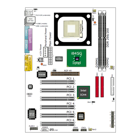
1-1 KT400 Mainboard Layo t
Optional 6-channel A dio-o t Connector

10
KT400
1-2 Mainboard Specifications
1-2.1 CPU Socket
CPU Socket 462 (Socket A) on board, supporting AMD Athlon, Athlon
XP and Duron processors and implementing 333/266/200MHz system
bus
1-2.2 System Chipsets
• North Bridge VIA KT400 for managing and supporting 333/266/
200MHz system Bus, AGP 8X/4X interface and DDR 333/266MHz
Memory Interface *with an enhanced support of DDR 400MHz
Memory Module which should have passed Soltek DDR 400 Memory
Module Validation.
• South Bridge VIA VT8235 working with North Bridge KT400 supporting
the V-Link, LPC Super I/O, PCI interface, ATA133 interface, LAN
interface, USB V2.0 interface, as well as AC’97 Audio 6-channel
interface.
1-2.3 Memory
3 DDR DIMM 184-pin slots on board :
• Supporting unregistered, non-ECC *DDR 400/333/266/200 SDRAM
up to 3 GBs (DDR 400 Module supported conditionally)
• Supporting installation of mixed volumes yet same type of DDR
SDRAM modules
*Soltek Computer Inc. typically runs a DDR 400 Memory Module
Validation Program for Chipset VIA KT400/P4X400A. Detailed
information is available in Soltek Web Site: www.soltek.com.tw
1-2.4 BIOS
• Supporting Plug & Play V1.0
• Flash Memory for easy upgrade
• Supporting BIOS Writing Protection and Year 2000 compliant
• Supporting BIOS Setup (See Chapter 4 BIOS Setup)
1-2.5 Accelerated Graphics Port (AGP) Interface
AGP Controller embedded on board, supporting:
• 1.5V(8X/4X) power mode only, 1 AGP Slot supported
• 8X 66MHz AD and SBA signaling; AGP pipelined split-transaction
longburst transfers up to 2GB/sec.
• AGP 8X/4X supported, AGP V3.0 compliant

11
Chapter 1 Specification
1-2.7 M lti-I/O F nctions
• PCI EIDE Controller, supporting:
-- 2 ATA 133 / 100 / 66 IDE connectors supporting up to 4 IDE devices
• Dedicated IR Functions:
-- 1x5 IR connector dedicated to IR function with Infrared-IrDA (HPSIR)
and ASK (Amplitude Shift Keyed) IR
• Multi-mode parallel data transfer:
-- Standard mode, high speed mode ECP and enhanced mode EPP
• Floppy Drive Connector:
-- 1 FDD connector supporting 2 floppy drives with drive swap support
• Universal Serial Bus Transfer Mode:
-- USB V2.0 compliant, 480 Mb/s USB Bus, supporting Win 98 and later
operating systems; USB drivers provided in Support CD for installation
-- 2 built-in USB connectors and 2 more USB pin-headers which require 2
optional USB cables to provide 4 more USB ports
-- USB Wake-up function supported by USB ports with BIOS Setup and
Jumper setting
• PS/2 Keyboard and PS/2 Mouse
• UARTs (Universal Asynchronous Receiver / Transmitter):
-- 2 complete serial ports (COM1 & COM2) on board
1-2.8 Expansion Slots
• 6 PCI Bus Master slots
• 1 AGP 8X/4X slot
• 3 DDR DIMM slots
1-2.6 Advanced System Power Management
Advanced Configuration and Power Interface incorporated in BIOS for
reducing power consumption :
• ACPI 1.0 compliant (Advanced Configuration and Power Interface)
• APM V1.2 compliant (Legacy Power Management)
• ACPI Suspend function supported
• PS/2 Keyboard & Mouse Power On
• Supporting Ring Signal Power Up Control for Wake-on-LAN (with
Connector WOL1)
• Real Time Clock (RTC) with date alarm, month alarm, and century
field

12
KT400
1-2.9 AC’97 A dio Codec on board
AC’97 Audio Codec 2.2 compliant on board
• Supporting up to 6 channels of PCM audio output
• 6 channel audio consists of Front Left, Front Right, Back Left, Back
Right, Center and Sub-woofer for complete surrround sound effect
• AC’97 Audio Codec Driver enclosed in Support CD for user’s installa-
tion
1-2.10 Hardware Monitor on board
• Hardware Monitor integrated in LPC I/O IT8705F, provides monitor-
ing and alarm for flexible desktop management of hardware voltage,
temperatures and fan speeds.
• Utility Software SmartGuardian for displaying monitoring status is
enclosed in Support CD for user’s installation.
1-2.12 Form Factor
• ATX form factor, ATX power supply V2.03 (20-pin Main Power Con-
nector and 4-pin +12V Power Connector)
• Mainboard size: 305mm x 225mm
1-2.11 Smart Card Reader S pport
• Connector SCR 1” on board to support Smart Card Reader, compli-
ant with Personal Computer Smart Card (PC/SC) working group stan-
dard and smart card (ISO 7816) protocols

13
Chapter 1 Specification
1-3 Mainboard Specification Table
CPU
North Bridge
South Bridge
BIOS
Memory
I/O Chip
AGP interface
Audio
IDE Interface
VGA
PCI Slots
I/O Connectors
Other common
features
Optional
Feature
Socket 462 for AMD Athlon, Athlon XP, Duron CPU
VIA KT400, supporting 333/266/200 MHz FSB
VT8235
AMI BIOS
Supporting DDR *400/333/266 SDRAM, up to 3GB
in 3 DDR SDIMM slots
ITE IT8705F with Hardware Monitor
AGP 8X/4X mode only
AC’97 Audio 2.2 compliant, 6 channel audio
2 ATA 133/100/66 IDE
Not integrated on board
6 PCI Master slots on board
6 USB V2.0, 1 FDD port, 2 COM ports, 1 LPT,
1 IrDA, 1 PS/2 K/B, 1 PS/2 Mouse, 1 SCR slot
BIOS Writing Protection;
Keyboard/ Mouse Power On;
ATX Power Supply V2.03;
ATX form factor
6-channel Audio Out external connectors
KT400 Specifications and Feat res

14
KT400
1-4 Chipset System Block Diagram
Socket 462 + VIA KT400 + VIA VT8235 Diagram
Socket 462
System B s 333/266/200MHz
for AMD CPUs
System
Memory
DDR memory
Interface
DDR 266/
333 SDRAM
AGP Slot AGP 8X/4X
V-Link
PCI B s
AC’97
ATA 133/100/66
4 IDE
Devices
USB B s V2.0
USB
Ports
6 PCI Slots
Audio Codec
(6-channel)
IR
FDD
Serial Ports
Printer Port
Game/MIDI
H/Monitor
BIOS
LPC I/O
IT8705
VIA KT400
North Bridge
VT8235
So th
Bridge
Mouse
Keyboard

16
KT400
Chapter 2 Hardware Setup
1. We recommend to install your CPU before any other components.
For detailed installation instructions of processor, you can also refer
to the pamphlet enclosed in your CPU package.
2. Installing a cooling fan with a good heatsink is a must for proper heat
dissipation for your CPU. Get ready an appropriate fan with heatsink
for proper installation. Improper fan and installation will damage your
CPU.
3. In case CPU Vcore, CPU clock or Frequency Ratio is adjustable on
board, please follow the instructions described in the User Manual
for proper setup. Incorrect setting will cause damage to your CPU.
The following topics are incl ded in this chapter:
To Get Things Ready for Hardware Set p !
2-1 CPU Identification and Installation
2-2 Memory Installation
2-3 AGP Slot Installation
2-4 IDE Connector Installation
2-5 Floppy Drive Connector ( FDC ) Installation
2-6 ATX Power S pply Installation
2-7 J mper Settings
2-8 Other Connectors Config ration
2-9 IRQ Description

17
Chapter 2 Hardware Setup
2-1 CPU Identification and Installation
2-1.1 CPU Identification Legends
Fa ily / Architecture:
A=AMD Athlon Processor
D=AMD Duron Processor
Speed: 0850=850MHz, 0900=900MHz,
1000=1000MHz, 2000=1667MHz,
2200=1800MHz
Package Type: M=Card Module, A=PGA
Voltage: S=1.5V, U=1.6V, P=1.7V, M=1.75V, N=1.8V
Case Te perature: Q=60˚C, X=65˚C, R=70˚C, Y=75˚C,
T=90˚C, S=95˚C
Size of L2 Cache: 1=64Kbyte, 2=128Kbyte, 3=256Kbyte
Max FSB: A=B=200MHz, C=or others=266MHz.
Note: Get the Host CPU Clock by dividing FSB by 2.
(1)
(2)
(3)
(4)
(5)
(6)
(7)
AMD
XXXXXXXXXXX¤
XXXXXXXXXXXX¤
XXXXXXX¤
XXXXXXXXX¤
XXXXXXXXXXX¤
XXXX
AMD XXXX
A 0850 A P T 3 B
1 2 3 4 5 6 7

18
KT400
AMD
SOCKET 462
SOCKET 462
2-1.2 CPU Installation with Socket 462
This series is built with CPU Socket 462 supporting the AMD CPUs
Athlon, Athlon XP and Duron:
• Follow the steps described in this section to install CPU into the on-
board Socket 462.
• After installation of CPU, you must also install a proper cooling fan
on top of the CPU and connect the Fan cable to the CPU fan
connector.
1. First pull sideways the lever of
Socket 462, and then turn it up
900 so as to raise the upper layer
of the socket from the lower
platform.
3. Make sure that all CPU pins have
completely entered the socket
and then lower down the lever
to lock up CPU to socket.
2. Configure Pin 1 of CPU to Pin 1
of the Socket, just as the way
shown in the diagram on the
right. Adjust the position of CPU
until you can feel all CPU pins
get into the pin holes of the
socket.
Pin 1
Pin 1
SOCKET 462
AMD

19
Chapter 2 Hardware Setup
2-2 Memory Installation
184-Pin DIMM Notch Key Definitions
DRAM Key Position Voltage Key Position
Module Latc
• This series supports up to 3GB unbuffered *DDR 400/333/266 SDRAM,
with 3 DDR DIMM slots on board. Do not insert other type of mod-
ules into these slots. Memory support is upgradable to DDR 400 with-
out guarantee of success in BIOS Setup.
*DDR 400 Module is supported on condition that the module has passed
Soltek DDR 400 Memory Module Validation Test. Soltek Computer
Inc. typically runs a DDR 400 Memory Module Validation Program
for Chipset VIA KT400/P4X400A. Detailed information is available in
Soltek Web Site: WWW.soltek.com.tw
• DDR DIMM slot has 184-pins and one notch. Insert a DDR SDRAM
vertically into the 184-pin slot with the notch-to-rib matching.
• Make sure to unplug your power supply before adding or removing
memory module. Failure to do so may cause severe damage to both
your mainboard and the memory module.
• Pay attention to the orientation of the DIMM slots. Forcing a DIMM
into a slot improperly will damage the memory module and slot itself.
2-2.1 To Install DDR SDRAM Mod le
DDR Notch
DDR Rib
2-2.2 To Remove a DIMM
Power off system and press down the holding latches on both sides of
slot to release the module from the DIMM slot.

20
KT400
PCI1
PCI2
PCI3
PCI4
PCI5
VIA
KT400
DIMM1
IDE2
IDE1
Li
Battery
Fan4
1
1
Fan3
Fan5
1
VIA
VT8235
Flash BI S
IT8705
AC'97
Codec
W L1
1
AGP 4X/8X
Clock
Generator
SPK RST PLED Keylock SLED
HDD/LED IR PWR SMI
++
--
+-
1
USB2
1
10
RT2
PCI6
Audio1
14
SCR1
14
1
USB1
1
10
Fan1
FDC
1
DIMM2
LED1
ATX Main Power
1
JBAT1
1
USB1
PS/2 K/B
Mouse
(on top)
(underside)
USB0
(underside)
SOCKET 462
RT1
DIMM3
1
1
CD-In1
DDR 333/266MHz
3
4
LPC I/
LPT1
C M2 C M1
Line
ut
Game/MIDI Port
Line
In
Mic
RTL
ALC650
1
Fan2
7
JCLK1
1
Jp1
1
Jp4
1
Jp3
(DDR 400MHz conditionally supported)
5
9
1
+12V Power
(on top)
DDR DIMM Slots
(184-pin)
2-2.3 Warning Indicator LED1: DIMM Slots Powered On
An indicator LED1 is designed on board. Whenever system is started
or is in STR status (Suspend to RAM), all the DIMM slots on board will
also get powered on with the set voltage, resulting in LED1 lighting up.
This indicator LED1 is to warn users that, whenever DIMM slot is pow-
ered on, no memory module should be removed from or added into it.
LED1
DIMM Slots Powered
On Indicator

21
Chapter 2 Hardware Setup
2-3 AGP Slot Installation
The AGP slot on board supports 1.5V AGP 8X/4X card only. A Rib is
specifically added to the 8X/4X slot so as to match the AGP 8X/4X card.
To insert a 3.3V AGP 2X card into the AGP 4X slot will damage the
system chip and burn the 1.5V circuitry.
An AGP 8X card will support a data transfer rate up to 2GB/sec., while
an AGP 4X card will provide 1GB/sec transfer rate.
PCI1
PCI2
PCI3
PCI4
PCI5
VIA
KT400
DIMM1
IDE2
IDE1
Li
Battery
Fan4
1
1
Fan3
Fan5
1
VIA
VT8235
Flash BI S
IT8705
AC'97
Codec
W L1
1
AGP 4X/8X
Clock
Generator
SPK RST PLED Keylock SLED
HDD/LED IR PWR SMI
++
--
+-
1
USB2
1
10
RT2
PCI6
Audio1
14 SCR1 14
1
USB1
1
10
Fan1
FDC
1
DIMM2
LED1
ATX Main Power
1
JBAT1
1
USB1
PS/2 K/B
Mouse
(on top)
(underside)
USB0
(underside)
SOCKET 462
RT1
DIMM3
1
1
CD-In1
DDR 333/266MHz
3
4
LPC I/
LPT1
C M2 C M1
Line
ut
Game/MIDI Port
Line
In
Mic
RTL
ALC650
1
Fan2
7
JCLK1
1
Jp1
1
Jp4
1
Jp3
(DDR 400MHz conditionally supported)
5
9
1
+12V Power
(on top)
AGP Accelerator
notch
AGP 8X/4X Slot

22
KT400
PCI1
PCI2
PCI3
PCI4
PCI5
VIA
KT400
DIMM1
IDE2
IDE1
Li
Battery
Fan4
1
1
Fan3
Fan5
1
VIA
VT8235
Flash BI S
IT8705
AC'97
Codec
W L1
1
AGP 4X/8X
Clock
Generator
SPK RST PLED Keylock SLED
HDD/LED IR PWR SMI
++
--
+-
1
USB2
1
10
RT2
PCI6
Audio1 14
SCR1
14
1
USB1
1
10
Fan1
FDC
1
DIMM2
LED1
ATX Main Power
1
JBAT1
1
USB1
PS/2 K/B
Mouse
(on top)
(underside)
USB0
(underside)
SOCKET 462
RT1
DIMM3
1
1
CD-In1
DDR 333/266MHz
3
4
LPC I/
LPT1
C M2 C M1
Line
ut
Game/MIDI Port
Line
In
Mic
RTL
ALC650
1
Fan2
7
JCLK1
1
Jp1
1
Jp4
1
Jp3
(DDR 400MHz conditionally supported)
5
9
1
+12V Power
(on top)
2-4 IDE Connector Installation
Gray Connector
Blue Connector
Black Connector
Red Line
IDE Flat Cable (To Mainboard)
(To Slave Device)
(To Master Device)
To install IDE Connector, you may connect the blue connector of IDE
cable to the primary (IDE1) or secondary (IDE2) connector on board,
and then connect the gray connector to your slave device and the black
connector to your master device. If you install two hard disks, you must
configure the second drive to Slave mode by setting its jumpers correctly.
Please refer to your hard disk documentation for the jumper settings.
ATA IDE connectors:
Orient the red line on the IDE
Flat Cable to Pin1.
Pin 1 (to Red Line)
IDE1
IDE2

23
Chapter 2 Hardware Setup
PCI1
PCI2
PCI3
PCI4
PCI5
VIA
KT400
DIMM1
IDE2
IDE1
Li
Battery
Fan4
1
1
Fan3
Fan5
1
VIA
VT8235
Flash BI S
IT8705
AC'97
Codec
W L1
1
AGP 4X/8X
Clock
Generator
SPK RST PLED Keylock SLED
HDD/LED IR PWR SMI
++
--
+-
1
USB2
1
10
RT2
PCI6
Audio1 14
SCR1
14
1
USB1
1
10
Fan1
FDC
1
DIMM2
LED1
ATX Main Power
1
JBAT1
1
USB1
PS/2 K/B
Mouse
(on top)
(underside)
USB0
(underside)
SOCKET 462
RT1
DIMM3
1
1
CD-In1
DDR 333/266MHz
3
4
LPC I/
LPT1
C M2 C M1
Line
ut
Game/MIDI Port
Line
In
Mic
RTL
ALC650
1
Fan2
7
JCLK1
1
Jp1
1
Jp4
1
Jp3
(DDR 400MHz conditionally supported)
5
9
1
+12V Power
(on top)
To install FDC, you should connect the end of FDC cable with single
connector to the board, and connect the other end with two connectors
to the floppy drives.
2-5 Floppy Drive Connector ( FDC ) Installation
To 1st Floppy Drive
To mainboard
To 2nd Floppy Drive
Red line
Floppy Drive Connector:
Orient the red line of the
Floppy Flat Cable to Pin1.
Pin 1 (to Red Line)
FDD Cable

24
KT400
PCI1
PCI2
PCI3
PCI4
PCI5
VIA
KT400
DIMM1
IDE2
IDE1
Li
Battery
Fan4
1
1
Fan3
Fan5
1
VIA
VT8235
Flash BI S
IT8705
AC'97
Codec
W L1
1
AGP 4X/8X
Clock
Generator
SPK RST PLED Keylock SLED
HDD/LED IR PWR SMI
++
--
+-
1
USB2
1
10
RT2
PCI6
Audio1
14
SCR1
14
1
USB1
1
10
Fan1
FDC
1
DIMM2
LED1
ATX Main Power
1
JBAT1
1
USB1
PS/2 K/B
Mouse
(on top)
(underside)
USB0
(underside)
SOCKET 462
RT1
DIMM3
1
1
CD-In1
DDR 333/266MHz
3
4
LPC I/
LPT1
C M2 C M1
Line
ut
Game/MIDI Port
Line
In
Mic
RTL
ALC650
1
Fan2
7
JCLK1
1
Jp1
1
Jp4
1
Jp3
(DDR 400MHz conditionally supported)
5
9
1
+12V Power
(on top)
2-6 ATX Power S pply Installation
To set up Power Supply on this mainboard:
1. Connect the on-board Main Power Connector (20-pin) to the Main
Power Connector (20-pin) of an ATX Power Supplier which should
be of the latest version 2.03 model, and then connect the square-
shaped +12V Power Connector on board to the square-shaped +12V
Power Connector of the Power Supplier.
Warning: Both Main Power Connector and +12 Power Connector
should be connected to power supply; otherwise, system may either
not start or be damaged.
2. This ATX power supplier should be able to provide at least 720mA /
+5V standby power for Wake On LAN and Wake On Modem function.
Main Power Connector
(20-pin)
+12V
5SB
PWR OK
GND
GND
GND
GND
GND
+5V
+5V
-5V
+5V
+5V
+3.3V
+3.3V
-12V
PS ON#
Pin1 Pin11
GND
GND
+3.3V
+12V PowerConnector
1
3
2
4
+12V
GND
GND
+12V
Table of contents
Other SOLTEK Motherboard manuals

SOLTEK
SOLTEK SL-PM800I User manual

SOLTEK
SOLTEK SL-65LIV-T User manual

SOLTEK
SOLTEK SL-85MR2 User manual

SOLTEK
SOLTEK 82440FX User manual

SOLTEK
SOLTEK 85ERV User manual

SOLTEK
SOLTEK SL-54A2-S User manual

SOLTEK
SOLTEK SL-75KV User manual

SOLTEK
SOLTEK SL-KT880E-GR User manual

SOLTEK
SOLTEK SL-B5A-FG User manual

SOLTEK
SOLTEK SL-75DRV5 User manual

SOLTEK
SOLTEK SL-67EV1 Use and care manual

SOLTEK
SOLTEK 85LIR-C User manual

SOLTEK
SOLTEK 65kv User manual

SOLTEK
SOLTEK KT400-C User manual

SOLTEK
SOLTEK KT333A User manual

SOLTEK
SOLTEK SL-85ERV4-R User manual

SOLTEK
SOLTEK SL-B8E-FG User manual

SOLTEK
SOLTEK SL-75LIV User manual

SOLTEK
SOLTEK SL-61A Use and care manual

SOLTEK
SOLTEK SL-63AV User manual