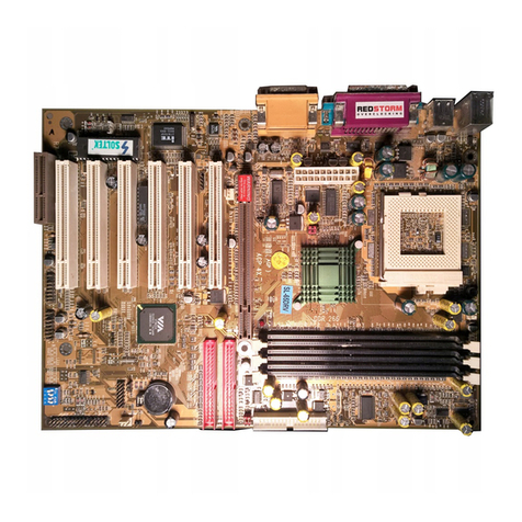
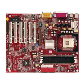
SOLTEK SL-K8T-939FL User manual

4
Contents Contents
Contents
Chapter 1 Specification ............................................. 7
1-1 K8T-939FL Mainboard Layout ..............................................8
1-2 Mainboard Specification Table ..............................................9
1-3 Chipset System Block Diagram........................................... 10
1-4 Mainboard Specifications and Features .............................11
1-4.1 CPU Socket ................................................................................... 11
1-4.2 System Chipsets ........................................................................... 11
1-4.3 Memory ......................................................................................... 11
1-4.4 BIOS............................................................................................... 11
1-4.5 Accelerated Graphics Port (AGP) Interface........................... 12
1-4.6 AC’97 Audio Codec on board .................................................... 12
1-4.7 Advanced System Power Management .................................... 12
1-4.8 IEEE 1394A Interface ................................................................. 12
1-4.9 Multi-I/O Functions .................................................................... 13
1-4.10 SATA / RAID Interface ............................................................. 13
1-4.11 Hardware Monitor on board ................................................... 13
1-4.12 10/100 Ethernet on board......................................................... 13
1-4.13 Form Factor................................................................................ 13
Chapter 2 Hardware Setup ..................................... 14
2-1 CPU Installation with Socket 939 ....................................... 15
2-2 Memory Installation ............................................................. 16
2-2.1 To Install DDR SDRAM Module .............................................. 16
2-2.2 Dual Channel Memory Features............................................... 16
2-2.3 DIMM Powered on ...................................................................... 17
2-3 AGP Slot Installation ............................................................ 17
2-4 IDE Connector Installation ................................................. 18
2-5 SATA / RAID Connectors ..................................................... 19
2-6 Floppy Drive Installation ..................................................... 20
2-7 LED1: Debug LED ................................................................ 21
2-8 ATX Power Supply Installation .......................................... 23
2-9 Jumper Setting ....................................................................... 24
2-9.1 How to tackle the Jumpers: ....................................................... 24
2-9.2 JKB1: Keyboard/Mouse Wake-up ............................................ 25
2-9.3 JBAT1: Clear CMOS .................................................................. 25

5
Contents Contents
2-10 Other Connectors Configuration...................................... 26
2-10.1 On-board FAN Connectors ...................................................... 26
2-10.2 USB Ports and USB Pin-headers ............................................ 27
2-10.3 Chassis Back Panel Connectors .............................................. 28
2-10.4 PS/2 Mouse , PS/2 Keyboard, SPDIF In/Out connector..... 28
2-10.5 RJ45 Connector ......................................................................... 29
2-10.6 CD-ROM Audio Connectors (CD_In).................................... 29
2-10.7 Thermal Detectors ..................................................................... 30
2-10.8 JAUD1: External Audio Connector ....................................... 30
2-10.9 Complex Pin-header (Front Panel Connectors)................... 31
2-10.10 IEEE 1394a Port/Pin-header ................................................. 32
2-10.11 Printer Port: LTP1 .................................................................. 33
Chapter 3 Software Setup ....................................... 34
3-1 To Open Up Support CD:..................................................... 35
3-2 VIA 4-IN-1 Drivers Installation .......................................... 36
3-3 USB 2.0 Driver installation .................................................. 38
3-4 AC’97 Audio Driver Installation......................................... 40
3-4.1 Installing AC’97 8-channel Audio Driver ............................... 40
3-4.2 Verifying 8-channel Audio ........................................................ 41
3-5 LAN Driver Installation ....................................................... 43
3-5.1 Installation ................................................................................... 43
3-5.2 Verification .................................................................................. 43
3-6 Install Hardware Monitor Utility ....................................... 44
3-6.1 Installation ................................................................................... 44
3-6.2 Verification .................................................................................. 45
3-7 RAID Driver Installation ..................................................... 45
Chapter 4 BIOS Setup............................................. 46
4-1 About BIOS Setup ................................................................. 47
4-2 To Run BIOS Setup ............................................................... 47
4-3 About CMOS .......................................................................... 47
4-4 The POST ( Power On Self Test ) ....................................... 47
4-5 To Update BIOS ..................................................................... 48
4-6 BIOS SETUP --- CMOS Setup Utility................................ 51
4-6.1 CMOS Setup Utility .................................................................... 51
4-6.2 Standard CMOS Setup ............................................................... 53
4-6.3 Advanced BIOS Features ........................................................... 55
4-6.4 Advanced Chipset Features ....................................................... 58
4-6.5 Integrated Peripherals................................................................ 60
6
Contents Contents
4-6.5.1. VIA OnChip IDE Device .......................................................... 60

4-6.5.2. VIA OnChip PCI Device: ......................................................... 62
4-6.5.3. Super IO Device:....................................................................... 63
4-6.6 Power Management Setup ......................................................... 64
4-6.7 PnP / PCI Configuration ............................................................ 67
4-6.8 SmartDoc Anti-Burn Shield....................................................... 69
4-6.9 Frequency/Voltage Control ........................................................ 70
4-6.10 Load Optimized Defaults ......................................................... 71
4-6.11 SET SUPERVISOR / USER PASSWORD............................. 71
4-6.12 SAVE & EXIT SETUP .............................................................. 72
4-6.13 EXIT WITHOUT SAVING ...................................................... 72
Chapter 5 VT8237R SATA RAID........................... 73
5-0 About Disk Array................................................................... 74
5-0-1 Disk Array Interpretation.......................................................... 74
5-0-2 Disk Array Member .................................................................... 74
5-0-3 Disk Array Types Supported by VT8237R ............................. 74
5-1 First Step to Set Up SATA RAID System .......................... 75
5-2 Enable SATA-RAID Interface with System BIOS ........... 76
5-3 To Enter VIA Tech. RAID BIOS Setup .............................. 77
5-4 Using VIA RAID BIOS Setup to Create Disk Array ....... 78
5-5 Using VIA RAID BIOS Setup to change Array mode ..... 82
5-6 To Install SATA RAID Driver.............................................. 84
5-6-1 To Install SATA RAID Driver on Windows 2000/XP ............ 84
5-6-2 To Install SATA RAID Driver on Windows 98SE/ME .......... 85

7
SL-K8T-939FL Chapter 1 Specification
Topics included in this chapter are:
1-1 Mainboard Layout
1-2 Specification Table
1-3 Chipset System Block Diagram
1-4 Mainboard Specifications and Features
Introduction
Chapter 1 Specification
** If any difference is found between this manual and the Main-
board you are using, please look up the ERRATA/UPDATE Slip
enclosed inside for the correction or updated information, or
else contact the Mainboard Dealer or visit our Web Site for the
latest manual update.
This mainboard features an integration of the powerful AMD Athlon
64 939 processors and the North Bridge VIA K8T800Pro plus South
Bridge VT8237R, with which the whole system performance supports
HyperTransport Bus up to 1GHz.
VIA K8T800Pro plus VT8237R supports on-board AMD processors
to implement HyperTransport link, running at up to 8GB/s, the AGP 8X/
4X interface, the LPC Super I/O, Dual Channel DDR 400/333/266
SDRAM, the 8-channel AC’97 Audio interface, the USB 2.0 interface,
ATA 133/100/66 data transfer rate, and Serial ATA RAID interface. This
chapter is to introduce to users every advanced function of this high
performance integration.

8
SL-K8T-939FL Chapter 1 Specification
PCI 1
PCI 2
PCI 3
PCI 4
PCI 5
VIA
K8T800
IDE1
IDE2
Li
Battery
VIA
VT8237R
FDD1
AGP 8X/4X
JBAT1
DIMM1
Dual Channel DDR 400/333/266MHz
PS/2 K/eyboard
Mouse
(on top)
Fan1
USB2
1
CD-IN
JAUD1
1
1
ALC850
Fan3
DIMM2
1
1
Line in
(ontop)
LineOut/FrontSpeakerOut
RearSpeakerOut
DIMM3
DIMM4
VIA
VT6103L
1
IEEE1
10
1
VT6307
VIA
USB3
1
1
BIOS
LPC I/O
IT8705F
HDD IR PWR
1
SPK RST
+
-
+
-
PWLED
NJ1
LED
ATA 1
LTP1
1
JKB1
COM1
RJ45
(on top)
(on top)
Out
SPDIF
USB port
IEEE1394
(on top)
PW2
+12V Power
PW1
Main Power
1
RT1
MicIn(underside)
LineIn
(ontop)
Center/SubwooferOut
SideSpeaker
Socket 939
Pro
Fan4
FAN2
SPDIF
LED2
LED1
In
USB port
USB port
USB port
1-1 K8T-939FL Mainboard Layout

9
SL-K8T-939FL Chapter 1 Specification
1-2 Mainboard Specification Table
K8T-939FL Specifications and Features
VIA VT8237R
Supporting Dual Channel DDR 400/333/266
SDRAM, up to 4GB in 4 DDR SDIMM slots
ITE IT8705F with Hardware Monitor
AGP 8X/4X mode only
AC’97 Audio 2.3 compliant, 8 channel audio
2 ATA 133/100/66 IDE Connector
5 PCI Master slots on board
8 USB V2.0, 1 FDD port, 1 COM port, 1 LPT,1
IrDA, 1 PS/2 K/B, 1 PS/2 Mouse, 1 SPDIF-in, 1
SPDIF-out
PS/2 Keyboard/ Mouse Wake up;
Not integrated on board
CPU
North Bridge
South Bridge
Memory
I/O Chip
AGP interface
Audio
IDE Interface
VGA
PCI Slots
I/O Connectors
Other Common
Feature
Serial ATA RAID
Interface
VIA VT6103L 10/100 Ethernet ControllerNetwork
VIA VT6307 IEEE1394 Controller on board
supporting 2 IEEE1394 ports.
IEEE 1394
Interface
2 Serial ATA connectors supported by VT8237R
Debug LED
Socket 939 for AMD Athlon 64 CPUs
VIA K8T800Pro, supporting up to 1GHz Hyper
Transport

10
SL-K8T-939FL Chapter 1 Specification
1-3 Chipset System Block Diagram
Socket 939 + VIA K8T800 Pro + VIA VT8237R Diagram
Socket 939
AMD Athlon 64
System
Memory
Dual Channel
DDR 400/333/
266 SDRAM
AGP Slot AGP 8X/4X
PCI Bus
AC’97 2.3
ATA 133/100/66
4 IDE
Devices
USB Bus V2.0
8 USB
Ports
5 PCI Slots
Audio Codec
(8-channel)
IR
FDD
Serial Port
Printer Port
H/Monitor
BIOS
LPC I/O
IT8705F
North Bridge
VT8237R
VIA K8T800
South Bridge
8x V-Link
533MB/Sec
RJ45
VT6103L
Keyboard & Mouse
2 SATA ports Serial ATA/RAID
10/100
Ethernet
2 IEEE1394 ports
VIA
VT6307
HyperTransport Link
Pro

11
SL-K8T-939FL Chapter 1 Specification
1-4 Mainboard Specifications and Features
1-4.1 CPU Socket
CPU Socket 939 on board, supporting AMD Athlon 64 processors, imple-
menting up to 1GHz Hyper Transport Speed (System Bus) designed to
be capable of operating up to 2000MT/s with a resulting bandwidth of
up to 8 Gbytes/s and integrated Memory Controller which supports up
to DDR SDRAM at 200MHz
1-4.2 System Chipsets
North Bridge K8T800Pro:
• 8-bit / 200 MHz operation with speed up to 16-bit, 1GHz operation (8
GB/s total bandwidth)
˚ AGP V3.0 compliant with 8x transfer mode
South Bridge VIA VT8237R
• Working with North Bridge, VIA VT8237R supporting the 8X V-Link,
LPC Super I/O, PCI interface, ATA133 interface, USB V2.0 interface,
Audio interface as well as Serial ATA RAID interface
1-4.3 Memory
4 DDR DIMM 184-pin slots on board for non-ECC Dual Channel DDR
400/333/266 SDRAMs:
• DIMMs to be populated in identical pairs for Dual Channel operation
• Installation of mixed volumes yet same type of DDR SDRAM mod-
ules supported .
1-4.4 BIOS
Flash Memory for easy upgrade, and supporting various hardware con-
figuration during booting system (See Chapter 4 BIOS Setup):
• Standard CMOS Features (Times, Date, Hard Disk Type etc.)
• Advanced BIOS Features (Virus Protection, Boot Sequence etc.
• Advanced Chipset Features (AT Clock, DRAM Timing etc.)
• Power Management Features (Sleep timer, Suspend Timer etc.)
• PNP/PCI Configurations (IRQ Settings, Latency Timers etc.)
• Integrated Peripherals (Onboard IO,IRQ, DMA Assign. etc.)
• SmartDoc Anti-Burn Shield (CPU/System Temp.,Fan speed etc.)
• Frequency/Voltage (CPU clock, Voltage of CPU, DIMM, AGP etc.)

12
SL-K8T-939FL Chapter 1 Specification
1-4.5 Accelerated Graphics Port (AGP) Interface
AGP Controller embedded on board, supporting:
• 1.5V(8X/4X) power mode only, 1 AGP Slot supported
• 8X 66MHz AD and SBA signaling; AGP pipelined split-transaction
longburst transfers up to 2GB/sec.
• AGP 8X/4X supported, AGP V3.0 compliant
1-4.6 AC’97 Audio Codec on board
AC’97 Audio Codec Realtek ALC850 on board
• Supporting 8-channel display of PCM audio output
• 8 channel audio consists of Front-Out, Surround-Out, Center-Out,
Surround-Back-Out, MIC-In, Line-In, and Front-MIC-In for complete
surround sound effect
• SPDIF In/Out connector integrated in Back Panel supported by
ALC850 for digital interface format input/out.
• AC’97 Audio Codec Driver enclosed in Support CD for user’s
installation.
1-4.7 Advanced System Power Management
Advanced Configuration and Power Interface incorporated in BIOS for
reducing power consumption :
• ACPI 1.0 compliant (Advanced Configuration and Power Interface)
• APM V1.2 compliant (Legacy Power Management)
• ACPI Suspend function supported
• PS/2 Keyboard & Mouse Wake-up
• Real Time Clock (RTC) with date alarm, month alarm, and century
field
1-4.8 IEEE 1394A Interface
The IEEE 1394A Controller, VIA VT6307 chipset on board, providing
enhanced PC connectivity for a wide range of devices, including con-
sumer audio/video components, storage periperals, and other portable
devices.
• PCI-bus based open host controller, compliant with IEEE 1394A-2000
standard for high performance serial bus
• Supporting two fully compliant ports with Plug and Play-compatible
expansion interface. The IEEE 1394A controller provides up to 400MB/
sec transfer rate to fulfill various requirments of any multimedia
devices.

13
SL-K8T-939FL Chapter 1 Specification
1-4.11 Hardware Monitor on board
• Hardware Monitor integrated in LPC I/O IT8705F, providing monitor-
ing functions on hardware voltage, temperatures and fan speeds.
• Utility Software Soltek Hardware Monitor for displaying monitor sta-
tus is enclosed in Support CD for user’s installation.
1-4.13 Form Factor
• ATX Form Factor, ATX Power Supply
• Mainboard size: 305mm x 245mm
1-4.12 10/100 Ethernet on board
PCI local bus 10/100 Ethernet Controller VT6103L on board:
• Supporting 10/100Mb data transfer
• Supporting Wake On LAN function through the on-board RJ45 LAN
Connector
1-4.10 SATA / RAID Interface
Serial ATA / RAID Interface supported by VT8237R:
• Supporting 2 Serial ATA / RAID connectors for 2 SATA Hard Disks
with 150Mb/s transfer rate
• Serial ATA RAID Drivers enclosed in Support CD/Floppy Diskette for
user’s installation
• Supporting RAID 0, 1 configuration
• PS/2 Keyboard and PS/2 Mouse
• UARTs (Universal Asynchronous Receiver / Transmitter):
-- 1 complete serial port (COM1) on board.
1-4.9 Multi-I/O Functions
• PCI EIDE Controller, supporting:
-- 2 ATA 133 / 100 / 66 IDE connectors supporting up to 4 IDE devices
• Dedicated IR Functions:
-- 1x5 IR connector dedicated to IR function with Infrared-IrDA (HPSIR)
and ASK (Amplitude Shift Keyed) IR
• Multi-mode parallel data transfer:
-- Standard mode, high speed mode ECP and enhanced mode EPP
• Floppy Drive Connector:
-- 1 FDD connector supporting 2 floppy drives with drive swap support
• Universal Serial Bus Transfer Mode:
-- USB V2.0 compliant, 480 Mb/s USB Bus, supporting Windows 98 and
later operating systems; USB drivers provided in Support CD for installation
-- 4 built-in USB connectors and 2 more USB pin-headers which require 2
optional USB cables to provide 4 more USB ports

14
SL-K8T-939FL Chapter 2 Hardware Setup
Chapter 2 Hardware Setup
1. We recommend to install your CPU before any other components.
For detailed installation instructions of processor, you can also refer
to the pamphlet enclosed in your CPU package.
2. Installing a cooling fan with a good heatsink is a must for proper heat
dissipation for your CPU. Get ready an appropriate fan with heatsink
for proper installation. Improper fan and installation will damage your
CPU.
3. In case CPU Vcore, CPU clock or Frequency Ratio is adjustable on
board, please follow the instructions described in the User Manual
for proper setup. Incorrect setting will cause damage to your CPU.
The following topics are included in this chapter:
To Get Things Ready for Hardware Setup !
2-1 CPU Installation with Socket 939 ....................................... 15
2-2 Memory Installation ............................................................. 16
2-2.1 To Install DDR SDRAM Module .............................................. 16
2-2.2 Dual Channel Memory Features............................................... 16
2-2.3 DIMM Powered on ...................................................................... 17
2-3 AGP Slot Installation ............................................................ 17
2-4 IDE Connector Installation ................................................. 18
2-5 SATA / RAID Connectors..................................................... 19
2-6 Floppy Drive Installation ..................................................... 20
2-7 LED1: Debug LED ................................................................ 21
2-8 ATX Power Supply Installation .......................................... 23
2-9 Jumper Setting ....................................................................... 24
2-9.1 How to tackle the Jumpers: ....................................................... 24
2-9.2 JKB1: Keyboard/Mouse Wake-up............................................ 25
2-9.3 JBAT1: Clear CMOS .................................................................. 25
2-10 Other Connectors Configuration...................................... 26

15
SL-K8T-939FL Chapter 2 Hardware Setup
2-1 CPU Installation with Socket 939
This series is built with CPU Socket 939 supporting the AMD CPUs
Athlon 64:
1. Socket 939 supported by a
cooling Fan Base.
2. Pull up the lever to
release socket lock.
Socket 939
Socket 939 Lever
Pin 1 position
3. Insert CPU into Socket 939,
CPU Pin1 to Socket Pin1.
Pull up Lever
CPU Pin 1 to Socket Pin 1. Pull down Lever to fix CPU.
5. Install cooling fan into Fan Base.
4. Pull down Lever to fix CPU
to Socket 939
Cooling Fan Latch
Cooling Fan
Latch Connect Fan Power
connector to Mainboard
CPU Fan Power connector.
(Attention: This CPU Fan
connector is only an
example for illustration.)

16
SL-K8T-939FL Chapter 2 Hardware Setup
DRAM Key Position Voltage Key Position
2-2 Memory Installation
• Make sure to unplug your Power Supply before adding or removing
memory module. Failure to do so may cause severe damage to both
your mainboard and the memory module.
• Pay attention to the orientation of the DIMM slots. Forcing a DIMM in
a socket improperly will damage the memory module and slot.
• Make sure you have the right type of memory module for your
mainboard.
• Dual Channel Memory Configuration is formed by couple of identical
DDR SDRAMs.
• Matched DIMMs need to have identical density, DRAM technology,
DRAM bus width, and equal number of memory banks.
• This series supports up to 4GB unbuffered Dual Channel DDR 400/
333/266 SDRAM, with 4 DDR DIMM slots on board. Do not insert
other type of modules into these slots.
• The dual memory controller can double the DDR memory bandwidth
up to 6.4GB/s with DDR400, 5.4GB/s with DDR333 and 4.2GB/s with
DDR266.
2-2.2 Dual Channel Memory Features
2-2.1 To Install DDR SDRAM Module
Populate Bank A / Bank B / Bank A+Bank B with identical DIMMs
Slot Rib
(2.5V Voltage Key) DDR Notch
184-Pin DIMM Notch Key Definition
Module Latch
DIMM1
DIMM2
DIMM3
DIMM4 Bank B
Bank A
To Boot PC with Dual Channel Memory Configuration
Populate DIMM1 / DIMM3 / DIMM1 + DIMM3 with identical DIMMs
To Boot PC with Single Channel Memory Configuration
(Note: DIMM2 / DIMM4 / DIMM2 + DIMM4 cannot boot PC.)

17
SL-K8T-939FL Chapter 2 Hardware Setup
PCI 1
PCI 2
PCI 3
PCI 4
PCI 5
VIA
K8T800
IDE1
IDE2
Li
Battery
VIA
VT8237R
FDD1
AGP 8X/4X
JBAT1
DIMM1
Dual Channel DDR 400/333/266MHz
PS/2 K/eyboard
Mouse
(on top)
Fan1
USB2
1
CD-IN
JAUD1
1
1
ALC850
Fan3
DIMM2
1
1
Linein
(ontop)
LineOut/FrontSpeakerOut
RearSpeakerOut
DIMM3
DIMM4
VIA
VT6103L
1
IEEE1
10
1
VT6307
VIA
USB3
1
1
BIOS
LPC I/O
IT8705F
HDD IR PWR
1
SPK RST
+
-
+
-
PWLED
NJ1
LED
ATA1
LTP1
1
JKB1
COM1
RJ45
(on top)
(ontop)
Out
SPDIF
USB port
IEEE1394
(on top)
PW2
+12V Power
PW1
Main Power
1
RT1
MicIn(underside)
LineIn
(on top)
Center/SubwooferOut
SideSpeaker
Socket 939
Pro
Fan4
FAN2
SPDIF
LED2
LED1
In
USB port
USB port
USB port
2-3 AGP Slot Installation
The AGP slot on board supports 1.
5V AGP 8X/4X card only. A Rib is
specifically added to the 8X/4X slot
so as to match the AGP 8X/4X card.
To insert a 3.3V AGP 2X card into
the AGP 4X slot will damage the
system chip and burn the 1.5V
circuitry.
An AGP 8X card will support a data
transfer rate up to 2GB/sec., while
an AGP 4X card will provide 1GB/
sec transfer rate.
AGP Accelerator
notch
AGP 8X/4X Slot
• LED2 is designed on board to light
up as soon as DIMM slots are pow-
ered on
• When ever LED2 lights up, it indicats
that DIMMs are powered on and no
memory module should be removed
from or inserted into the DIMM slot.
• To remove or insert a memory
module, LED2 should not be on.
2-2.3 DIMM Powered on
LED2 on to indicate that DIMM
slots onboard are powered on.

18
SL-K8T-939FL Chapter 2 Hardware Setup
PCI 1
PCI 2
PCI 3
PCI 4
PCI 5
VIA
K8T800
IDE1
IDE2
Li
Battery
VIA
VT8237R
FDD1
AGP 8X/4X
JBAT1
DIMM1
Dual Channel DDR 400/333/266MHz
PS/2 K/eyboard
Mouse
(on top)
Fan1
USB2
1
CD-IN
JAUD1
1
1
ALC850
Fan3
DIMM2
1
1
Linein
(on top)
LineOut/FrontSpeakerOut
RearSpeakerOut
DIMM3
DIMM4
VIA
VT6103L
1
IEEE1
10
1
VT6307
VIA
USB3
1
1
BIOS
LPC I/O
IT8705F
HDD IR PWR
1
SPK RST
+
-
+
-
PWLED
NJ1
LED
ATA 1
LTP1
1
JKB1
COM1
RJ45
(on top)
(ontop)
Out
SPDIF
USB port
IEEE1394
(on top)
PW2
+12V Power
PW1
Main Power
1
RT1
MicIn(underside)
LineIn
(ontop)
Center/SubwooferOut
SideSpeaker
Socket 939
Pro
Fan4
FAN2
SPDIF
LED2
LED1
In
USB port
USB port
USB port
2-4 IDE Connector Installation
To install IDE Connector, you may connect the blue connector of IDE
cable to the primary (IDE1) or secondary (IDE2) connector on board,
and then connect the gray connector to your slave device and the black
connector to your master device. If you install two hard disks, you must
configure the second drive to slave mode by setting its jumpers correctly.
Please refer to your hard disk documentation for the jumper settings.
ATA IDE connectors:
Orient the red line on the IDE
Flat Cable to Pin1.
Pin 1 (to Red Line of
IDE cable)
IDE2
IDE1
Gray connector
Blue connector
Black connector
Red line
(To Mainboard)
(To Slave device)
(To Master Device)
IDE Flat Cable
80-conductor
cable

19
SL-K8T-939FL Chapter 2 Hardware Setup
PCI 1
PCI 2
PCI 3
PCI 4
PCI 5
VIA
K8T800
IDE1
IDE2
Li
Battery
VIA
VT8237R
FDD1
AGP 8X/4X
JBAT1
DIMM1
Dual Channel DDR 400/333/266MHz
PS/2 K/eyboard
Mouse
(on top)
Fan1
USB2
1
CD-IN
JAUD1
1
1
ALC850
Fan3
DIMM2
1
1
Linein
(on top)
LineOut/FrontSpeakerOut
RearSpeakerOut
DIMM3
DIMM4
VIA
VT6103L
1
IEEE1
10
1
VT6307
VIA
USB3
1
1
BIOS
LPC I/O
IT8705F
HDD IR PWR
1
SPK RST
+
-
+
-
PWLED
NJ1
LED
ATA 1
LTP1
1
JKB1
COM1
RJ45
(on top)
(ontop)
Out
SPDIF
USB port
IEEE1394
(on top)
PW2
+12V Power
PW1
Main Power
1
RT1
MicIn(underside)
LineIn
(ontop)
Center/SubwooferOut
SideSpeaker
Socket 939
Pro
Fan4
FAN2
SPDIF
LED2
LED1
In
USB port
USB port
USB port
Serial ATA Hard Disk
2-5 SATA / RAID Connectors
Serial ATA Cable
Serial ATA Power Cable
To Power Supply
SATA Power Connectors
ATA1
(2 ports)
(optional)
Serial ATA Connectors
SATA Connectors supported
by VT8237R for 2 SATA/RAID
Hard Disks setup.
2 Serial ATA connectors for 2 SATA Hard Disks with RAID mode are
supported by the South Bridge VIA VT8237R. Please see Chapter 5
Disk Array Installation for detail RAID installaion.

20
SL-K8T-939FL Chapter 2 Hardware Setup
PCI 1
PCI 2
PCI 3
PCI 4
PCI 5
VIA
K8T800
IDE1
IDE2
Li
Battery
VIA
VT8237R
FDD1
AGP 8X/4X
JBAT1
DIMM1
Dual Channel DDR 400/333/266MHz
PS/2 K/eyboard
Mouse
(on top)
Fan1
USB2
1
CD-IN
JAUD1
1
1
ALC850
Fan3
DIMM2
1
1
Linein
(ontop)
LineOut/FrontSpeakerOut
RearSpeakerOut
DIMM3
DIMM4
VIA
VT6103L
1
IEEE1
10
1
VT6307
VIA
USB3
1
1
BIOS
LPC I/O
IT8705F
HDD IR PWR
1
SPK RST
+
-
+
-
PWLED
NJ1
LED
ATA 1
LTP1
1
JKB1
COM1
RJ45
(on top)
(ontop)
Out
SPDIF
USB port
IEEE1394
(on top)
PW2
+12V Power
PW1
Main Power
1
RT1
MicIn(underside)
LineIn
(ontop)
Center/SubwooferOut
SideSpeaker
Socket 939
Pro
Fan4
FAN2
SPDIF
LED2
LED1
In
USB port
USB port
USB port
To install Floppy Drive, you should connect the end of Floppy Drive
cable with single connector to the board, and connect the other end
with two connectors to the floppy drives.
2-6 Floppy Drive Installation
Floppy Drive Connector:
Pin 1 (to Red Line)
FDD Cable
To 1st Floppy Drive To Mainboard
To 2nd Floppy Drive
Red line
Signal Swap End
Orient the red line of the
Floppy Flat Cable to Pin1.

21
SL-K8T-939FL Chapter 2 Hardware Setup
PCI 1
PCI 2
PCI 3
PCI 4
PCI 5
VIA
K8T800
IDE1
IDE2
Li
Battery
VIA
VT8237R
FDD1
AGP 8X/4X
JBAT1
DIMM1
Dual Channel DDR 400/333/266MHz
PS/2 K/eyboard
Mouse
(on top)
Fan1
USB2
1
CD-IN
JAUD1
1
1
ALC850
Fan3
DIMM2
1
1
Linein
(on top)
LineOut/FrontSpeakerOut
RearSpeakerOut
DIMM3
DIMM4
VIA
VT6103L
1
IEEE1
10
1
VT6307
VIA
USB3
1
1
BIOS
LPC I/O
IT8705F
HDD IR PWR
1
SPK RST
+
-
+
-
PWLED
NJ1
LED
ATA 1
LTP1
1
JKB1
COM1
RJ45
(on top)
(ontop)
Out
SPDIF
USB port
IEEE1394
(on top)
PW2
+12V Power
PW1
Main Power
1
RT1
MicIn(underside)
LineIn
(ontop)
Center/SubwooferOut
SideSpeaker
Socket 939
Pro
Fan4
FAN2
SPDIF
LED2
LED1
In
USB port
USB port
USB port
2-7 LED1: Debug LED
A Debug LED is built in on board to display various digital messages
which stand for the running status of the mainboard.
Debug LED
(To run with POST code)

22
SL-K8T-939FL Chapter 2 Hardware Setup
Code Post Routine Description
Early initialize the Super I/O
Initialize Mouse
Initialize onboard audio controller
Check CMOS circuitry and reset CMOS
Video memory test
Setup PS/2 Mouse and reset KB
Initialize USB controller
Test memory of above 1MB, using Virtual 8086 mode, page mode and clear
memory
Initialize onboard super I/O
03h
Ah
Bh
12h
2Dh
33h
50h
52h
5Dh
Initialize hard drive controller and any drive
73h
Detect and initialize Serial / parallel
75h Detect and install IDE device
77h
Initialize Option ROMs
85h
Boot
FFh
Turn off chipset and CPU test
First block memory detect
C0
C1
Initialize ACPI sub-system
Initialize floppy disk drive controller and any drive
67h
6Dh

23
SL-K8T-939FL Chapter 2 Hardware Setup
PCI 1
PCI 2
PCI 3
PCI 4
PCI 5
VIA
K8T800
IDE1
IDE2
Li
Battery
VIA
VT8237R
FDD1
AGP 8X/4X
JBAT1
DIMM1
Dual Channel DDR 400/333/266MHz
PS/2 K/eyboard
Mouse
(on top)
Fan1
USB2
1
CD-IN
JAUD1
1
1
ALC850
Fan3
DIMM2
1
1
Linein
(on top)
LineOut/FrontSpeakerOut
RearSpeakerOut
DIMM3
DIMM4
VIA
VT6103L
1
IEEE1
10
1
VT6307
VIA
USB3
1
1
BIOS
LPC I/O
IT8705F
HDD IR PWR
1
SPK RST
+
-
+
-
PWLED
NJ1
LED
ATA 1
LTP1
1
JKB1
COM1
RJ45
(on top)
(ontop)
Out
SPDIF
USB port
IEEE1394
(on top)
PW2
+12V Power
PW1
Main Power
1
RT1
MicIn(underside)
LineIn
(ontop)
Center/SubwooferOut
SideSpeaker
Socket 939
Pro
Fan4
FAN2
SPDIF
LED2
LED1
In
USB port
USB port
USB port
2-8 ATX Power Supply Installation
ATX V2.03 Power Supply is strongly recommended for mainboard run-
ning with this mainboard.
To set up Power Supply on this mainboard:
1. Connect the on-board Main Power Connector (20-pin) to the Main
Power Connector (20-pin) of an ATX Power Supply which can be of
the latest version 2.03 model, and then connect the square-shaped
+12V Power Connector on board to the square-shaped +12V Power
Connector of the Power Supply.
Warning: Both the Main Power Connector and the +12V Power
Connector should be connected to Power Supply; otherwise, the
system may either not start or be damaged.
2. This ATX Power Supply should be able to provide at least 720mA/
+5V standby power for Wake On Lan function.
Main Power
Connector
+12V
5SB
PWR OK
GND
GND
GND
GND
GND
GND
+5V
+5V
-5V
+5V
+5V
+3.3V
+3.3V +3.3V
PS ON#
Pin1 Pin11
-12V
GND
+12V Power Connector
GND
+12V
3
GND
+12V
2
4
1
Table of contents
Other SOLTEK Motherboard manuals

SOLTEK
SOLTEK 75FRN Series User manual

SOLTEK
SOLTEK SL-55F5 User manual

SOLTEK
SOLTEK SL-65D User manual

SOLTEK
SOLTEK SL-85LIR User manual

SOLTEK
SOLTEK SL-65ME-T User manual

SOLTEK
SOLTEK SL-85LIR3 User manual

SOLTEK
SOLTEK SL-865G3 User manual

SOLTEK
SOLTEK SL-65EP User manual

SOLTEK
SOLTEK SL-52D2 User manual

SOLTEK
SOLTEK 85DRV5 User manual

SOLTEK
SOLTEK SL-65KIV User manual

SOLTEK
SOLTEK SL-65MIE User manual

SOLTEK
SOLTEK SL-85DR-C User manual

SOLTEK
SOLTEK SL-XP865G-3IG User manual

SOLTEK
SOLTEK SL-65LIV-T User manual

SOLTEK
SOLTEK SL-67EB Plus User manual

SOLTEK
SOLTEK 85MR3 User manual

SOLTEK
SOLTEK SL-75DRV3/75DRV3+ User manual

SOLTEK
SOLTEK 85DIR User manual

SOLTEK
SOLTEK SL-85DRV3 User manual