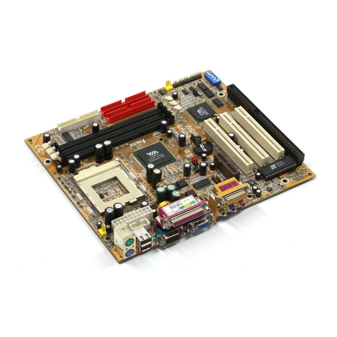
SOLTEK SL-75MIV User manual

SL-75MIV
USER MANUAL V1.1
R

USER NOTICE
Product Model : SL-75MIV
Manual Revision : V1.1
Release Date : March 2001
his Users Guide & Technical Reference is for assisting system
manufacturers and end-users in setting up and installing the
mainboard.
Every effort has been made to ensure that the information in this
manual is accurate. Soltek omputer Inc. is not responsible for print-
ing or clerical errors. Information in this document is subject to
change without notice and does not represent a commitment on the
part of Soltek omputer Inc.
No part of this manual may be reproduced, transmitted, translated
into any language in any form or by any means, electronic or
mechanical, including photocopying and recording, for any purpose
without the express written permission of Soltek omputer Inc.
ompanies and products mentioned in this manual are for identifi-
cation purpose only. Product names appearing in this manual may
or may not be registered trademarks or copyrights of their respec-
tive companies.
Soltek computer inc. Provides this manual “As is “ without war-
ranty of any kind, either express or implied, including but not limited
to the implied warranties or conditions of merchantability or fitness
for a particular purpose. In no event shall Soltek computer inc. Be
liable for any loss or profits, loss of business, loss of use or data,
interruption of business, or for indirect, special, incidental, or con-
sequential damages of any kind, even if Soltek computer inc. Has
been advised of the possibility of such damages arising from any
defect or error in this manual or product.
Copyright © 2001 Solt k Comput r Inc. All Rights R s rv d.
• AMD Athlon ThunderbirdTM, and DuronTM processors are trademarks of AMD orporation.
• VIA, KT-133, VT8363 and VT82 686A are trademarks of VIA orporation.
• Norton AntiVirus, Norton Ghost are trademarks of Symantec orporation.
T
SOLTEK AROUND THE WORLD
SOLTEK COMPUTER INC.
Address : 7F, No. 306-3, Ta-Tung Rd, Sec.1, Hsi- hin, Taipei-
Hsien, Taiwan, R.O. .
Telephone : 886-2-2642-9060
Fax : 886-2-2642-9065
E-mail : [email protected]
Web site : http://www.soltek.com.tw
SOLTEK KOREA INC.
Address : 1002, hungjin Bldg. 53-5 Wonhyo-Ro, 3-Ka,
Yongsan-Ku Seoul 140-113, Korea
Telephone : 82-2-32717400
Fax : 82-2-32717405
E-mail : [email protected]
SOUL TECHNOLOGY EUROPE B.V.
Address : Sydneystraat 52-54 3047 BP Rotterdam, the Nether-
lands
Telephone : 31-10-2457492
Fax : 31-10-2457493
E-mail : [email protected]
Web site : http://www.soultech-europe.com

75MIV
MEMO

5
75MIV
C O N T E N T
Chapt r 1
INTRODUCTION .......................................................... 8
1-1 ITEM LIST HE KUP .................................................................. 8
1-2 PRO ESSOR ............................................................................... 8
1-3 HIPSET ...................................................................................... 8
1-4 ADVAN ED HIGH PERFORMAN E DRAM ONTROLLER ...... 8
1-5 INTEGRATED SAVAGE4 2D/3D VIDEO A ELERATOR ........... 9
1-6 FULL FEATURED A ELERATED GRAPHI S PORTS (AGP)
ONTROLLER.............................................................................. 9
1-7 MULTI-I/O FUN TION .................................................................. 9
1-8 EXTENSION SLOTS .................................................................... 9
1-9 BIOS ........................................................................................... 10
1-10 SOUND ONTROLLER ........................................................... 10
1-11 POWER MANAGEMENT .......................................................... 10
1-12 FROM FA TOR ........................................................................ 10
1-13 HARDWARE MONITORING ..................................................... 10
1-14 OTHERS ................................................................................... 10
1-15 MOTHERBOARD LAYOUT --- 75MIV ....................................... 11
1-16 HIPSET DIAGRAM--- 75MIV.................................................. 12
Chapt r 2
HARDWARE SETUP .................................................. 15
2-1 PU INSTALLATION .................................................................. 15
2-2 MEMORY INSTALLATION .......................................................... 17
2-3 HDD/FDD INSTALLATION .......................................................... 18
2-4 AMD SO KET 462 PRO ESSOR MARKING IDENTIFI ATION ..... 19
2-5 PU EXTERNAL FREQUEN Y SETTING (SW1) ..................... 20
2-6 PRO ESSOR ORE VOLTAGE SELE T (SW2 DIP1-DIP6) .... 21
2-7 FREQUEN Y RATIO SELE T (SW3 DIP1-DIP5) ..................... 22

6
75MIV
2-8 JUMPER DEFINITIONS ............................................................. 23
2-8.1 ONBOARD FAN ONNE TOR (FAN1/FAN2/FAN3) .............. 23
2-8.2 USB PORT SELE T-1 (JP13/JP15) ....................................... 24
2-8.3 USB PORT SELE T-2 (JP12/JP14) ....................................... 24
2-8.4 USB WAKE UP (JUSB1) ......................................................... 25
2-8.5 ONBOARD A 97 ODE SELE T (J OD1) ......................... 25
2-8.6 WAKE ON LAN FUN TION (WOL1) ....................................... 26
2-8.7 LEAR MOS DATA (JBAT1) ................................................ 27
2-8.8 D-ROM AUDIO ONNE TOR ( D-IN1/ D-IN2) ................. 28
2-8.9 THERMAL SENSOR ONNE TOR (RT2) ............................ 28
2-9 ONNE TORS .......................................................................... 29
2-9.1 ON1 ...................................................................................... 29
2-9.2 HASSIS PANEL ONNE TOR............................................ 32
2-9.3 ATX POWER SUPPLY ONNE TOR .................................... 33
2-9.4 PS/2 MOUSE AND PS/2 KEYBOARD .................................... 33
2-9.5 OMMUNI ATION AND NETWORKING RISER SLOT ( NR)34
2-9.6 SE OND USB ONNE TOR ................................................. 35
2-9.7 IRQ DES RIPTION ................................................................. 36
Chapt r 3
SOFTWARE SETUP................................................... 39
3-1 ABOUT SUPPORT D ............................................................... 39
3-2 VIA HIPSET DRIVER INSTALLATION (4-IN-1 DRIVER) ......... 39
3-3 ONBOARD S3® SAVAGE4TM VGA DRIVER INSTALLATION .. 42
3-3.1 INSTALL KM133 VGA DRIVER FOR WINDOWS 95/98/SE ... 42
3-3.2 INSTALL KM133 VGA DRIVER FOR WINDOWS NT4.0 ........ 42
3-3.3 INSTALL KM133 VGA DRIVER FOR WINDOWS ME ............ 43
3-3.4 INSTALL S3® SAVAGE4TM VGA DRIVER WINDOWS 2000 .. 43
3-4 A ’97 AUDIO ODE INSTALLATION ..................................... 44
3-5 HARDWARE MONITOR INSTALLATION ................................... 45

7
75MIV
Chapt r 4
BIOS S tup ................................................................48
4-1 INTRODU E THE BIOS ............................................................. 48
4-2 WHAT IS BIOS SETUP ............................................................... 48
4-3 HOW TO RUN BIOS SETUP ...................................................... 48
4-4 WHAT IS MOS ......................................................................... 48
4-5 WHAT IS POST .......................................................................... 49
4-6 BIOS UPGRADE......................................................................... 49
4-6.1 BEFORE UPGRADE BIOS ...................................................... 49
4-6.2 UPGRADE PRO ESS............................................................. 49
4-7 MOS SETUP UTILITY .............................................................. 53
4-8 STANDARD MOS SETUP ........................................................ 54
4-9 ADVAN ED BIOS FEATURES ................................................... 57
4-10 ADVAN ED HIPSET FEATURES .......................................... 62
4-11 INTEGRATED PERIPHERALS ................................................. 67
4-12 POWER MANAGEMENT SETUP............................................. 71
4-13 PNP / P I ONFIGURATION ................................................... 77
4-14 SMARTDO ANTI-BURN SHIELD ........................................... 80
4-15 FREQUEN Y/VOLTAGE ONTROL ....................................... 83
4-16 LOAD OPTIMIZED DEFAULTS ................................................ 84
4-17 SET SUPERVISOR / USER PASSWORD ................................ 85
4-18 SAVE & EXIT SETUP ............................................................... 86
4-19 EXIT WITHOUT SAVING .......................................................... 86

8
75MIV
CHAPTER 1
INTRODUCTION
1-1 ITEM LIST CHECKUP
• Motherboard
• Support D
• User’s Manual
• Bundle Bonus Pack D
• Bundle Bonus Pack Manual
• ATA 66/100 IDE able
• Temperature Sensor able
• RS232 able
• FDD able
1-2 PROCESSOR
• Supports AMD Athlon Thunderbird processors up to 1.5GHz
• Supports AMD Athlon Duron processors up to 1.2GHz
• Supports processor VID (voltage ID) and FID (frequency ID) auto detection
• Supports AMD Athlon processor with 200 and 266MHz Front Side bus.
1-3 CHIPSET
• North Bridge VIA VT8365A (KM-133A) system controller High Performance
Athlon PU Interface
• South Bridge VIA VT82 686B
1-4 ADVANCED HIGH PERFORMANCE DRAM
CONTROLLER
• Supports P 133 and P 100 SDRAM and Virtual hannel Memory (V M)
SDRAM up to 3 DIMMs
• 64-bit data width and 3.3V DRAM interface
• Supports up to 1.5 GB memory space
• Different DRAM types may be used in mixed combinations
• P I-2.2 compliant, 32 bit 3.3V P I interface with 5V tolerant inputs

9
75MIV
1-5 INTEGRATED SAVAGE4 2D/3D VIDEO ACCELERATOR
• Optimized Shared Memory Architecture (SMA)
• 2 to 32 MB frame buffer using system memory
• Floating point triangle setup engine
• Single cycle 128-bit 3D architecture
• 8M triangles/second setup engine
• 140M pixels/second trilinear fill rate
• Full AGP 4X, including sideband addressing and execute mode
• 2D/3D resolutions up to 1920x1440
1-6 FULL FEATURED ACCELERATED GRAPHICS PORTS
(AGP) CONTROLLER
• Synchronous and pseudo-synchronous with the host PU bus with optimal
skew control P I AGP Mode 33MHz/66MHz/100MHz DDR 3x synchro-
nous
• Supports 66MHz 1x, 2x and 4x modes for AD and SBA signaling
• AGP v2.0 compliant
1-7 MULTI-I/O FUNCTION
• Two Ultra DMA 33/66/100 master mode P I EIDE ports
• Two UARTs for complete Serial Ports
• One dedicated IR connector:
--Third serial port dedicated to IR function either through the two complete serial
ports or the third delicated port Infrared-IrDA (HPSIR) and ASK( Amplitude Shift
Keyed) IR
• Multi-mode parallel connector:
--Standard mode, E P and EPP support
• Floppy Disk connector:
--Two FDDs with drive swap support
• Universal Serial Bus connector:
--USB v1.1 and Intel Universal H I v1.1 compatible
--Provides 2 build-in USB ports (another 2 internal USB ports for extensible purpose
require an optional USB connect cable)
• PS/2 keyboard connector
• PS/2 Mouse connector
1-8 EXTENSION SLOTS
• Three P I bus Master slots
• One NR slot
• One AGP 4x mode slot

10
75MIV
• Three DIMM slots
1-9 BIOS
• Award BIOS V6.0
• Supports Plug & Play V1.0
• Flash Memory for easy upgrade
• Year 2000 compliant
• Supports BIOS writing protection
• Supports SMARTDO ANTI-BURN SHIELD
• Supports RedStorm Overclocking Tech
1-10 SOUND CONTROLLER
• SoundBlaster Pro Hardware and Direct Sound Ready A 97 Digital Audio
ontroller with odec onboard
1-11 POWER MANAGEMENT
• A PI 1.0 compliant (Advanced onfiguration and Power Interface)
• APM V1.2 compliant (legacy power management)
• Supports A PI POS mode (Power On Suspend)
• Supports Wake On LAN (WOL) & Wake On Modem (WOM)
• Supports real time clock (RT ) with date alarm, month alarm, and century
field
• Supports USB boot-up Function
1-12 FROM FACTOR
• Micro ATX from factor, 4 layers P B
• Motherboard size 21.0cm x 24.3cm
1-13 HARDWARE MONITORING
• Programmable control, status, monitor and alarm for flexible desktop man-
agement (software include)
• Five-positive voltage monitoring
• Two-temperature monitoring
• 2 Fan-speed monitoring
1-14 OTHERS
• lock generator supports 1 MHz linear clock setting
• Supports DRAM Voltage select Function

11
75MIV
1-15 MOTHERBOARD LAYOUT --- 75MIV
• Default Setting: 100MHz PU External clock.
SOCKET A
USB0
USB1
PS/2
MOUSE
PS/2
K/B
LPT1
COM1VGA
GAME/MIDI PORT
LINE
OUT
LINE
IN
MIC
ATX POWER
VIA
VT8365A
DIMM1
DIMM2
DIMM3
IDE1
IDE2 FDD1
SW1
SW3
ON DIP
1 2 3 4 5
SW2
ON DIP
1 2 3 4 5 6
3 1
JUSB1
FAN1
1 3
RT2
AGP 4X
PCI 1
PCI 2
PCI 3
PCI 1
PCI 2
PCI 3
CNR 1
VIA
VT82C
686B
Li
Batt ry
1
11
FAN3
1 3
1 3
JBAT1
CON1
SAPK RST PLED SLED
HDD/LED IR PWR SUSPEND
++
--
+-
16 30
1 15
RT2
JP12
JP14
JP15
JP13
1 3 1 3
16
1
USB2
1 3
JCOD1
AC'97
Cod c
FLASH BIOS
41
41
CD_IN1
CD_IN2
WOL1
FAN2
1 3
1 3
Clock
G n rator
ON DIP
1 2 3 4 5
LED1
COM 2
1
10

12
75MIV
1-16 CHIPSET DIAGRAM--- 75MIV
• The KM-133A / VT8365A and VT82 686B chipset is a high performance,
cost-effective and energy efficient system controller for the implementation
of AGP / P I / ISA desktop personal computer system based on 64-bit
Socket-A (AMD Athlon) processors.
KM133A Syst m Block Diagram Using th VT82C686B South Bridg
KM133A
VT8365A
North Bridg
552 BGA
South Bridg
352 BGA
VT82C
686B
Pow r Plan & P riph ral Control
GPIO and ACPI Ev nts
Hardwar Monitoring Inputs
K yboard / PS2 Mous
S rial Ports 1 and 2
Parall l Port
Floppy Driv Int rfac
MIDI / Gam Ports
RTC Crystal
PCLK
SMBus
Clock
G n rator
PCISTP#
CPUSTP#
MCLK
In
Data
Addr ss
Out
SDRAM
Clock
Buff r
GCLK
CFWDRST
CONNECT
PROCRDY
GCKRUN#
AGP Bus
PCI Bus
SUSCLK,
SUSST1#
PCKRUN#
ATA 33/66/100
USB Ports 0 - 3
CNR
AC97 Link
M mory Bus
CKE
HCLK
PCLK
SYSCLK, SYSCLK#
INTR, NMI, SMI#, STPCLK#,
IGNNE#, FERR#, A20M#,
PWROK, INIT#, RESET#
Athlon
Host CPU
3D Graphics
Controll r
AC97 Audio Cod c
BIOS ROM

13
75MIV
MEMO

1
75MIV
ATTENTION !!!
1. Pl as r f r to your proc ssor installation or oth r
docum ntation attach d with your CPU for d tail d
installing instruction.
2. Installing a h at sink and cooling fan is n c ssary for
prop r h at dissipation from your CPU. Uncorr ct d
installation may r sult in ov rh ating and damag of
your CPU.
3. B for changing th s tting of CPU Vcor from BIOS
program, us r SHOULD mak sur of corr ct sp cifi-
cation both of CPU CLOCK and RATIO. Uncorr ct d
s tting may caus damag to your CPU.

15
75MIV
CHAPTER 2
HARDWARE SETUP
2-1 CPU INSTALLATION
WARNING:
• Make sure that +5V DV and +3.3 DV capabilities of your power supply
are suitable for the processor.
• Any attempt to operate the AMD Athlon or Duron processor without a suit-
able cooling Fan will result in permanent damage to the processor and
potentially other component within the system.
1. Pull the lever sideways away from the socket, and then raise the lever up
to a 90-degree angle.
2. Take note of the red circle as below picture. While inserting the PU into
the socket, you can find out there is a definite pin orientation for PU and
socket.
SOCKET 462
AMD
SOCKET 462

16
75MIV
3. Make sure that the PU position in the socket tightly, and then put the
lever down to complete the PU installation.
AMD
SOCKET 462

17
75MIV
Installing DIMM
• Mak sur you hav th corr ct m mory modul typ for your
moth rboard.
• Ins rt th modul (s) as shown, DIMMs hav 168-pins and two notch s
that will match with th onboard DIMM sock t, m mory modul s ar
install d by ins rting th m straight into th slot until th y “click” into
plac . Th y only fit in on dir ction so do not forc th m into plac .
R moving DIMM
• Pr ss th holding clips on both sid s of sock t out ward to r l as
th DIMM out of th sock t.
168-Pin DIMM Notch K y D finitions(3.3V)
DRAM K y Position Voltag K y Position
Unbuff r d 3.3V
WARNING!!!
• Mak sur that you unplug your pow r supply wh n adding or r mov-
ing m mory modul s or oth r syst m compon nts. Failur to do so
may caus s v r damag to both your mainboard and xpansion
cards.
• B car ful wh n ins rting or r moving DIMM, forcing a DIMM in or out
of a sock t can b damag d th m mory modul or th sock t. Som of
DIMMs contain EDO or FTP DRAM. Th s DIMM typ s ar incompliant
with th moth rboard, th M/B only supports 3.3V tru SDRAM DIMMs.
2-2 MEMORY INSTALLATION

18
75MIV
SOCKET A
ATX POWER
VIA
VT8365A
DIMM1
DIMM2
DIMM3
IDE1
IDE2
FDD1
SW1
FAN1
1 3
RT2
AGP 4X
PCI 1
PCI 2
PCI 3
PCI 1
PCI 2
PCI 3
VIA
VT82C
686B
Li
Batt ry
1
11
FAN3
1 3 1 3
JBAT1
CON1
SAPK RST PLED SLED
HDD/LED IR PWR SUSPEND
++
--
+-
16 30
1 15
RT2
JP12
JP14
JP15
JP13
1 3 1 3
16
1
USB2
1 3
JCOD1
WOL1
FAN2
1 3
1 3
Clock
G n rator
ON DIP
1 2 3 4 5
• To install HDD (Hard Disk Driv ), you may conn ct th cabl ’s blu
conn ctor to th moth rboard’s primary (IDE1) or s condary IDE
conn ctor, and th n conn ct th gray conn ctor to your slav d vic
and th black conn ctor to your mast r d vic .If you install two hard
disks , you must configur th s cond driv to Slav mod by s tting
its jump r accordingly.Pl as r f r to your hard disk docum ntation
for th jump r s ttings.
• To install FDD (Floppy Disk Driv ), you may conn ct th singl nd to
th board , and conn ct two plugs on th oth r nd to th floppy driv s.
Floppy Disk Drive
onnector:
Orient the red markings
on the floppy ribbon
cable to Pin1.
Hard Disk Drive
onnector:
Orient the red markings
on the IDE ribbon cable
to Pin1.
2-3 HDD/FDD INSTALLATION

19
75MIV
2-4 AMD SOCKET 462 PROCESSOR MARKING IDENTIFICATION
• The following figures and tables describe the product marking for the PGA
(Socket A) versions of the AMD Athlon Model 4 processor and AMD Duron
processor...
AMD
XXXXXXXXXXX
XXXXXXXXXXXX
XXXXXXX
XXXXXXXXX
XXXXXXXXXXX
XXXX
AMD XXXX
A 0850 A P T 3 B
Sp d: 0850= 850MHz, 0900= 900MHz,
1000= 1000MHz, 1100= 1100MHz, tc.
Packag Typ : M= Card Modul , A= PGA.
Op rating Voltag : S= 1.5V, U= 1.6V, P= 1.7V, M= 1.75V, N= 1.8V.
Cas T mp ratur : Q= 60
0
C, X= 65
0
C, R= 70
0
C, Y= 75
0
C,
T= 90
0
C.
Siz of L2 Cach : 1= 64Kbyt , 2= 128Kbyt , 3= 256Kbyt .
Max FSB: A= B= 200MHz, C or oth rs= 266MHz. (For corr ct
FSB s tting, pl as r f r to chapt r 2-5)
Family/Archit ctur :
A= AMD Athlon
TM
Mod l 4 Proc ssor Architur .
D= AMD Duron
TM
Proc ssor Archit ctur .
12 34567 1
2
3
4
5
6
7

20
75MIV
2-5 CPU EXTERNAL FREQUENCY SETTING (SW1)
33.3MHz
100MHz
(D fault) 200MHz
SW1 CPU EXTERNAL CLOCK PCI CLOCK FSB CLOCK
ON DIP
1 2 3 4 5
34.3MHz
103MHz 206MHz
ON DIP
1 2 3 4 5
35.0MHz
105MHz 210MHz
ON DIP
1 2 3 4 5
36.7MHz
110MHz 220MHz
ON DIP
1 2 3 4 5
37.3MHz
112MHz 224MHz
ON DIP
1 2 3 4 5
38.3MHz
115MHz 230MHz
ON DIP
1 2 3 4 5
40.0MHz
120MHz 240MHz
ON DIP
1 2 3 4 5
31.0MHz
124MHz 248MHz
ON DIP
1 2 3 4 5
33.3MHz
133.3MHz 266MHz
ON DIP
1 2 3 4 5
35.0MHz
140MHz 280MHz
ON DIP
1 2 3 4 5
37.5MHz
150MHz 300MHz
ON DIP
1 2 3 4 5
IMPORTANT:
• You may figure out the correct processor type by processor’s OPN
(Ordering Part Numbers), select correct PU external frequency is
key to ensure reliable operation.
• Incorrect PU external frequency or overclocking are not guaranteed
to be stable, we strongly recommended to leave “SW1” at default
setting or legal operation.
Table of contents
Other SOLTEK Motherboard manuals

SOLTEK
SOLTEK SL-67FV1 User manual

SOLTEK
SOLTEK SL-85LIR User manual

SOLTEK
SOLTEK SL-56H5 User manual

SOLTEK
SOLTEK SL-XP865G-3IG User manual

SOLTEK
SOLTEK 86SP2 User manual

SOLTEK
SOLTEK SL-865G User manual

SOLTEK
SOLTEK SL-85DRV3 User manual

SOLTEK
SOLTEK SL-855GEI-FDGR User manual

SOLTEK
SOLTEK 86SP3 User manual

SOLTEK
SOLTEK SL-65F+ User manual

SOLTEK
SOLTEK SL-845GVI User manual

SOLTEK
SOLTEK 865Pro-FGR User manual

SOLTEK
SOLTEK SL-K890-754G User manual

SOLTEK
SOLTEK 85DRV5 User manual

SOLTEK
SOLTEK SL-85DRV+ User manual

SOLTEK
SOLTEK NV400-64 User manual

SOLTEK
SOLTEK SL-65D User manual

SOLTEK
SOLTEK SL-85ERV4-R User manual

SOLTEK
SOLTEK SL-B9D-FGR User manual

SOLTEK
SOLTEK SL-75KV User manual