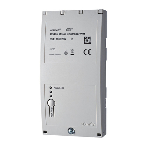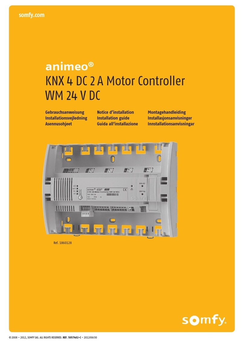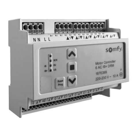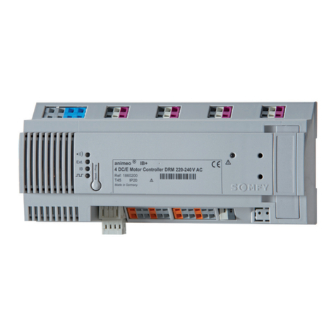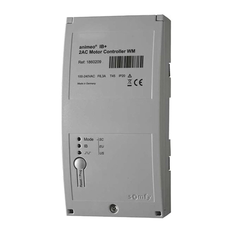
Installation: Ensure each motor controller is mounted and secured as outlined in the instructions included with the
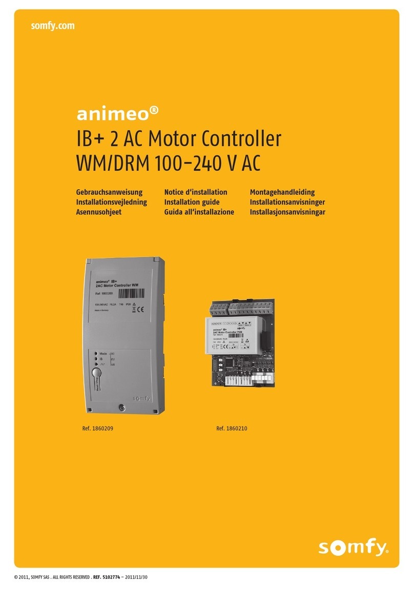
controller. Mounting options are wall mount or din rail mount.
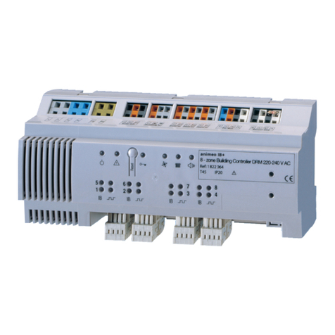
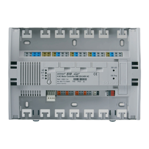
Motor Connections - it is important to follow the same wiring configuration for each motor. For example, if AC motor
controllers are being used the connections should be as follows. Green/earth ground should connect to the green
terminal. The neutral wire should connect to the blue terminal. Directional wires should connect to the grey terminal with
the up and down arrows.
Additionally, wiring DC motors to the motor controller should follow the same method.
Once all motors are connected and input power is applied, it is necessary to test the motor direction. There are two
ways this can be done:
1) Carefully connect the common, up, and down directions of an Animeo switch to the corresponding inputs on the low
voltage terminal block. Verify that pressing the up direction moves the shade UP, while the down button moves the
shade DOWN.
2) Using a wire jumper on the low voltage terminal block input, use a wire jumper to “jump” the common “C” terminal to
the up and down terminals. Verify each direction moves the shade to its appropriate end limit.
*If pressing the up button or initiating a dry contact moves the shade in the down direction, first verify the Animeo
switch is properly connected to the appropriate terminals. If this is correct, reverse the motor’s directional wires
associated with the switch input which is being tested. Note: It is highly recommended to disconnect power prior
to changing any wire configuration.
After the controllers have been properly mounted, wired, and motor directions tested refer to page 13 of the Animeo IB+
Motor Controller instruction booklet (provided) to configure the controller to the desired end product. Note: Failure to set
the correct end product may result in erratic operation. See also MoCo Positioning Key Modes.
Setup : Required components for programming.
1) PC with available serial or usb port
2) RS-232 to RS-485 convertor
3) RS485 ILT3 Programming Software
Prior to programming it is required to install the necessary software along with any drivers that may be required for the
serial device. Once the hardware and software is installed successfully it is imperative the communication parameters are
set to the following. These settings can be accessed in the Device Manager on the pc.
Bits Per Second: 4800
Data Bits: 8
Parity: Odd
Stop Bits: 1
Flow Control: None
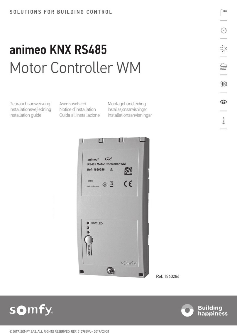
Connect the + and - terminals from the RS-232 to RS-485 converter to the RS-485 terminal block,
located on the far right side on the controller. The + line should connect to one of the A terminals,
while the - line should connect to one of the B terminals. Since both A and B terminals are internally
connected to each other, either terminal connection is allowed.
Programming: Open the RS485 ILT3 Programming Software. On the top left hand side of the program choose the com
port in which your serial device is connected to, then click the Open button to open the selected com port.
Note: the Open button should now say Close.
PE
N
