manuals.online logo
Brands
  1. Home
  2. •
  3. Brands
  4. •
  5. SOMFY
  6. •
  7. Gate Opener
  8. •
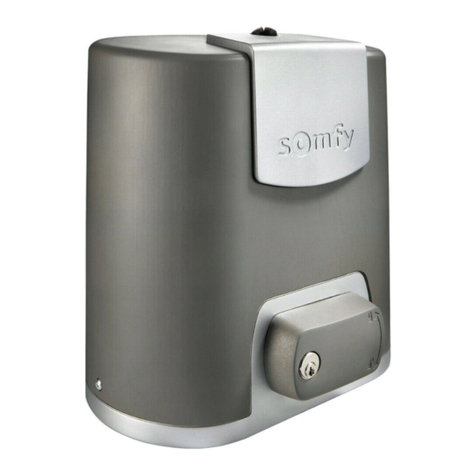
  9. SOMFY Axovia 220A User manual

SOMFY Axovia 220A User manual

Other manuals for Axovia 220A

2

Other SOMFY Gate Opener manuals

SOMFY Elixo 800 User manual

SOMFY

SOMFY Elixo 800 User manual

SOMFY tecnoShades NR0-Rn Installation manual

SOMFY

SOMFY tecnoShades NR0-Rn Installation manual

SOMFY Elixo 500 3S io User manual

SOMFY

SOMFY Elixo 500 3S io User manual

SOMFY Elixo 500 230 V User manual

SOMFY

SOMFY Elixo 500 230 V User manual

SOMFY Elixo 500 3S RTS User manual

SOMFY

SOMFY Elixo 500 3S RTS User manual

SOMFY Ixengo L 24V User manual

SOMFY

SOMFY Ixengo L 24V User manual

SOMFY Elixo 500 230 V User manual

SOMFY

SOMFY Elixo 500 230 V User manual

SOMFY SGA 2000 User manual

SOMFY

SOMFY SGA 2000 User manual

SOMFY Elixo 500 3S RTS User manual

SOMFY

SOMFY Elixo 500 3S RTS User manual

SOMFY Dexxo Pro 800 User manual

SOMFY

SOMFY Dexxo Pro 800 User manual

SOMFY SGS 200 User manual

SOMFY

SOMFY SGS 200 User manual

SOMFY Elixo 500 230 V User manual

SOMFY

SOMFY Elixo 500 230 V User manual

SOMFY Dexxo Smart 800 io User manual

SOMFY

SOMFY Dexxo Smart 800 io User manual

SOMFY EXAVIA 500 User manual

SOMFY

SOMFY EXAVIA 500 User manual

SOMFY AXOVIA 3S User manual

SOMFY

SOMFY AXOVIA 3S User manual

SOMFY 3S io User manual

SOMFY

SOMFY 3S io User manual

SOMFY Elixo 500 230V RTS User manual

SOMFY

SOMFY Elixo 500 230V RTS User manual

SOMFY SGS 201 User manual

SOMFY

SOMFY SGS 201 User manual

SOMFY FX230 User manual

SOMFY

SOMFY FX230 User manual

SOMFY FX24 User manual

SOMFY

SOMFY FX24 User manual

SOMFY SGS 501 User manual

SOMFY

SOMFY SGS 501 User manual

SOMFY SGS 501 User manual

SOMFY

SOMFY SGS 501 User manual

SOMFY Maestria 50 RTS User manual

SOMFY

SOMFY Maestria 50 RTS User manual

SOMFY axovia 400C User manual

SOMFY

SOMFY axovia 400C User manual

Popular Gate Opener manuals by other brands

Nortek Security & Control Mighty Mule HD272 installation manual

Nortek Security & Control

Nortek Security & Control Mighty Mule HD272 installation manual

tousek TURN 10 Installation and operating instructions

tousek

tousek TURN 10 Installation and operating instructions

Nice HySecurity CBOX1050 Installation and programming manual

Nice HySecurity

Nice HySecurity CBOX1050 Installation and programming manual

CAME FROG-PM4 installation manual

CAME

CAME FROG-PM4 installation manual

Aprimatic ONDA 500 installation instructions

Aprimatic

Aprimatic ONDA 500 installation instructions

Turnstiles FSW 900 manual

Turnstiles

Turnstiles FSW 900 manual

Erreka BUL BL33 Quick installation and programming guide

Erreka

Erreka BUL BL33 Quick installation and programming guide

Extel VERA quick guide

Extel

Extel VERA quick guide

Beninca R1-2 WBV quick start guide

Beninca

Beninca R1-2 WBV quick start guide

Erreka VULCAN D user manual

Erreka

Erreka VULCAN D user manual

Motorline professional FORT User& installer's manual

Motorline professional

Motorline professional FORT User& installer's manual

Beninca BOB5024 manual

Beninca

Beninca BOB5024 manual

AGA GATEMASTER 900 HD installation manual

AGA

AGA GATEMASTER 900 HD installation manual

Cardin BL Series manual

Cardin

Cardin BL Series manual

Westfalia 85 27 06 instruction manual

Westfalia

Westfalia 85 27 06 instruction manual

Riello Elettronica CARDIN ACE FAST Instruction handbook

Riello Elettronica

Riello Elettronica CARDIN ACE FAST Instruction handbook

Telcoma ARM Instruction handbook

Telcoma

Telcoma ARM Instruction handbook

Telcoma ACE Instruction handbook

Telcoma

Telcoma ACE Instruction handbook

manuals.online logo
manuals.online logoBrands
  • About & Mission
  • Contact us
  • Privacy Policy
  • Terms and Conditions

Copyright 2025 Manuals.Online. All Rights Reserved.

Notice d’installation Guia de instalacion
Installation guide Montagehandleiding
220 A
Ref: 1 216 012 V5
 Sommaire
1 Consignes de sécurité
2 Composition du Kit
3 Description du boîtier électronique
4 Vérification avant le montage
5 Processus de montage
6 Branchements
7 Processus de réglage
8 Mémorisation des télécommandes
9 Programmation
10 Accessoires SOMFY
11 Caractéristiques techniques
 Contents
1 Safety recommendations
2 Composition of kit
3 Electronic control box description
4 Check before assembly
5 Assembly process
6 Connecting
7 Adjustment process
8 Memorising remote control
9 Programming
10 SOMFY Accessories
11 Technical data
 Inhoudsopgave
1 De veiligheidsinstructies
2 Samenstelling van de kit
3 Beschrijving elektronische besturingskast
4 Controle vóór montage
5 Montageproces
6 Aansluitingen
7 Afstellingsprocedure
8 Zenders toewijzen
9 Instellingen
10 SOMFY accessoires
11 Technische gegevens
 Indice
1 Las consignas de seguridad
2 Composición del kit
3 Descripción de la unidad electrónica
4 Verificación antes del montaje
5 Proceso de montaje
6 Conexiones
7 Proceso de ajuste
8 Memorización del emisor
9 Programación
10 Accesorios SOMFY
11 Caracteristicas
Avant de procéder à l’installation de votre produit, il
est impératif de lire atten-tivement l’ensemble de
cette notice. Suivez précisément chacune des
instructions données et conservez cette notice aussi
longtemps que durera votre produit.
En cas de non respect de ces consignes d’installation,
de graves dommages corporels ou matériels
risqueraient de survenir. SOMFY ne pourrait en être
tenu responsable.
Avant d’installer la motorisation, vérifiez que la
partie entraînée est en bon état mécanique, qu’elle
est correctement équilibrée et qu’elle s’ouvre et se
ferme correctement.
S’assurer que les zones dangereuses (écrasement,
cisaillement, coincement) entre la partie entraînée et
les parties fixes environnantes dû au mouvement
d’ouverture de la partie entraînée sont évitées.
Préserver une zone de dégagement de 500 mm à
l’arrière de chaque vantail lorsque le portail est
complètement ouvert.
Garder à vue votre portail pendant le mouvement.
Tout interrupteur sans verrouillage*** doit être situé
en vue directe de la partie entraînée, mais éloigné
des parties mobiles. Sauf s’il fonctionne avec une clé,
il doit être installé à une hauteur minimale de 1.5m
et ne pas être accessible au public.
Si vous utilisez un interrupteur sans verrouillage***,
assurez-vous que les autres personnes sont tenues à
distance.
*** (exemple : interphone, contact à clé, digicode...)
Before installing your product, all of these
instructions must be carefully read. Follow exactly
each of the instructions given and keep these
instructions as long as your product lasts.
In case these installation instructions are not
respected, serious bodily injury or property damage
mayensue. SOMFY will not be liable for such
damages.
Before installing the motorization, check that the
driven part is in good mechanical condition, that it is
correctly balanced and that it opens and closes
correctly.
Make sure that dangerous areas caused by the
opening movement of the driven part and the
surrounding fixed parts are kept clear (crushing,
shearing, jamming).
Keep an area of 500 mm clear behind each gate leaf
when the gate is completely open.
Keep an eye on your gate while it is moving.
Any non-locking switch*** must be located in a place
directly visible from the driven part but away from the
mobile parts. Unless it functions with a key, it must
be installed at a minimal height of 1.5 m and not be
accessible to the public.
If you use a switch with no locking device***, make
sure that other persons are kept away from it.
*** (example : interphone, locking key, digital code...)
Alvorens over te gaan tot installatie van uw product
dient u deze handleiding in z'n geheel aandachtig
door te lezen. Volg alle instructies zorgvuldig op, en
bewaar de handleiding zolang uw product meegaat.
Bij niet-naleving van de installatievoorschriften zou
er ernstige lichamelijke of materiële schade kunnen
ontstaan. SOMFY kan hiervoor niet aansprakelijk
gesteld worden.
Alvorens de aandrijving te installeren dient u te
controleren of het aangedreven deel in goede
mechanische staat verkeert, dat het goed
uitgebalanceerd is, en op de juiste wijze opent en sluit.
Zorg ervoor dat de gevaarlijke zones (omverwerpen,
afknijpen, klemzetten) tussen het aangedreven deel
en de vaste aangrenzende onderdelen, veroorzaakt
door het openen van het aangedreven deel,
vermeden worden.
Houd rekening met een vrije ruimte van 500 mm aan de
achterkant van elke deur als het toegangshek volledig
open staat.
Houd uw toegangshek in het oog tijdens het open-
en dichtslaan.
Alle schakelaars zonder vergrendeling*** moeten zich
direct in het zicht van het aangedreven deel bevinden,
maar op afstand van de beweegbare delen. Behalve als
deze met een sleutel functioneert, moet deze
geïnstalleerd worden op een minimale hoogte van
1,5m, en niet toegankelijk zijn voor buitenstaanders.
Als u een schakelaar zonder vergrendeling***
gebruikt, zorg er dan voor dat andere personen op
afstand blijven.
*** (bijvoorbeeld: intercom, sleutelcontact, digicode…)
Antes de proceder a la instalación del producto, es
imperativo leer atentamente el conjunto de este
manual. Síganse con precisión todas las
instrucciones proporcionadas y consérvese este
folleto mientras dure el producto.
En caso de no respetarse estas consignas de
instalación, pueden suceder graves daños
corporales o materiales. SOMFY quedaría eximido de
toda responsabilidad.
Antes de instalar la motorización, compruébese que
la parte accionada está en buen estado mecánico,
correctamente equilibrada y que se abre y se cierra
correctamente.
Cerciorarse de que se evitan las zonas peligrosas
(aplastamiento, cizallamiento, atascamiento) entre
la parte accionada y las partes fijas cercanas,
durante el movimiento de abertura de la parte
accionada.
Preservar una zona libre de 500 mm en la parte atrás
de cada hoja cuando el portal esté completamente
abierto.
Mantener la vista sobre el portal durante el
movimiento.
Todo interruptor sin bloqueo*** debe estar situado
en vista directa de la parte accionada, aunque
alejado de las partes móviles. Salvo si funciona con
una llave, debe instalarse a una altura mínima de
1,5 m y no debe ser accesible al público.
Si se utiliza un interruptor sin bloqueo***,
cerciorarse de que las demás personas están a
distancias reglamentarias.
*** (ejemplo: interfono, contacto de llave, código digital...).
 Consignes de sécurité  Safety recommendations  De veiligheidsinstructies  Las consignas de seguridad
1
Vérifiez fréquemment l’installation pour déceler tout mauvais équilibrage
des vantaux ou tout signe d’usure. Ne pas utiliser l’appareil si une
réparation ou un réglage est nécessaire. Vérifier régulièrement l’état du
portail. Les portails en mauvais état doivent être réparés, renforcés, voir
changés avant l’installation. Vérifier régulièrement le bon serrage des vis et
des fixations des différents éléments de l’Axovia.
Frequently check the installation to detect any bad balancing of the gate
leaves or any sign of wear. Do not use the device if repairs or adjustments
are necessary. Check the condition of the gate regularly. Gates in bad
condition must be repaired, reinforced or changed before you install your
Axovia. Motorising a gate in poor condition can cause the malfunctioning of
the Axovia as well as premature wear of the gate.
Controleer de installatie regelmatig op slecht uitgebalanceerde hekdeuren
of op slijtage. Het apparaat niet gebruiken als een reparatie of afstelling
noodzakelijk is. Controleer regelmatig de staat van het schuifhek. Hekkens
in slechte staat dienen gerepareerd, verstevigd of vervangen te worden
alvorens uw Axovia te installeren. Het mechaniseren van een hek in slechte
staat kan leiden tot een onjuiste werking van de Axovia alsmede een
voortijdige slijtage van het hek.
Comprobar con frecuencia la instalación para observar cualquier mal
equilibrio de las hojas o signo de desgaste. No utilizar el aparato si hay que
repararlo o arreglarlo. Controlar regularmente el estado del portón. Los
portones en mal estado deben ser reparados y reforzados, incluso, si resulta
necesario, debe cambiárseles antes de la instalación del Axovia.
Ne jamais laisser jouer les enfants à proximité du portail en mouvement. Ne
pas laisser les enfants jouer avec les dispositifs de commandes fixes. Mettre
les dispositifs de télécommande hors de portée des enfants.

Never allow children to play near the moving gate and prevent people from
passing during the opening and closing sequences. Do not let children play with
the fixed control devices. Put the remote control devices out of children's reach.

Laat kinderen nooit in de directe omgeving van het bewegende hek spelen en
vermijd elke doorgang van personen tijdens het openen of sluiten van de
deur. Kinderen niet laten spelen met de vaste bedieningsapparatuur.
Afstandbedieningen buiten bereik van kinderen houden.
No dejar nunca que los niños jueguen en la proximidad del portón en
movimiento, evitar el pasaje de personas en el momento que se abre o se
cierra.
No dejar que los niños utilicen los dispositivos de mando y
seguridad, poner los telemandos fuera de su alcance.
Ne jamais intervenir sur votre Axovia sous tension ou avec la batterie.
Never work on your axovia when it is live or connected to the battery.
Voer geen werkzaamheden uit aan uw Axovia indien deze op het lichtnet Ïof
de accu is aangesloten.
No intervenir nunca en el sistema axovia cuando está conectado a tensión o
a la batería.
Porter des lunettes lors des phases de perçage.
Wear safety goggles when drilling.
Draag een veiligheidsbril tijdens de boorwerkzaamheden.
Usar anteojos de protección en la etapa del agujereado.
Pour fonctionner, l’Axovia doit être alimenté sous 230 V - 50 Hz. La ligne
électrique doit être :
-exclusivement réservée à l’Axovia,
-d’une section minimale de 1,5 mm2,
-dotée d’une protection (fusible ou disjoncteur calibre 10 A) et d’un
dispositif différentiel (30 mA)
-Etre équipé d’un moyen de déconnexion omnipolaire
-installée selon les normes de sécurité électrique en vigueur.
Il est conseillé de munir l’installation d’un parafoudre (conforme à la
norme NF C 61740, tension résiduelle maxi 2 kV).
To operate correctly, the axovia must be powered with 230 V 50 Hz. The
electrical lead must be:
-Reserved exclusively for the axovia,
-Of a minimum section of 1.5 mm2
-Properly protected (fuse or circuit breaker rated at 10 A) with a
differential device (30 mA),
-Fit a single pole disconnection device.
-Installed according to the current electric safety standards.
It is advisable to provide the installation with a lightning arrestor
(conforming to standard NF C 61740, (maximum residual voltage 2 kV).
De Axovia dient, om te kunnen werken, aangesloten te worden op een
netvoeding van 230 V- 50 Hz. De elektrische leiding dient:
-Uitsluitend voor de Axovia aangewend te worden,
-Een minimale doorsnede van 1,5 mm2te hebben,
-Voorzien te zijn van een bescherming (zekering waarde 10 A)
en een aardlekschakelaar (30 mA),
-Voorzien van een meerpolige onderbrekingsvoorziening.
-Volgens de van kracht zijnde veiligheidsnormen voor elektriciteit
geïnstalleerd te worden.
Het wordt aanbevolen de installatie te voorzien van een bliksemafleider
(overeenkomstig aan de norm NF C 61740, maximale restspanning 2 kV).
Para funcionar, el axovia debe estar alimentado eléctricamente por 230 V– 50 Hz.
La línea eléctrica debe:
-estar exclusivamente reservada al exovia
-tener una sección mínima de 1,5 mm2
-estar provista de una protección (fusible o disyuntor calibre 10 A) y de
un dispositivo diferencial (30 mA)
-Estar equipado de un medio de desconexión omnipolar.
-debe ser instalado según las normas léctricas de seguridad vigentes.
Se aconseja dotar a la instalación de un pararrayos (conforme a la
norma NF C 61740, tensión residual máxima 2 kV)
 Tout éclairage alimenté en 230V raccordé sur la sortie “éclairage de zone”
doit être raccordé à la terre ou être du type double isolation.
 If lighting supplied with 230 V is connected to the "area lighting" output,
it must be connected to ground or be doubly insulated.
 Elke verlichting van 230 V aangesloten op de uitgang “Zoneverlichting”
dient voorzien te zijn van een aarding of een dubbele isolatie.
Toda iluminación alimentada en 230V conectada en " iluminación de
zona " debe estar conectada a tierra o debe ser del tipo de aislamiento doble.
 Consignes de sécurité  Safety recommendations  De veiligheidsinstructies  Las consignas de seguridad
1


P. 1 7
 Ne pas nettoyer votre Axovia avec un appareil de nettoyage au débit d’eau haute
pression.
Do not clean your Axovia with a high pressure water spray cleaner.
Uw Axovia niet reinigen met een hogedrukreiniger.
No limpiar su Axovia con un aparato de limpieza con caudal de agua de alta
presión.
1
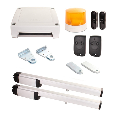
1Moteur x 2
2Bras moteur x 2
3Bras portail x 2
4Chape portail x 2
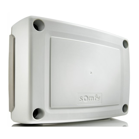
5Boitier électronique de commande x 1
6Capot moteur x 2
7Vis capot moteur x 4
8Carte information x 1
9Couvercle capot x 2
10 Vis couvercle x 4
11 Clé couvercle x 2
12 Vis boitier électronique x 1
13 Passe fil x 2
14 Serre cable x 4
15 Vis serre cable x 8
16 Vis de terre x 1
17 Rondelle de terre x 1
18 Rondelle 12 x 27 bride x 8
19 Vis axe / Bras moteur x 2
20 Axe court bras moteur / Bras portail x 2
21 Axe long bras portail / Chape x 2
22 Bague bras portail x 4
23 Amortisseur bras portail x 2
24 Télécommandes Keytis 4 RTS x 2
25 Antenne x 1
26 Strap cellule x 1
1
8
22
21
16
20
19
14 17
18
15
2
3
11
12
13
4
10
5
7
9
6
23
Composition du kit Composition of kit Samenstelling van de kit Composición del kit
2
1Motor x 2
2Motor arm x 2
3Gate arm x 2
4Gate fork x 2
5Electronic control box x 1
6Motor cover x 2
7Motor cover screw x 4
8Information card x 1
9Cover x 2
10 Cover screw x 2
11 Cover key x 2
12 Electronic box screw x 1
13 Grommet x 2
14 Cable clamp x 4
15 Cable clamp screw x 8
16 Earth screw x 1
17 Earth washer x 1
18 Clamp 12 x 27 washer x 8
19 Motor shaft / Arm screw x 2
20 Motor arm / Gate arm short shaft x 2
21 Gate / Fork arm long shaft x 2
22 Gate arm bushing x 4
23 Gate arm shock absorber x 2
24 Remote control Keytis 4 RTS x 2
25 Wire antenna x 1
26 Cell’s shunt x 1
1Motor x 2
2Motorarm x 2
3Arm hek x 2
4Hekbeugel x 2
5Elektronische besturingskast x 1
6Motorkap x 2
7Schroef motorkap x 4
8Informatiekaart x 1
9Deksel kap x 2
10 Schroef deksel x 2
11 Sleutel deksel x 2
12 Schroef besturingskast x 1
13 Kabeldoorvoer x 2
14 Kabelklem x 4
15 Schroef kabelklem x 8
16 Geaarde schroef x 1
17 Geaard ringetje x 1
18 Ringetje 12 x 27 flens x 8
19 Schroef as / Arm motor x 2
20 Korte as motorarm / Arm hek x 2
21 Lange as arm hek / Beugel x 2
22 Ring arm hek x 4
23 Schokbreker arm hek x 2
24 Handzender Keytis 4 RTS x 2
25 Antennedraad x 1
26 Brug cellen x 1
1Motor x 2
2Brazo de motor x 2
3Brazo de portón x 2
4Horquilla de portón x 2
5Caja electrónica de mando x 1
6Tapa del motor x 2
7Tornillo de la tapa del motor x 4
8Tarjeta de información x 1
9Cubierta de la tapa x 2
10 Tornillo de la cubierta x 2
11 Llave de la cubierta x 2
12 Tornillo de la caja electrónica x 1
13 Pasahilos x 2
14 Aprietacables x 4
15 Tornillo de aprietacables x 8
16 Tornillo de tierra x 1
17 Arandela de tierra x 1
18 Arandela 12 x 27 brida x 8
19 Tornillo de eje / Brazo de motor x 2
20 Eje corto de brazo de motor / Brazo de portón x 2
21 Eje largo de brazo de portón / Horquilla x 2
22 Anillo de brazo de portón x 4
23 Amortiguador de brazo de portón x 2
24 Emisor Keytis 4 RTS x 2
25 Cable de antena x 1
26 Conexión células x 1
24
25
26




2

1+ 2 Antenne
3 + 4 Jeu de cellules
3 + 5 Commande pour l’ouverture totale
3 + 6 Commande pour l’ouverture piétonne
3 + 7 Sortie permettant d’alimenter les accessoires (24Vdc / 12Vac)
8 + 9 Feu orange (sortie clignotante 24V 15 W maxi)
8 + 10 Gâche électrique selon cas spécifique.
11 + 12 Moteur 1 (24V)
13 + 14 Moteur 2 (24V)
15 + 16 Eclairage de zone (500W maxi en 230V)
17 + 18 Cable d’alimentation secteur 230V
 Description du boîtier électronique Electronic control box description Beschrijving elektronische besturingskast Descripción de la unidad electrónica
3

1+ 2 Antenna
3 + 4 Input for Photocell contacts
3 + 5 Control for total opening
3 + 6 Control for pedestrian opening
3 + 7 Output powering the accessories (24Vdc / 12Vac)
8 + 9 Flashing output for one orange light (24V - 15W)
8 + 10 Electric strike plate according to specific case
11 + 12 Motor 1 (24V)
13 + 14 Motor 2 (24V)
15 + 16 Area lighting output (500W maximum at 230V)
17 + 18 Power supply cable 230V

1+ 2 Antenne
3 + 4 Ingang voor foto-elektrische cellen
3 + 5 Bediening voor totale opening
3 + 6 Bediening voor voetgangersopening
3 + 7 Uitgang voeding voor accessoires (24 Vdc / 12 Vac)
8 + 9 Uitgang oranje waarschuwingslicht (24 V – 15 W)
8 + 10 elektrische (centrale) vergrendelingsplaat afhankelijk van specifiek geval
11 + 12 Motor 1 (24V)
13 + 14 Motor 2 (24V)
15 + 16 Uitgang verlichting (maximaal 500 W en 230 V)
17 + 18 Netvoedingskabel 230V

1+ 2 Antena
3 + 4
Entrada para el kit células fotoeléctricas
3 + 5
Orden para la abertura total
3 + 6
Orden para la abertura peatonal
3 + 7
Salida que permite alimentar los accesorios (24Vdc / 12Vac)
8 + 9
Salida luz intermitente, permite alimentar una luz naranja (24V – 15W)
8 + 10 Conexión eléctrica según caso específico
11 + 12 Motor 1 (24V)
13 + 14 Motor 2 (24V)
15 + 16
Salida de iluminación de zona (500W máximo en 230V)
17 + 18
Cable de alimentación
230V
3
L ≤ 2 m
H ≤ 2 m
P ≤ 200 Kg
166
 Vérifications avant le montage  Checking before assembly Toepassingsgebieden Verificaciones antes del montaje
4
Your gates must have end stops to limit their travel and their position is
determined by the opening angle (< or 120°). It is not necessary for the
two gates have the same angle of opening.
Bepaal de openingshoek van de hekdelen en bepaal op deze wijze de plaats
van de stoppers. De hoek mag niet groter zijn dan 120°. Het is niet nodig
dat de twee hekdelen dezelfde openingshoek hebben. Eén hekdeel kan
bijvoorbeeld tot 90° openen en het andere tot 120°.
Los batientes de la puerta deben ser detenidos por los topes con tal de
delimitar la carrera. El ángulo de apertura no debe exceder los 120°. No es
necessario que los batientes tengan el mismo angulo de apertura; por
ejemplo uno puede abrirse a 90° y el otro a 120°. El operador al efectuar
su autoaprendizaje, tendrá en cuenta de forma automática estos datos.
Cotas del operador (mm)
Overall dimensions (mm)
Afmetingen (mm)
Encombrement général (en mm)
Les piliers présentant un faux aplomb nécessitent l’utilisation d’une
platine spéciale. De même, quand l’un des trous de fixation des
pattes pilier est dans le vide ou proche de l’angle du mur, il est
impératif de positionner la platine support SOMFY.
Si le portail ne comporte pas de renforts, prévoir des contre-plaques
en métal (exemple: 15x15cm et 4mm d’épaisseur) pour la fixation des
équerres.
 If one of the attachment holes of the pillar anchors lies in space or
near the corner of a wall, then the SOMFY support plate provided as an
option must be used.
If your gates do not have reinforcement, it is necessary to provide
reinforcing plates for attaching the brackets ( a 15x15 cm metal
plate, 4mm thick for example).
- Bij te smalle pilaren kan U gebruik maken van speciale montageplaten
(niet meegeleverd) en hoeksteunen (niet meegeleverd), zoals getoond op de tekening.
- Indien uw draaihek geen horizontale dwarsbalken bezit, moeten
verstevigingen aangebracht worden, waarop de beugels gemonteerd
kunnen worden (bv. een metalen plaat van 15 x 15 cm / 4mm dik).
Pilares que presentan una falsa verticalidad, soportes irregulares:
utilice la placa soporte SOMFY. (accesorio)
Puerta sin refuerzos: es necesario instalar contraplacas para la
fijacion de los soportes (por ejemplo, una placa de metal de
15 x 15 cm con 4mm de espesor).
Ámbito de aplicación
Scope of application
Toepassingsgebied
Domaine d’application
Les vantaux doivent être arrêtés par des butées fixées solidement au sol
afin que leur course soit délimitée à l’ouverture comme à la fermeture.
L’emplacement de ces butées sera déterminé par l’angle d’ouverture des
vantaux (< ou = à 120°). L’angle d’ouverture des deux vantaux peut être
différent.
4
65 mm
65 mm
Par sécurité, verifier la distance D: distance entre l’axe AM et le 1er obstacle côté opposé au vantail (écoinçon) D ≥405 mm.
NB : La distance L doit être comprise entre 800 mm et 2000 mm. Si L<1250, l’utilisation d’un jeu de cellules photoélectriques
est obligatoire.
A(mm) αmax (°) B (mm)
0120 205
0110 160
0105 150
50 100 150
100 95 150
150 90 150
200 90 150
250 90 150
1
NB : Les valeurs indiquées ont été calculées pour la configuration présentée (axe des gonds et axe du vantail identique).
Dans le cas ou ces deux axes ne seraient pas identiques (gonds déportés), les valeurs d’angle d’ouverture maximum des
deux vantaux seront diminuées.
1-Mesurer la distance A(distance gonds pilier).
2-Se reporter au tableau et choisir la côte en fonction de l’angle d’ouverture souhaité.
3-Tracer l’axe AM sur le pilier en respectant la côte Bchoisie.
3
By safety, check distance B: distance between AM axis and the 1st obstacle on the side opposite the gate (corner piece)
D ≥405 mm.
NB: Distance L must range between 800 mm and 2000 mm, if L < 1250, you must use a set of photocells.
Controleer uit veiligheidsoverwegingen de afstand D: de afstand tussen de as AM en het eerste obstakel aan de zijde
tegenover het hekdeel (hoekverbinding) D > 405 mm.
NB: de afstand L moet tussen 800 mm en 2000 mm bedragen, indien L<1250, moet er verplicht een set foto-elektrische
cellen gebruikt worden.
Porseguridad, verificar la distancia D: distancia entre el eje AM y el 1er obstáculo del lado opuesto al batiente (rinconera)
D > 405 mm.
nota: la distancia L debe estar comprendida entre 800 mm y 2000 mm, si L < 1250, la utilización de un juego de células
fotoeléctricas es obligatoria.
 Processus de montage Assembly process Montageproces Proceso de montaje
5
2
NB: the values specified have been calculated for the configuration presented (identical hinge axes and gate axis). Should
these axes not be identical (offset hinges), the maximum opening angle values of both gates will be hidden.
1-Measure distance A(hinge-pillar distance).
2-Refer to the table, and choose size Baccording to the opening angle required.
3-MarktheAM axis on the pillar, while complying with the Bsize chosen.
NB: de aangegeven waarden zijn berekend voor de aangegeven configuratie (as van de hengsels en as van het hekdeel
zijn identiek). Indien deze twee assen niet identiek zijn (verschoven hengsels), moet de waarde van de maximale
openingshoek van beide hekdelen verminderd worden.
1-Meet de afstand A(afstand hengsels pijler).
2-Raadpleeg de tabel en kies de maat Baan de hand van de gewenste openingshoek.
3-Teken de as AM op de pijler en neem de gekozen maat Bdaarbij in acht.
Nota: Los valores indicados se han calculado para la configuración presentada (eje de los goznes y eje del batiente
idénticos). En caso de que estos dos ejes no fueren idénticos (goznes desplazados), los valores de ángulo de apertura
máxima de los dos batientes se disminuirían.
1-Medir la distancia A(distancia gozne pilar).
2-Remitirse al cuadro y elegir en función del ángulo de apertura deseado, la cota Bcorrespondiente.
3-Trazar el eje AM sobre el pilar respetando la cota Belegida.
5
Tracerun axe horizontal AH au milieu du renfort, perpendiculaire à l'axe de rotation du portail.
Prolonger cet axe sur le pilier jusqu'à l'intersection avec AM.
Placer le gabarit à l'intersection des 2 axes et percer.
PORTAILS SANS RENFORT : si le portail ne comporte pas de renfort, placer les moteurs a environ 1/3 de la hauteur des vantaux en partant du bas.
De plus il est nécessaire de prévoir des contre-plaques pour la fixation des chapes (par exemple une plaque de métal de 150 x 150 x 4 mm).
name
tel
namename
teltel
- Ouvrir le capot supérieur à l’aide de la clé spécifique.
- Dévisser les 2 vis du capot inférieur, le retirer.
- Fixer le moteur en vérifiant le niveau.
Carte info : Pour plus de visibilité, utiliser un feutre indélébile.
Mark an AH horizontal axis in the middle of the reinforcement, perpendicular to the gate's rotation axis.
Extend this axis on the pillar to the AM intersection.
Fit the template at the intersection of the 2 axes, and drill.
GATES WITHOUT REINFORCEMENTS: if the gate does not have reinforcements, fit the motors at about 1/3 of the height of the gates from the bottom.
In addition, plan to fit backplates for securing the forks (e.g. a metal plate 150x150x4 mm).
Trek een horizontale as AH in het midden van de versterking, loodrecht op de draaias van het hek.
Verleng deze as op de pijler tot de kruising met AM.
Plaats de mal op de kruising van de 2 assen en boor een gat.
HEKKEN ZONDER VERSTERKING: indien het hek geen versterking heeft, plaats dan de motoren op ongeveer 1/3 van de hoogte van de hekdelen,
van onderaf gemeten. Het is verder nodig voor ankerplaten te zorgen voor het bevestigen van de beugels (bijvoorbeeld een metalen plaat van 150 x 150 x 4 mm).
Trazarun eje horizontal AH en medio del refuerzo, perpendicular al eje de rotación del portón.
Prolongar este eje sobre el pilar hasta la intersección con AM.
Colocar la plantilla en la intersección de los 2 ejes y perforar.
PORTONES SIN REFUERZO: si el portón no incluye refuerzos, colocar los motores a aproximadamente 1/3 de la altura de los batientes partiendo de abajo.
Además, es necesario prever contraplacas para la fijación de las horquillas (por ejemplo una placa de metal de 150 x 150 x 4 mm).
- Open the upper cover using the specific key.
- Unscrew the 2 lower cover screws, remove it.
- Fit the motor while checking the level.
Info card: For more visibility, use a permanent ink.
- Open de bovenkap met behulp van de speciale sleutel.
- Draai de 2 schroeven van de onderkap los en neem deze uit.
- Bevestig de motor en controleer het peil met een waterpas.
Informatiekaart: Gebruik een onwisbare viltstift voor een beter zicht.
- Abrir la tapa superior con la ayuda de la llave específica.
- Desatornillar los 2 tornillos de la tapa inferior, retirarla.
- Fijar el motor verificando el nivel.
Tarjeta de información: Para mayorvisibilidad, utilizar un marcador permanente.
6
Assembler les bras sans utiliser d’outil afin de ne pas endommager les bagues.
Assemble the arms without using tools while preventing to damage the bushings.
Monteer de armen zonder gereedschap om de ringen niet te beschadigen.
Ensamblar los brazos sin utilizar herramientas para no dañar los anillos.
Déverrouiller le bras des moteurs à l’aide du bouton situé sur le dessus du moteur.
En position déverrouillée, les bras doivent être manoeuvrés lentement pour éviter la détérioration
des moteurs.
( Cadenas fermé: bras verrouillés; cadenas ouvert: fonctionnement manuel)
Unlock the motor arms using the knob located on the top of the motor.
In the unlocked position, handle the arms gently to prevent damaging the motors.
(Padlock closed: arms locked; padlock open: manual operation)
Ontgrendel de armen van de motoren met behulp van de knop bovenop de motor.
In de vergrendelde stand moeten de armen langzaam bewogen worden om beschadiging van de
motoren te voorkomen.
(Hangslot gesloten: armen vergrendeld; hangslot open: handmatige werking)
Desbloquear el brazo de los motores con la ayuda del botón situado en la parte superior del motor.
En posición desbloquear, los brazos se deben manipular lentamente para evitar el deterioro de
los motores.
(Candado cerrado: brazos bloqueados; candado abierto: funcionamiento manual)




7
Déplier les bras vers le portail, en les alignant avec le
moteur et le renfort du portail. Marquer les entraxes
pour la fixation des chapes sur le portail. Retirer les
bras, percer et fixer les chappes.
NB : avant de percer, vérifier que le bras est bien
horizontal.
Montage des passe-câbles sur les 2 moteurs.
M1 M2
Unfold the arms towards the gate, while aligning
them with the motor and gate reinforcement. Mark
the centre distances to fit the forks onto the gate.
Remove the arms, drill, and secure the forks.
NB: before drilling, check that the arm is horizontal.
Klap de armen naar het hek toe en zet ze op één
lijn met de motor en de versterking van het hek.
Geef de asafstanden aan voor het bevestigen van
de beugels op het hek. Verwijder de armen, boor
en bevestig de beugels.
NB: controleer vóór het boren of de arm goed
horizontaal staat.
Desplegar los brazos hacia el portón, alineándolos con
el motor y el refuerzo del portón. Marcar los entreejes
para la fijación de las horquillas sobre el portón.
Retirar los brazos, perforar y fijar las horquillas.
Nota: antes de perforar, verificar que el brazo
esté horizontal.
Fitting the cable grommets on the 2 motors.
Montage van de kabeldoorvoer over de 2 motoren.
Montaje de los pasacables en los 2 motores.