Sony UP-CX2 User manual

DIGITAL PHOTO PRINTER
UP-CX2
SERVICE MANUAL
1st Edition

UP-CX2
!警告
このマニュアルは,サービス専用です。
お客様が,このマニュアルに記載された設置や保守,点検,修理などを行うと感電や火災,
人身事故につながることがあります。
危険をさけるため,サービストレーニングを受けた技術者のみご使用ください。
!WARNING
This manual is intended for qualified service personnel only.
To reduce the risk of electric shock, fire or injury, do not perform any servicing other than that
contained in the operating instructions unless you are qualified to do so. Refer all servicing to
qualified service personnel.
!WARNUNG
Die Anleitung ist nur für qualifiziertes Fachpersonal bestimmt.
Alle Wartungsarbeiten dürfen nur von qualifiziertem Fachpersonal ausgeführt werden. Um die
Gefahr eines elektrischen Schlages, Feuergefahr und Verletzungen zu vermeiden, sind bei
Wartungsarbeiten strikt die Angaben in der Anleitung zu befolgen. Andere als die angegeben
Wartungsarbeiten dürfen nur von Personen ausgeführt werden, die eine spezielle Befähigung
dazu besitzen.
!AVERTISSEMENT
Ce manual est destiné uniquement aux personnes compétentes en charge de l’entretien. Afin
de réduire les risques de décharge électrique, d’incendie ou de blessure n’effectuer que les
réparations indiquées dans le mode d’emploi à moins d’être qualifié pour en effectuer d’autres.
Pour toute réparation faire appel à une personne compétente uniquement.

1 (E)
UP-CX2
Table of Contents
1-10. Cleaning ..................................................................1-34 (E)
1-10-1. Cleaning the Inside of the Printer ..................1-34 (E)
1-10-2. Cleaning the Printer Roller ............................1-37 (E)
1-10-3. Cleaning the Cabinet...................................... 1-37 (E)
1-10-4. Cleaning the Filter for
the Ventilation Holes......................................1-37 (E)
2. Adjustment
2-1. Operation during Replacement of Parts ....................2-1 (E)
2-2. Thermal Head............................................................2-2 (E)
2-2-1. Thermal Head Cleaning...................................2-3 (E)
2-2-2. Print of Test Pattern (16STEP) ........................2-4 (E)
2-2-3. Setting of Thermal Head Resistance Value...... 2-5 (E)
2-2-4. Position Adjustment.........................................2-6 (E)
2-2-5. Density Adjustment .........................................2-8 (E)
2-2-6. History Reset....................................................2-9 (E)
2-3. Ribbon Drive Assembly ..........................................2-10 (E)
2-3-1. Setting of Takeup Tension Ratio....................2-10 (E)
2-4. DC Fan (for Inside) ................................................. 2-11 (E)
2-5. MA-140 Board ........................................................ 2-11 (E)
2-5-1. Backup of Various Information Items............2-12 (E)
2-5-2. Write of Firmware..........................................2-14 (E)
2-5-3. Write of Backed Up Information Items .........2-15 (E)
2-5-4. Processing Required When Information
Items Cannot Be Backed Up.......................... 2-16 (E)
2-5-5. Setting of USB Serial Number.......................2-16 (E)
3. Mechanical Behavior Description
3-1. Mechanical Flow.......................................................3-1 (E)
3-2. Print Flow..................................................................3-2 (E)
3-3. Print ...........................................................................3-4 (E)
4. Circuit Description
4-1. System Control..........................................................4-1 (E)
4-2. Mechanical Control...................................................4-1 (E)
4-3. Power System............................................................4-2 (E)
Manual Structure
Purpose of this manual............................................................ 3 (E)
Related manuals...................................................................... 3 (E)
1. Service Overview
1-1. Precaution in Transportation of the Unit ................... 1-1 (E)
1-2. Board Location..........................................................1-1 (E)
1-3. Main Parts Location and Sensor Location ................1-2 (E)
1-4. Installing/Removing the Cabinet............................... 1-3 (E)
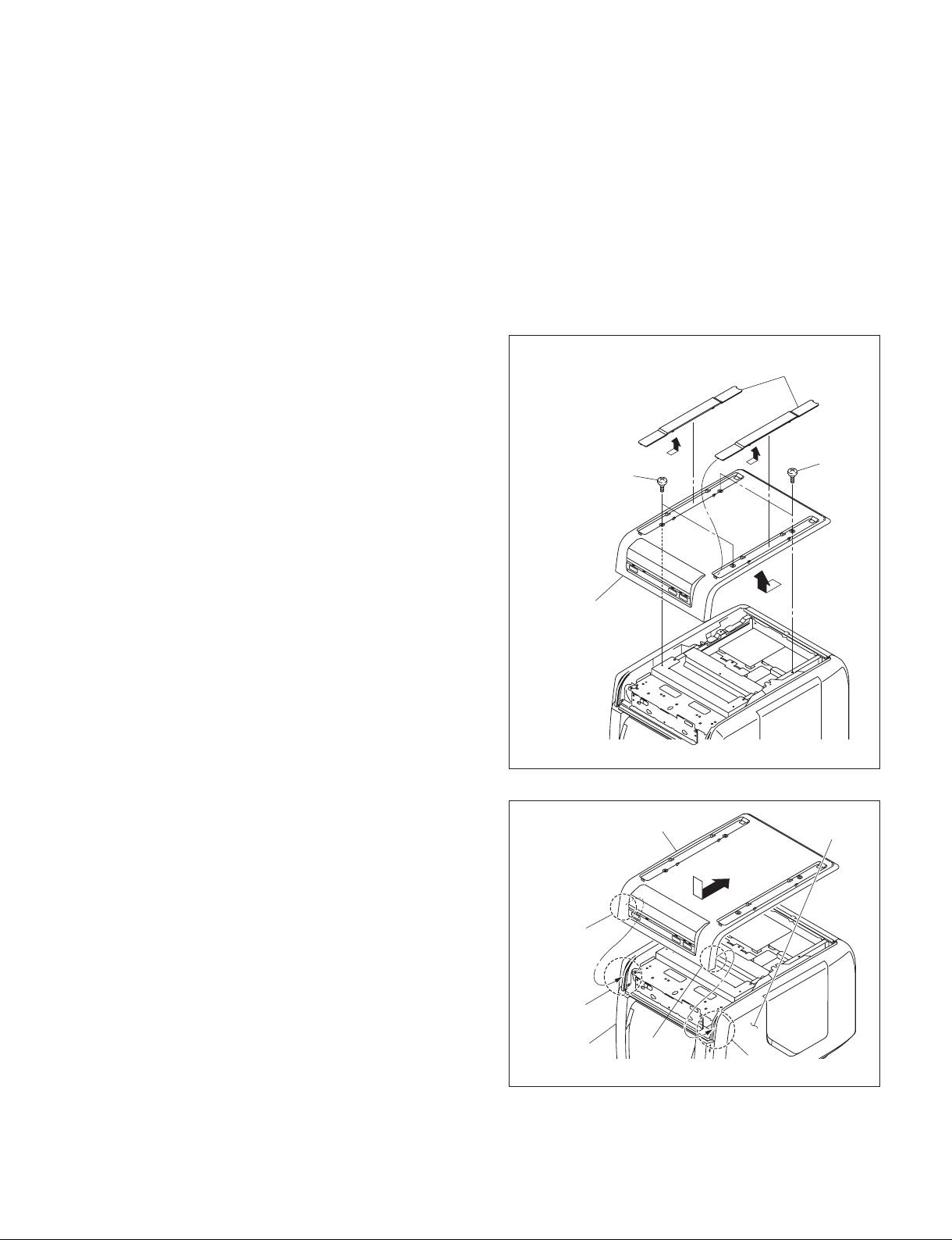
1-4-1. Top Panel (C2) Assembly ................................1-3 (E)
1-4-2. Side Panel (R) Assembly/Side Panel (L) ......... 1-4 (E)
1-4-3. Rear Panel (C1) Assembly...............................1-5 (E)
1-4-4. Inner Cover (Front) Assembly ......................... 1-5 (E)
1-4-5. Door Panel (C2) Assembly ..............................1-6 (E)
1-5. Replacing the Board..................................................1-7 (E)
1-5-1. MEC-33 Board.................................................1-7 (E)
1-5-2. MA-140 Board.................................................1-8 (E)
1-5-3. KY-617 Board..................................................1-9 (E)
1-5-4. SE-1056 Board.................................................1-9 (E)
1-6. Replacing the Main Parts ........................................ 1-10 (E)
1-6-1. Switching Regulator ......................................1-10 (E)
1-6-2. Ribbon Drive Assembly................................. 1-11 (E)
1-6-3. Ribbon (T) Motor Assembly/
Ribbon (S) Motor Assembly.......................... 1-12 (E)
1-6-4. Stepping Motor ..............................................1-14 (E)
1-6-5. Position Motor ............................................... 1-14 (E)
1-6-6. DC Fan (for Inside)........................................1-15 (E)
1-6-7. DC Fan (for Thermal Head)...........................1-16 (E)
1-6-8. Cutter Unit .....................................................1-17 (E)
1-6-9. Paper Eject Guide Assembly..........................1-18 (E)
1-6-10. Paper Drive Roller .........................................1-19 (E)
1-6-11. Platen Roller ..................................................1-21 (E)
1-6-12. Capstan Roller................................................1-22 (E)
1-6-13. Thermal Head ................................................1-24 (E)
1-6-14. Pinch Roller/Cam (L)/Cam (M)/Cam (R)...... 1-27 (E)
1-6-15. Filter...............................................................1-30 (E)
1-7. Lead-free Solder......................................................1-31 (E)
1-8. Recommended Power Cord..................................... 1-32 (E)
1-9. Periodical Replacement Recommended Parts......... 1-33 (E)

2 (E) UP-CX2
5. Service Mode
5-1. Preparation ................................................................5-1 (E)
5-1-1. Required Equipment ........................................5-1 (E)
5-1-2. Installing the Driver.........................................5-1 (E)
5-2. Start ...........................................................................5-2 (E)
5-3. Service Tool Menus...................................................5-3 (E)
5-3-1. Configuration ...................................................5-3 (E)
5-3-2. Diag Menu ....................................................... 5-4 (E)
5-3-3. System Info Menu............................................5-7 (E)
5-3-4. Error Log Menu ...............................................5-8 (E)
5-3-5. Export/Import Menu ........................................5-9 (E)
5-3-6. Setting Menu..................................................5-10 (E)
6. Troubleshooting
6-1. Procedure Before and After Repair ...........................6-1 (E)
6-2. Upgrading of Firmware and Download of
Printer Driver.............................................................6-1 (E)
6-3. Printing Image Defects.............................................. 6-2 (E)
6-4. Error Display.............................................................6-3 (E)
6-4-1. Error List of the Indicator Lighting .................6-3 (E)
6-4-2. Error List Recorded in Error Log ....................6-6 (E)
7. Spare Parts
7-1. Notes on Repair Parts...................................................... 7-1
7-2. Exploded Views............................................................... 7-2
7-3. Packing Materials & Supplied Accessories................... 7-24
8. Diagrams
8-1. Block Diagrams............................................................... 8-1
Overall............................................................................. 8-1
8-2. Frame Wiring................................................................... 8-2
Frame Wiring................................................................... 8-2

3 (E)
UP-CX2
Manual Structure
Purpose of this manual
This manual is the service manual of Digital Photo Printer UP-CX2.
This manual describes the information on service such as service overview, adjust-
ment, mechanical behavior description, circuit description, service mode, trouble-
shooting, spare parts, block diagrams, and frame wiring.
The service of this unit is basically performed by the replacement of board.
Therefore, the schematic diagram, board layout and electrical parts list are not
contained.
Related manuals
In addition to this “Service Manual”, this unit is provided with the manual below.
.“Operating Instructions” PDF
(Included in the CD-ROM Supplied for products.)
These manuals describes the information required for the actual management and
operation of this unit.


1-1 (E)
UP-CX2
Section 1
Service Overview
HP-131 board
MA-140 board
MEC-33 board
RM-208 board
SE-840 board
SU-114 board
KY-617 board
RM-210 board
RM-207 board
RM-209 board
PE-44 board
PE-43 board
PSW-87 board
PE-42 board
SE-1056 board
CT-267 board
SU-115 board CT-268 board
SU-113 board
CT-266 board
Cutter unit
Paper eject guide assembly
Return guide assembly
1-1. Precaution in Transportation of the Unit
.When transporting this unit, remove the ink ribbon and print paper from the unit.
.Be sure to remove the paper cassette assembly in the paper cassette before transporting. When trans-
porting within the paper cassette assembly, it may cause the printer error or jamming at starting to slip
the paper remnants into the cutter unit, paper eject guide assembly, or return guide assembly.
1-2. Board Location

1-2 (E) UP-CX2
1-3. Main Parts Location and Sensor Location
Ribbon (T) motor
Switching regulator
Thermal head
DC fan
(for inside)
DC fan
(for thermal head)
Ribbon (S) motor
Ribbon
FG sensor
Position sensor
1-wire
sensor
PP mode1, 2
sensor
Stepping
motor
Head position motor
Cutter unit
Ribbon (Y) start mark
sensor
Ribbon (MCL)
start mark
sensor
PE sensor
PJ sensor
Paper FG
sensor

1-3 (E)
UP-CX2
Top covers
AA
B
Top panel (C2)
assembly
Stepped
screws
Stepped screws
Top panel (C2) assembly
Side panel
Side panel
Portion A
Portion B
Portion A
Portion B
1-4. Installing/Removing the Cabinet
n
Tighten the screw with the torque below.
Tighten torque:
.Stepped screw 0.80 ?0.05 N.m
1-4-1. Top Panel (C2) Assembly
1. Remove the two top covers in the direction of the
arrow A.
2. Remove the four stepped screws, then remove the top
panel (C2) assembly in the direction of the arrow B.
3. To install, reverse the removal procedure.
m
.When attaching the top panel (C2) assembly, be
careful not to catch the harness.
.When attaching the top panel (C2) assembly, be sure
to securely hook the portions A of the top panel (C2)
assembly on the portions B of the side panel.

1-4 (E) UP-CX2
Stepped screw
Side panel (L)
Hook
Hook
Stepped screw
AB
Side panel (R) assembly
Door panel assembly Hooks
1-4-2. Side Panel (R) Assembly/Side Panel (L)
1. Remove the top panel (C2) assembly. (Refer to Section 1-4-1.)
2. Open the door panel assembly in the direction of the
arrow A.
3. Remove the stepped screw and two hooks, then re-
move the side panel (R) assembly in the direction of
the arrow B.
4. Remove the stepped screw and two hooks, then re-
move the side panel (L) in the direction of the arrow.
5. To install, reverse the removal procedure.

1-5 (E)
UP-CX2
Rear panel (C1) assembly
Stepped screws
Stepped
screws
Inner cover (front)
assembly
Bottom chassis
assembly
Stepped
screws
Portions A
Holes
1-4-3. Rear Panel (C1) Assembly
1. Remove the top panel (C2) assembly. (Refer to Section 1-4-1.)
2. Remove the four stepped screws, then remove the rear
panel (C1) assembly.
3. To install, reverse the removal procedure.
1-4-4. Inner Cover (Front) Assembly
1. Remove the top panel (C2) assembly. (Refer to Section 1-4-1.)
2. Remove the side panel (R) assembly and side panel (L). (Refer to Section 1-4-2.)
3. Remove the two stepped screws.
4. Remove the two portions A from the two holes of the
bottom chassis assembly, then remove the inner cover
(front) assembly.
5. To install, reverse the removal procedure.

1-6 (E) UP-CX2
Door fulcrum plate
subassembly
Door panel (C2)
assembly
Shaft
Door fulcrum plate
subassembly
Shaft
1-4-5. Door Panel (C2) Assembly
1. Remove the top panel (C2) assembly. (Refer to Section 1-4-1.)
2. Remove the side panel (R) assembly and side panel (L). (Refer to Section 1-4-2.)
3. Remove the inner cover (front) assembly. (Refer to Section 1-4-4.)
4. Remove the door panel (C2) assembly from the two
shafts of the door fulcrum plate subassemblies in the
direction of the arrow.
5. To install, reverse the removal procedure.

1-7 (E)
UP-CX2
Flexible flat
cable
MEC-33 board
Harnesses
MEC-33 board (Side A)
CN101
CN301
CN300
CN103
CN100
CN102
CN200
CN202
CN203
CN302
CN401
CN400
CN411
CN406
CN405
CN402CN404
CN403
BVTT3 x6
1-5. Replacing the Board
n
Tighten the each screw with the torque below.
Tighten torque:
.BVTT3 x6 0.80 ?0.05 N.m
.PS3 x4 0.80 ?0.05 N.m (For USB connector, 0.60 ?0.05 N.m)
1-5-1. MEC-33 Board
1. Remove the top panel (C2) assembly. (Refer to Section 1-4-1.)
2. Disconnect all harnesses and flexible flat cables from
the connectors on the MEC-33 board.
3. Remove the four screws, then remove the MEC-33
board in the direction of the arrow.
4. To install, reverse the removal procedure.

1-8 (E) UP-CX2
BVTT3 x6
PS3 x4
MA-140 board (Side A)
MA-140 board
CN600
CN603
CN301 CN601 Flexible flat
cable
Flexible flat
cables
Harness
1-5-2. MA-140 Board
n
When replacing the MA-140 board, the adjustment and the firmware version upgrade are required.
Before replacement, be sure to refer to “Operation during Replacement of Parts” in Section 2-1, and
Section 2-5.
1. Remove the top panel (C2) assembly. (Refer to Section 1-4-1.)
2. Remove the rear panel (C1) assembly. (Refer to Section 1-4-3.)
3. Remove the screw (PS3 x4).
4. Disconnect all harnesses and flexible flat cables from
the connectors on the MA-140 board.
5. Remove the three screws (BVTT3 x6), then remove
the MA-140 board.
6. To install, reverse the removal procedure.

1-9 (E)
UP-CX2
Harness
KY-617 board
CN1
CN3
Flexible flat cable
BVTT
3x6
BVTT
3x6
BVTT
3x6
SE-1056 board
FG bracket
Paper drive FG
Harness
1-5-3. KY-617 Board
1. Remove the top panel (C2) assembly. (Refer to Section 1-4-1.)
2. Disconnect the harness and flexible flat cable from the
connectors (CN1 and CN3) on the KY-617 board.
3. Remove the three screws, then remove the KY-617
board.
4. To install, reverse the removal procedure.
1-5-4. SE-1056 Board
1. Remove the top panel (C2) assembly. (Refer to Section 1-4-1.)
2. Remove the side panel (R) assembly. (Refer to steps 1 to 3 in Section 1-4-2.)
3. Disconnect the harness from the connector on the
SE-1056 board.
4. Remove the screw, then remove the FG bracket in the
direction of the arrow.
n
When removing the FG bracket, be careful not to
damage the paper drive FG.
5. Remove the screw, then remove the SE-1056 board.
6. To install, reverse the removal procedure.

1-10 (E) UP-CX2
Harnesses
Harness
MEC-33 board
Switching
regulator Power supply
mounting bracket
PSW cover
CN501
CN701
CN702
CN300
BVTT
3x6
BVTT
3x6
BVTT
3x6
PSW
3 x 6
1-6. Replacing the Main Parts
n
Tighten the each screw with the torque below.
Tighten torque:
.BVTT3 x6 0.80 ?0.05 N.m
.BVTT3 x10 0.80 ?0.05 N.m
.PS2.6 x5 0.50 ?0.03 N.m
.PS3 x4 0.80 ?0.05 N.m
.PSW3 x6 0.80 ?0.05 N.m
.PSW3 x12 0.80 ?0.05 N.m
1-6-1. Switching Regulator
1. Remove the top panel (C2) assembly. (Refer to Section 1-4-1.)
2. Remove the side panel (R) assembly and side panel (L). (Refer to Section 1-4-2.)
3. Remove the rear panel (C1) assembly. (Refer to Section 1-4-3.)
4. Remove the screw (BVTT3 x6), then remove the
PSW cover.
5. Disconnect the harness from the connector (CN300) on
the MEC-33 board.
6. Disconnect the two harnesses from the connectors
(CN701 and CN702) on the switching regulator.
7. Remove the four screws (BVTT3 x6), then remove
the power supply mounting bracket.
8. Remove the two screws (PSW3 x6) and disconnect
the harness from the connector (CN501) on the switch-
ing regulator, then remove the switching regulator.
9. To install, reverse the removal procedure.
n
When attaching the switching regulator, be careful not
to catch the harness.

1-11 (E)
UP-CX2
Ribbon drive
assembly
Binding bands
Label
Harnesses
Ribbon tension roller
Main chassis
Hole
Ribbon drive assembly
Clamper
Ribbon drive
assembly
Ribbon drive assembly
MEC-33
board
Clamper
BVTT
3x6
Harness
Harness
CN200
CN403
CN401
CN1
HP-131 board
1-6-2. Ribbon Drive Assembly
m
.When the ribbon drive assembly is replaced, it is required to set the ratio of the takeup tension.
For details, refer to “Operation during Replacement of Parts” in Section 2-1, and Section 2-3.
.When replacing to the new ribbon drive assembly, take a note of the three-digit value (Example: 1.54)
of C in the lowest line on the label which applied as shown in the figure before replacement.
1. Remove the top panel (C2) assembly. (Refer to Section 1-4-1.)
2. Remove the side panel (L). (Refer to step 4 in Section 1-4-2.)
3. Cut the two binding bands placed in the upper portion of the ribbon drive assembly.
4. Remove the harness from the two clampers.
5. Disconnect the four harnesses from the connectors (CN200, CN401, and CN403) on the MEC-33
board and the connector (CN1) on the HP-131 board.
6. Remove the five screws, then remove the ribbon drive assembly.
n
When removing/installing the ribbon drive assembly, take care not to catch the ribbon tension roller
with the hole on the main chassis.
7. To install, reverse the removal procedure.
nWhen attaching the ribbon drive assembly, be careful not to catch the harness.

1-12 (E) UP-CX2
Helical extension
spring
Ribbon (S) motor assembly
SE-840 board
Rewind motor
bracket assembly
Pad holder (B)
subassembly
SU-115 board
Stay (R)
subassembly
Helical extension spring
PS
3x4
BVTT3 x6
BVTT3 x6
BVTT3 x 6
BVTT3 x6
BVTT
3x6
W2.3
W2.3
Solders
Ribbon bracket
retaining assembly
1-6-3. Ribbon (T) Motor Assembly/Ribbon (S) Motor Assembly
1. Remove the top panel (C2) assembly. (Refer to Section 1-4-1.)
2. Remove the side panel (L). (Refer to step 4 in Section 1-4-2.)
3. Remove the ribbon drive assembly. (Refer to Section 1-6-2.)
4. Remove the snap ring (W2.3) and screw (BVTT3 x6), then remove the stay (R) subassembly.
5. Remove the screw (BVTT3 x6), then remove the SE-840 board.
6. Remove the two helical extension springs and two screws (BVTT3 x6), then remove the ribbon
bracket retaining assembly.
7. Remove the snap ring (W2.3), then remove the pad holder (B) subassembly.
8. Remove the two screws (BVTT3 x6), then remove the rewind motor bracket assembly.
9. Remove the two screws (PS3 x4), then remove the ribbon (S) motor assembly.
10. Unsolder the two pins, then remove the SU-115 board.

1-13 (E)
UP-CX2
W2.3
E4.0
Worm wheel (R)
Pendulum
assembly (S)
Pendulum
assembly (L)
Idler gear (R)
Ribbon (T) motor assembly
SU-113 board
Solders
PS2.6 x5
Approx. 1 cm
(0.4 inches)
Shaft Ribbon (T) motor assembly
Grease an entire loop of the gear portion of the
ribbon (T) motor assembly.
(approx. 1 cm (0.4 inches) width area centering
around the shaft.)
Grease an entire loop of the gear portion of the
ribbon (S) motor assembly.
(approx. 1 cm (0.4 inches) width area centering
around the hole.)
Approx. 1 cm
(0.4 inches)
Hole
Ribbon (S) motor assembly
11. Remove the snap ring (W2.3), then remove the pendulum assembly (S), idler gear (R), and pendulum
assembly (L).
12. Remove the snap ring (E4.0), then remove the worm wheel (R).
13. Remove the two screws (PS2.6 x5), then remove the ribbon (T) motor assembly.
14. Unsolder the two pins, then remove the SU-113 board.
15. To install, reverse the removal procedure.
n
When installing the ribbon (T) motor assembly and ribbon (S) motor assembly, grease the specified
grease as shown in the figure.
Parts No.: 7-651-000-11
Name: Sony grease SGL-801

1-14 (E) UP-CX2
Timing belt
Stepping motor bracket
Stepping motor
Helical
extension
spring
Harness
PS
3x4
BVTT
3x6
DC motor bracket
Position
motor
Position motor
PS
2.6 x 5
BVTT
3 x 6
SU-114 board
Solders
Grease an entire loop of the gear
portion of the position motor.
1-6-4. Stepping Motor
1. Remove the top panel (C2) assembly. (Refer to Section 1-4-1.)
2. Remove the side panel (L). (Refer to step 4 in Section 1-4-2.)
3. Remove the ribbon drive assembly. (Refer to Section 1-6-2.)
4. Remove the helical extension spring and three screws
(BVTT3 x6), then remove the stepping motor bracket
from the timing belt.
n
Take care not to damage the timing belt. If damaged, it
may cause the out of joint.
5. Remove the three screws (PS3 x4), then remove the
stepping motor.
6. Disconnect the harness from the stepping motor.
7. To install, reverse the removal procedure.
1-6-5. Position Motor
1. Remove the top panel (C2) assembly. (Refer to Section 1-4-1.)
2. Remove the side panel (L). (Refer to step 4 in Section 1-4-2.)
3. Remove the three screws (BVTT3 x6), then remove
the DC motor bracket.
4. Remove the two screws (PS2.6 x5), then remove the
position motor.
5. Unsolder the two pins, then remove the SU-114 board.
6. To install, reverse the removal procedure.
n
When installing the position motor, grease the speci-
fied grease as shown in the figure.
Parts No.: 7-651-000-11
Name: Sony grease SGL-801
Other manuals for UP-CX2
1
Table of contents
Other Sony Printer manuals

Sony
Sony UPA-50RH User manual

Sony
Sony OEP-4 User manual

Sony
Sony FVP-1/1E User manual

Sony
Sony UP-880 User manual

Sony
Sony UP-980 User manual

Sony
Sony UP-D2550S User manual

Sony
Sony DPP-MS300 Marketing User manual

Sony
Sony UP-CX1 series User manual

Sony
Sony SNAPLAB UP-CR20L User manual

Sony
Sony UPX-C200 User manual

Sony
Sony UPD-X100 User manual

Sony
Sony DPP-MS300 Marketing User manual

Sony
Sony DPP-FP30 Fall 2005 User manual

Sony
Sony PIX1L User manual

Sony
Sony DPP-FP97 User manual

Sony
Sony SnapLab UP-CR15L Instruction manual

Sony
Sony UP-51MD User manual

Sony
Sony UP-DF500 User manual

Sony
Sony Digital Photo Printer DPP-EX7 User manual

Sony
Sony DPP-SV88 User manual