Sony OEP-4 User manual

COLOR VIDEO PRINTER
OEP-4
SERVICE MANUAL
Volume 2 1st Edition

OEP-4
!WARNING
This manual is intended for qualified service personnel only.
To reduce the risk of electric shock, fire or injury, do not perform any servicing other than that
contained in the operating instructions unless you are qualified to do so. Refer all servicing to
qualified service personnel.
!WARNUNG
Die Anleitung ist nur für qualifiziertes Fachpersonal bestimmt.
Alle Wartungsarbeiten dürfen nur von qualifiziertem Fachpersonal ausgeführt werden. Um die
Gefahr eines elektrischen Schlages, Feuergefahr und Verletzungen zu vermeiden, sind bei
Wartungsarbeiten strikt die Angaben in der Anleitung zu befolgen.Andere als die angegeben
Wartungsarbeiten dürfen nur von Personen ausgeführt werden, die eine spezielle Befähigung
dazu besitzen.
!AVERTISSEMENT
Ce manual est destiné uniquement aux personnes compétentes en charge de l’entretien.Afin
de réduire les risques de décharge électrique, d’incendie ou de blessure n’effectuer que les
réparations indiquées dans le mode d’emploi à moins d’être qualifié pour en effectuer d’autres.
Pour toute réparation faire appel à une personne compétente uniquement.

1
OEP-4
/Table of Contents
............................................................................3 (J)
....................................................................3 (J)
.........................................................................3 (J)
Manual Structure
Purpose of this manual ...........................................................3 (E)
Related manuals .....................................................................3 (E)
Trademarks .............................................................................3 (E)
1. Spare Parts
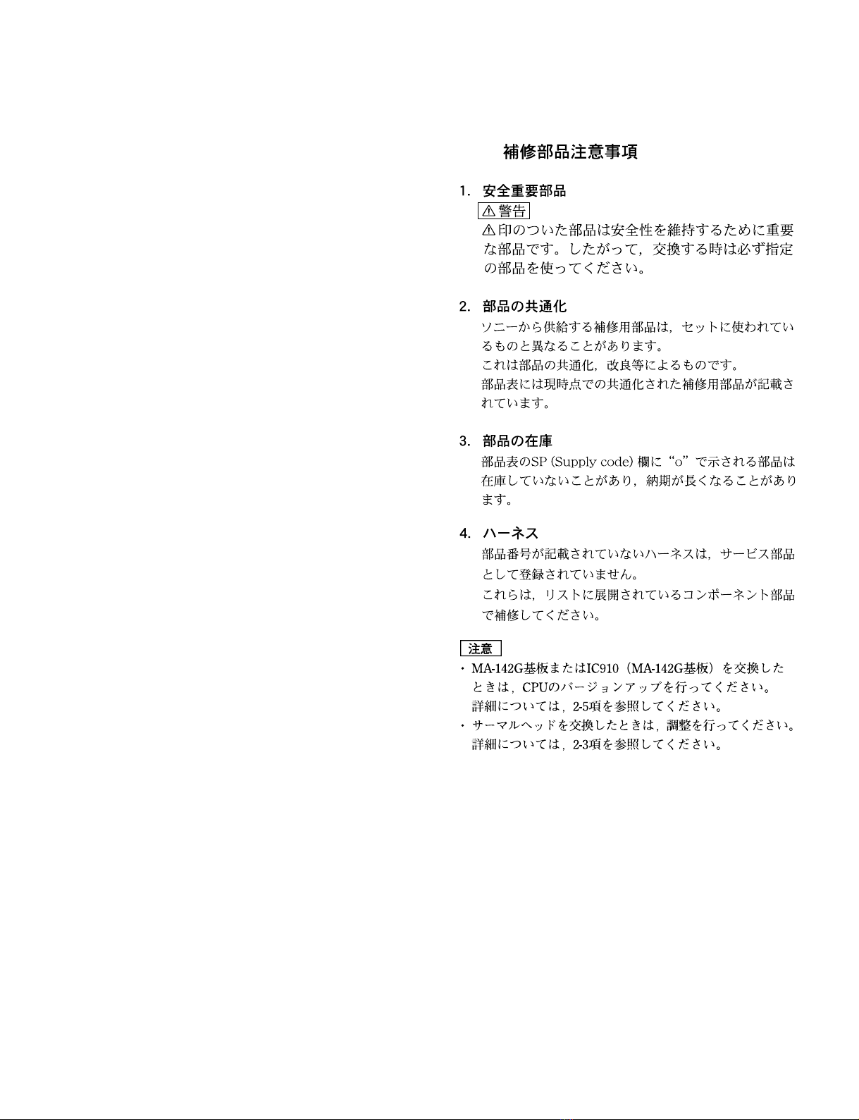
1-1. Notes on Repair Parts .....................................................1-1
1-1. .......................................................1-1
1-2. Exploded Views ..............................................................1-2
1-3. Electrical Parts List.......................................................1-20
1-4. Supplied Accessories ....................................................1-42
2. Block Diagram
Overall ............................................................................2-1
3. Schematic Diagrams
CCM-53G .......................................................................3-2
DP-407G .........................................................................3-3
EX-970............................................................................3-3
IF-988G...........................................................................3-4
IF-990G...........................................................................3-4
IF-989G...........................................................................3-5
KY-582G ........................................................................3-6
MA-142G........................................................................3-7
MEC-24G .....................................................................3-25
SE-746 ..........................................................................3-27
SE-747 ..........................................................................3-27
SE-748 ..........................................................................3-27
SE-749 ..........................................................................3-27
SE-750 ..........................................................................3-27
SE-751 ..........................................................................3-27
SE-752 ..........................................................................3-28
SE-753 ..........................................................................3-28
SE-754 ..........................................................................3-28
SE-755 ..........................................................................3-28
SE-756 ..........................................................................3-28
SE-762 ..........................................................................3-28
SU-84 ............................................................................3-29
SU-85 ............................................................................3-29
SU-86 ............................................................................3-29
SU-87 ............................................................................3-29
SW-1200 .......................................................................3-29
Frame Wiring ................................................................3-30
4. Board Layouts
CCM-53G .......................................................................4-2
DP-407G .........................................................................4-2
SW-1200 .........................................................................4-2
EX-970............................................................................4-3
IF-988G...........................................................................4-3
IF-990G...........................................................................4-3
IF-989G...........................................................................4-4
KY-582G ........................................................................4-4
MA-142G........................................................................4-5
MEC-24G .......................................................................4-6
SE-746 ............................................................................4-7
SE-747 ............................................................................4-7
SE-748 ............................................................................4-7
SE-749 ............................................................................4-7
SE-750 ............................................................................4-7
SE-751 ............................................................................4-7
SE-752 ............................................................................4-8
SE-753 ............................................................................4-8
SE-754 ............................................................................4-8
SE-755 ............................................................................4-8
SE-756 ............................................................................4-8
SE-762 ............................................................................4-9
SU-84 ..............................................................................4-9
SU-85 ..............................................................................4-9
SU-86 ..............................................................................4-9
SU-87 ..............................................................................4-9


3 (J)
OEP-4


3 (E)
OEP-4
Purpose of this manual This manual is the service manual Vol. 2 of Color Video Printer OEP-4.
This manual describes the information on maintenance and the service information
such as spare parts, block diagrams, schematic diagrams, and board layouts.
Related manuals In addition to this “Service Manual Vol. 2”, this unit is provided with the manual
below.
..
..
.Service Manual Vol. 1 (Not supplied for products.)
Part No.: 9-879-989-1X
This manual describes the information on the maintenance of this unit, and the
service overview, electrical alignment, troubleshooting, and location and fuctions
of sensors, motors, and mechanical parts.
..
..
.Operating Instruction (Supplied for products.)
Part No.: 2-638-113-1X
These manuals describes the information required for the actual management and
operation of this unit.
..
..
.“Semiconductor Pin Assignments” CD-ROM (Available on request)
This “Semiconductor Pin Assignments” CD-ROM allows you to search for
semiconductors used in Broadcast and Professional equipment.
Part number: 9-968-546-XX
Trademarks Trademarks and registered trademarks used in this manual are follows.
.Memory Stick is a registered trademark of SONY Corporation.
Other system names, product names, and company names appearing in this manual
are trademarks or registered trademarks of their respective holders.
Manual Structure


1-1
OEP-4
Section 1
Spare Parts
1-1.1-1. Notes on Repair Parts
1. Safety Related Components Warning
w
Components marked !are critical to safe operation.
Therefore, specified parts should be used in the case of
replacement.
2. Standardization of Parts
Some repair parts supplied by Sony differ from those
used for the unit. These are because of parts common-
ality and improvement.
Parts list has the present standardized repair parts.
3. Stock of Parts
Parts marked with “o” at SP (Supply Code) column of
the spare parts list may not be stocked. Therefore, the
delivery date will be delayed.
4. Harness
Harnesses with no part number are not registered as
spare parts.
In need of repair, get components shown in the list and
repair using them.
m
.When replacing the MA-142G board or IC910 (MA-
142G board), perform the firmware version upgrade.
For detail, refer to Section 2-5.
.When replacing the thermal head, perform the
adjustment.
For detail, refer to Section 2-3.

1-2 OEP-4
1-2. Exploded Views
Cover Block
BVTT
2.6 x5
BVTT
2.6 x5
BVTT
2.6 x5
BVTT
2.6 x5
BVTT
2.6 x5
A
A
C
C
B
B
PSW3 x6
1
6
2
5
5
3
10
11
12
13
4
15
14
9
816
7
7
7
7
M2.5

1-3
OEP-4
Cover Block
No. Part No. SP Description
1 A-1169-817-A s MOUNTED CIRCUIT BOARD, MA-142(O)G
2 X-3704-725-1 s ASSY, TOP COVER(O)
3 1-500-112-11 s BEAD, FERRITE
4 1-500-204-11 s CORE, FERRITE
5 3-642-920-02 s FOOT
6 3-990-302-01 s MINI FLAT CABLE CLAMP
7 4-031-617-22 s SCREW, M3 CASE STOPPER
8 3-903-976-01 s GASKET(230)
9 3-854-562-03 s STAY,CHASSIS
10 3-991-457-01 s HOLDER,CORE(L)
11 1-962-976-12 s HARNESS BOTTOM
12 1-963-937-11 s HARNESS, SUB (POWER-MA(PNX))
13 1-963-938-11 s HARNESS, SUB (POWER-MA(DM))
14 1-963-939-11 s HARNESS, SUB (MA-PANEL)
15 3-991-459-01 s HOLDER, CORE(S)
16 1-962-965-12 s HARNESS MA(D)-MEC(P)
7-682-947-01 s SCREW +PSW 3X6
7-685-861-01 s SCREW +BVTT 2.6X5 (S)

1-4 OEP-4
Front Panel Block
PSW
2.6 x8
PSW
2.6 x8
BVTT
2 x10
M2 x5
M2 x5
104
115
115
103
115 107
102
122
122
115
108
115
105
111
113
120
111
114
106
115
109
118
116
121
119
112
110
101
115
117

1-5
OEP-4
Front Panel Block
No. Part No. SP Description
101 A-1059-658-A s MOUNTED CIRCUIT BOARD, SE-756
102 A-1159-069-A s MOUNTED CIRCUIT BOARD, DP-407G
103 A-1159-070-A s MOUNTED CIRCUIT BOARD, KY-582G
104 X-3704-723-1 s DOOR(O) ASSY, RIBBON
105 X-3704-726-1 s COVER(O) ASSY, DOOR
106 X-3704-826-1 s COVER(O) ASSY, MS
107 1-831-093-11 s CABLE, FLEXIBLE FLAT (20 CORE)
108 1-831-097-11 s CABLE, FLEXIBLE FLAT (22 CORE)
109 3-022-410-01 s DAMPER
110 3-669-596-01 s WASHER (2.3), STOPPER
111 3-736-779-21 s MAGNET
112 3-854-574-01 s GEAR, DAMPER
113 3-854-575-11 s LEVER(RIBBON)
114 3-986-620-01 s PANEL, FRONT(O)
115 4-951-620-62 s SCREW (2.6)
116 3-854-568-02 s PLATE,PROTECTION
117 3-854-570-02 s BRACKET(SW)
118 X-3608-880-1 s DAMPER ASSY
119 3-854-585-01 s PLATE,SWITCH
120 3-854-584-01 s SPRING(RIBBON)
121 3-854-758-01 s SPRING(B)
122 X-3608-879-1 s FULCRUM ASSY
7-621-759-65 s +PSW, 2.6X8
7-685-855-01 s +BVTT 2X10 (S)

1-6 OEP-4
LW6
N6
BVTT
2.6 x5
BVTT
2.6 x5
BVTT
2.6 x5
BVTT
2.6 x5
BVTP
3 x8
BVTP
3 x8
BVTT
2.6 x5
BVTT
2.6 x5
PS3 x6
PS3 x6
BVTT
2.6 x5
BVTT
2.6 x5
BVTT
2.6 x5
PSW
4 x8
A
B
D
D
B
A
BVTT
2.6 x5
PS3 x 10
PS3 x 10
C
E
F
F
E
NDX-H005(SYM)
C
BVTT
2.6 x5
BVTT
2.6 x5
BVTT
2.6 x5
BVTT
2.6 x5
PS3 x6 PS
3 x6
BVTT
2.6 x5
G
H
G
H
213
224
214
202 231
216
237
208
223
201
222
235
228
227
230
233
225
211
209
217
212
219
215
226
207
205
234
229
210
232
218
204
221
203
206
236
220
Chassis Block

1-7
OEP-4
Chassis Block
No. Part No. SP Description
201 A-1059-666-A s MOUNTED CIRCUIT BOARD, SW-1200
202 A-1159-071-A s MOUNTED CIRCUIT BOARD, IF-988G
203 A-1159-072-A s MOUNTED CIRCUIT BOARD, IF-989G
204 A-1159-073-A s MOUNTED CIRCUIT BOARD, IF-990G
205
!
1-251-373-11 s INLET, AC
206
!
1-468-611-12 s REGULATOR, SWITCHING
207 1-543-982-12 s CORE, FERRITE
208 1-787-185-21 s D.C. FAN
209 1-831-094-11 s CABLE, FLEXIBLE FLAT (40 CORE)
210 1-831-095-11 s CABLE, FLEXIBLE FLAT (18 CORE)
211 1-831-096-11 s CABLE, FLEXIBLE FLAT (20 CORE)
212 3-660-004-01 o STOPPER, ROD
213 3-669-596-01 s WASHER (2.3), STOPPER
214 3-854-561-02 s GUIDE, PAPER(B)
215 3-854-588-01 s EDGING(CE)
216 3-986-622-01 s BUTTON, POWER(O)
217 3-990-271-01 s COVER, POWER SWITCH
218 3-990-273-01 s TERMINAL, P.E.
219 4-951-620-62 s SCREW (2.6)
220 X-3704-692-1 s ASSY,PLATE SHELD(A)
221 1-962-964-11 s HARNESS POWER-HEAD
222
!
1-963-026-11 s SUB HARNESS
223 3-854-555-01 s ROD,POWER SWITCH
224 3-854-556-01 s SCREW,COVER
225 3-854-558-01 s SPRING,COMPRESSION(ROD)
226 3-854-559-03 s COVER,CHASSIS
227 3-854-563-02 s STAY,BOTTOM(L)
228 3-854-565-01 s STAY,BOTTOM(R)
229 3-854-566-03 s STAY,TOP(R)
230 3-854-806-01 s SHIELD PLATE,MA
231 3-869-990-01 s BRACKET,MS
232 3-869-992-02 s BRACKET,REMOTE
233 3-872-899-01 s EDGING(CE)
234 3-986-619-03 s PANEL,REAR(O)
235 3-990-272-01 s BARRIER,POWER SWITCH
236 3-991-238-01 s RETAINER,FLAT CABLE
237 A-8286-019-A s SUB ASSY,CHASSIS BASE
7-623-425-07 s LW 6, TYPE B
7-682-647-01 s SCREW +PS 3X6
7-682-649-01 s SCREW +PS 3X10
7-682-961-01 s SCREW +PSW 4X8
7-684-026-04 s N 6, TYPE 2
7-685-646-19 s SCREW +BVTP 3X8 TYPE2 N-S
7-685-861-01 s SCREW +BVTT 2.6X5 (S)

1-8 OEP-4
E4.0
PS3 x4
PS3 x4
PS3 x4
BVTT
2.6 x5
BVTT
2.6 x5
BVTT
2.6 x5
BVTT
2.6 x5
BVTT
2.6 x5
BVTT
2.6 x5
BVTT
2.6 x5
BVTT
2.6 x5
CN203 CN110 CN201 CN202CN101
CN104
CN106 CN105
CN107
CN204
CN103
MEC-24G BOARD -A SIDE-
301
302
321
302302
302
303
303
306
322 306
304
324
323
305
304
306
306
307
307
308
328
327
309
309
310
310
311
311
312
312
313
313
314
314
316
316
317
317
318
315 326
320
325
315
319
Mechanical Block 1

1-9
OEP-4
Mechanical Block 1
No. Part No. SP Description
301 A-1159-021-A s MOUNTED CIRCUIT BOARD, MEC-24G
302 X-3608-878-1 s SUB ASSY, DC MOTOR(RK)
303 1-787-184-11 s MOTOR, STEPPING
304 1-831-091-11 s CABLE, FLEXIBLE FLAT (18 CORE)
305 1-831-092-11 s CABLE, FLEXIBLE FLAT (20 CORE)
306 3-669-596-01 s WASHER (2.3), STOPPER
307 3-696-510-01 s WASHER (3), STOPPER
308 3-703-358-06 s PIN, PARALLEL (DIA. 2X14)
309 3-854-419-03 s PULLEY, CAPSTAN
310 3-854-427-01 s GEAR, SENSOR
311 3-854-434-02 s WORM(M) WHEEL
312 3-854-437-01 s BELT, TIMMING(100TN15-3.0T)
313 3-854-438-01 s GEAR, BELT, PICKUP
314 3-854-439-01 s GEAR, PICKUP
315 3-854-456-01 s ROLLER, TENSION
316 3-854-457-01 s TIMING BELT(220TN10-5.0T)
317 3-854-460-01 s TIMING BELT(100TN10-5.0T)
318 3-854-461-01 s FLANGE, IDLER PULLEY
319 3-854-462-02 s PULLEY, IDLER
320 A-1059-614-A s MOUNTED CIRCUIT BOARD, SU-84
321 A-1059-616-A s MOUNTED CIRCUIT BOARD, SU-85
322 A-1059-622-A s MOUNTED CIRCUIT BOARD, SE-746
323 X-3608-859-2 s SUB ASSY,TENSION ARM
324 X-3608-860-2 s SUB ASSY,STP MOTOR BRACKET
325 X-3608-875-1 s SUB ASSY,TENSION ARM(S)
326 3-854-532-01 s SPRING,EXTENSION
327 3-854-592-03 s HOLDER,MEC
328 3-863-308-01 s SPRING,EXTENSION
7-624-108-04 s STOP RING 4.0, TYPE -E
7-682-645-01 s SCREW +PS 3X4
7-685-861-01 s SCREW +BVTT 2.6X5 (S)

1-10 OEP-4
A
B
B
D
C
BVTT
2.6 x5
BVTT
2.6 x5
BVTT
2.6 x5
BTP
2.6 x6
BVTT
2.6 x5
BVTT
2.6 x5
BVTT
2.6 x5
A
D
IJ
406
401
428
402
431
403
404
430
405
429
407
410
412
409
410
410
434
411
435
412
413
414
415
417
433
408
425
416
427
416 426
418
419
420
424
423
422
432
421
E2.3
Mechanical Block 2

1-11
OEP-4
Mechanical Block 2
No. Part No. SP Description
401 A-1059-624-A s MOUNTED CIRCUIT BOARD, SE-747
402 A-1059-644-A s MOUNTED CIRCUIT BOARD, SE-749
403 A-1059-646-A s MOUNTED CIRCUIT BOARD, SE-750
404 A-1059-648-A s MOUNTED CIRCUIT BOARD, SE-751
405 A-1059-650-A s MOUNTED CIRCUIT BOARD, SE-752
406 A-1159-022-A s MOUNTED CIRCUIT BOARD, CCM-53G
407 A-8279-999-D s PAD ASSY, SEPARETION
408 X-3704-817-1 s ASSY, PAPER FLAP
409 1-831-101-11 s CABLE, FLEXIBLE FLAT (14 CORE)
410 3-669-596-01 s WASHER (2.3), STOPPER
411 3-696-510-01 s WASHER (3), STOPPER
412 3-854-416-01 s BEARING(630)
413 3-854-440-03 s RAIL(L), TRAY
414 3-854-441-02 s RAIL(R), TRAY
415 3-854-442-01 s ROLLER, PICKUP
416 3-854-445-01 s BEARING(850)
417 3-854-505-01 s CAP, EJECTION, TRAY
418 3-854-507-05 s GUIDE, FEED
419 3-854-508-01 s ROLLER, PRESS
420 3-854-510-03 s HOLDER, ROLLER, PRESS
421 3-854-511-01 s COVER, SENSOR(R), RIBBON
422 3-854-512-01 s SPRING, TORSION, FLAP EJECTION
423 3-854-513-03 s FLAP, EJECTION, PAPER
424 3-854-514-04 s GUIDE, CENTER, PAPER
425 3-990-822-01 s SHAFT, PAPER FLAP
426 X-3608-872-1 s SUB ASSY,ARM(L),PICKUP
427 X-3608-873-1 s SUB ASSY,ARM(R),PICKUP
428 1-962-968-12 s HARNESS RBN-TR
429 1-962-970-12 s HARNESS PP-EJ
430 1-962-971-11 s HARNESS PP-IN-TR
431 1-962-978-12 s HARNESS PP-F-LED
432 3-854-508-01 s ROLLER,PRESS
433 3-854-509-01 s SPRING,COMPRESSION
434 3-854-528-01 s SPRING,EXTENSION
435 3-855-703-01 s SPRING,EXTENSION
7-624-105-04 s STOP RING 2.3, TYPE -E
7-685-533-19 s SCREW +BTP 2.6X6 TYPE2 N-S
7-685-861-01 s SCREW +BVTT 2.6X5 (S)

1-12 OEP-4
A
B
C
DEF
G
J
K
L
MNO
P
PS3 x4
PS3 x4
BVTT
2.6 x5
BVTT
2.6 x5
E2.3
E2.3
E2.3
E2.3
A
B
C
DEFG
J
K
L
MNO
P
501
501
502
502
503
503
503 503
521
504
505
526
523
505
505
506
506
522
506
506
506
506
506
506
524
506
507
507
507 525
508
508 509
510
511
512
513
513
514
514
515
516
517
518
518
519
520
526
Mechanical Block 3
Other manuals for OEP-4
1
Table of contents
Other Sony Printer manuals

Sony
Sony SNAPLAB UP-CR20L User manual

Sony
Sony DPP--SV77 User manual

Sony
Sony DPP-FP55 User manual

Sony
Sony UP-DR80 User manual

Sony
Sony UP-CR10L User manual

Sony
Sony UP-980 User manual

Sony
Sony UP-21MD User manual

Sony
Sony UPA-PC100 Installation and operating instructions

Sony
Sony UP-X898MD User manual

Sony
Sony DPP-FP97 User manual

Sony
Sony SnapLab UP-CR15L Instruction manual

Sony
Sony UP-20 User manual

Sony
Sony DPP-SV88 User manual

Sony
Sony DPP-MP1 User manual

Sony
Sony DMP-1000 User manual

Sony
Sony DPP-FP55 User manual

Sony
Sony FilmStation UP-DF550 User manual

Sony
Sony FVP-1E User manual

Sony
Sony Digital Photo Printer DPP-EX7 User manual

Sony
Sony UP-D75 User manual