Sony UP-D2550S User manual

DIGITAL COLOR PRINTER
UP-D2550S
SERVICE MANUAL
1st Edition

UP-D2550S (UC, CE)
!WARNING
This manual is intended for qualified service personnel only.
To reduce the risk of electric shock, fire or injury, do not perform any servicing other than that
contained in the operating instructions unless you are qualified to do so.Refer all servicing to
qualified service personnel.
!WARNUNG
Die Anleitung ist nur für qualifiziertes Fachpersonal bestimmt.
Alle Wartungsarbeiten dürfen nur von qualifiziertem Fachpersonal ausgeführt werden.Um die
Gefahr eines elektrischen Schlages, Feuergefahr und Verletzungen zu vermeiden, sind bei
Wartungsarbeiten strikt die Angaben in der Anleitung zu befolgen. Andere als die angegeben
Wartungsarbeiten dürfen nur von Personen ausgeführt werden, die eine spezielle Befähigung
dazu besitzen.
!AVERTISSEMENT
Ce manual est destiné uniquement aux personnes compétentes en charge de l’entretien.Afin
de réduire les risques de décharge électrique, d’incendie ou de blessure n’effectuer que les
réparations indiquées dans le mode d’emploi à moins d’être qualifié pour en effectuer d’autres.
Pour toute réparation faire appel à une personne compétente uniquement.

1
UP-D2550S (UC,CE)
Table of Contents
Manual Structure
Purpose of this manual .............................................................................................. 3
1. Operating Instructions ....................................................................1-1
3. Electrical Alignment
3-1. Printing Built-in Test Patterns (Stair-Step) .................................................3-1
3-2. Preparations Before Adjustments................................................................3-2
3-2-1. How to use UP-D2550S Servicing Tool Software.....................3-2
3-2-2. Using the LED Display PDSP2113 (8-749-922-58) ..................3-4
3-3. Printing the Built-in Test Pattern ................................................................3-7
3-4. Adjustments When Thermal Head is Replaced ..........................................3-9
3-5. Main Service Commands (Excluding Mechanical Adjustments) .............3-10
4. Circuit Description
4-1. Circuit Operations of IF-762 Board ............................................................4-1
4-1-1. Oscillator Circuit ........................................................................4-1
4-1-2. SCSI Interface Circuit ................................................................4-2
4-1-3. DRAM and Memory Control .....................................................4-2
4-1-4. CPU ............................................................................................4-3
6. Troubleshooting
6-1. Electrical System Problems.........................................................................6-1
6-2. Mechanism Troubleshooting.......................................................................6-3

2UP-D2550S (UC,CE)
7. Semiconductor Pin Assignments ............................................7-1
8. Spare Parts
8-1. Notes on Repair Parts..................................................................................8-1
8-2. Exploded Views ..........................................................................................8-2
8-3. Electrical Parts List ...................................................................................8-11
9. Block Diagram
.OVERALL...........................................................................................................9-1
10. Printed Wiring Boards and Schematic Diagrams
.IF-762.................................................................................................................10-2

3
UP-D2550S (UC,CE)
Purpose of this manual This manual contains only difference portions between digital color printers UP-
D2550S and UP-D2550/D2500. Except including in this manual, refer to following
service manual.
Service manual UP-D2550 Vol-1
Part No. : 9-977-302-11
SECTION 2 SERVICE INFORMATION
SECTION 3 ELECTRICAL ALIGNMENT
[Refer to from 3-6. MECHANICAL ADJUSTMENT.]
SECTION 4 CIRCUIT DESCRIPTION
[Refer to from 4-2. PRINT CONTROL SECTION (PRT-11 BOARD).]
SECTION 5 MECHANICAL DESCRIPTION
Service manual UP-D2550/D2500 Vol-2
Part No. : 9-977-302-21
SECTION 7 SEMICONDUCTOR PIN ASSIGNMENT
SECTION 9 BLOCK DIAGRAM
SECTION 10 PRINTED WIRING BOARDS AND SCHEMATIC DIAGRAMS
Manual Structure


1-1
UP-D2550S (UC,CE)
Section 1
Operating Instructions This section is extracted
from operation manual.
3-866-948-11 (1)
1999 by Sony Corporation
Digital Color Printer
UP-D2550S
Instructions for Use
Page 2
Mode d’emploi
Page 28
Gebrauchsanweisung
Seite 54
GB
FR
DE

1-2 UP-D2550S (UC,CE)
2
English
Owner’s Record
The model and serial numbers are located at the rear.
Record these number in the space provided below.
Refer to these numbers whenever you call upon your
Sony dealer regarding this product.
Model No.
Serial No.
WARNING
To prevent fire or shock hazard, do not expose the unit to
rain or moisture.
To avoid electrical shock, do not open the cabinet. Refer
servicing to qualified personnel only.
THIS APPARATUS MUST BE EARTHED.
Important safeguards/notices for use in the
medical environments
1. All the equipments connected to this unit shall be
certified according to Standard IEC601-1, IEC950,
IEC65 or other IEC/ISO Standards applicable to the
equipments.
2. When this unit is used together with other equipment
in the patient area*, the equipment shall be either
powered by an isolation transformer or connected via
an additional protective earth terminal to system
ground unless it is certified according to Standard
IEC601-1.
* Patient Area
3. The leakage current could increase when connected
to other equipment.
4 This equipment generates, uses, and can radiate
frequency energy. If it is not installed and used in
accordance with the instruction manual, it may cause
interference to other equipment. If this unit causes
interference (which can be determined by unplugging
the power cord from the unit), try these measures:
Relocate the unit with respect to the susceptible
equipment. Plug this unit and the susceptible
equipment into different branch circuit. Consult your
dealer.
For the customers in the U.S.A.
This equipment has been tested and found to comply
with the limits for a Class A digital device, pursuant to
Part 15 of the FCC Rules. These limits are designed to
provide reasonable protection against harmful
interference when the equipment is operated in a
commercial environment. This equipment generates,
uses, and can radiate radio frequency energy and, if not
installed and used in accordance with the instruction
manual, may cause harmful interference to radio
communications. Operation of this equipment in a
residential area is likely to cause harmful interference in
which case the user will be required to correct the
interference at his own expense.
You are cautioned that any changes or modifications not
expressly approved in this manual could void your
authority to operate this equipment.
This device requires shielded interface cables to comply
with FCC emission limits.
For the customers in Canada
This unit has been certified according to Standard CSA
C22.2 No.601.1.
Symbol on the products
This symbol indicates the equipotential
terminal which brings the various parts of a
system to the same potential.
This symbol is intended to alert the user to
the presence of important operating and
maintenance (servicing) instructions in the
literature accompanying the appliance.
R1.5m
3
Table of Contents
Table of Contents
Introduction
About This Manual ............................................................4
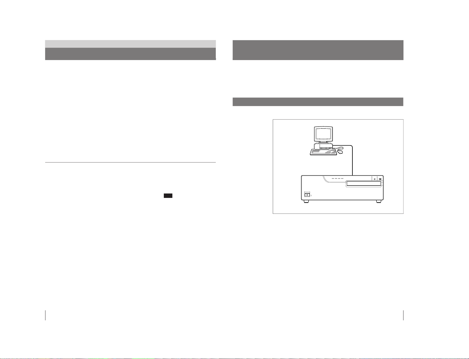
System Overview ..............................................................5
System Configuration....................................................... 5
Precautions........................................................................6
Safety................................................................................ 6
Installation........................................................................ 6
Cleaning ........................................................................... 7
Location and Function of Parts and Controls ................8
Front ................................................................................. 8
Rear .................................................................................. 9
Preparation
Supplied Accessories.....................................................10
Assembly........................................................................ 11
Setting the DIP Switch ....................................................12
Connecting the Computer ..............................................13
Operation
Before Printing ................................................................15
Loading an Ink Ribbon Cartridge .................................. 15
Loading the Paper .......................................................... 18
Printing.............................................................................20
Others
Ink Ribbon Cartridge and Paper ....................................22
Specifications..................................................................23
Troubleshooting..............................................................24
Indicators on the Front Panel ......................................... 25
If the Paper Jams ............................................................ 26

1-3
UP-D2550S (UC,CE)
4
Introduction
About This Manual
Introduction
This manual is divided into four chapters. This section explains the organization of
this manual.
Introduction
Describes the features and system configuration of the digital color printer. Notes
the precautions to be observed when using the printer. Also provided is
information on the location and function of parts.
Preparation
Explains the steps involved in setting up the printer prior to getting started—
checking the supplied accessories, assembly and connections.
Operation
Describes loading of the ink ribbon cassette and print paper and actual printing
operation.
Others
Provides technical information on the printer, how to handle error occurrence, and
how to deal with paper jams.
Conventions used
Cross reference
Throughout this manual you will find the references to other sections of the manual
that contain related information.
Important note
Be sure to read the sections of the manual marked Note . They explain points that
you should be aware of to operate the printer correctly and prevent malfunctions.
Trademarks
Windows is the trademark of Microsoft Corporation, USA.
Macintosh is the trademark of Apple Computer, Inc., USA.
Note
5
Introduction
The Sony UP-D2550S digital color printer is designed to reproduce computer
images on A6-size paper.
You can print out image data of Windows or Macintosh graphics application
software in high resolution (310dpi) and 256 shades of gray or in full color
(16,700,000 colors).
System Configuration
The following shows an example printer system configuration.
About the printer driver
The printer driver application program is stored in a file supplied with the CD-
ROM. For detailed information on how to install it, refer to the ReadMe file on the
CD-ROM.
System Overview
Digital color printer
Computer
Controls the printer operation.

1-4 UP-D2550S (UC,CE)
6
Introduction
Precautions
Safety
• Operate the printer using the power source specified in “Specifications” (page
23)
• Be careful not to damage the power cable by placing or dropping heavy objects
on it; it is dangerous to use the unit with a damaged power cable.
• If you do not intend to use the unit for a long time, disconnect the power cable.
• Unplug the power cable by grasping the plug, not the cable itself.
• Do not disassemble the unit.
• Do not remove the cover. There is a danger of electric shock from the internal
parts.
• Be careful not to spill water or other liquids on the unit, or to allow combustible
or metallic material to enter the cabinet. If used with foreign matter in the
cabinet, the unit is liable to fail, or present a risk of fire or electric shock.
• Ventilation holes are provided to prevent the unit from overheating. Be careful
not to obstruct them with other units or by covering the unit with a cloth etc.
• If the unit malfunctions or if a foreign body falls into the cabinet, disconnect the
power immediately and consult your Sony service facility or your Sony dealer.
Installation
• Avoid placing the unit in a location subject to:
— mechanical vibration
— high humidity
— excessive dust
— direct or excessive sunlight
— extremely high or low temperatures
• Do not use other electronic equipment near the unit. The unit will not work
properly in strong electromagnetic fields.
• Do not place a heavy object such as a monitor on the printer.
Condensation • If the printer is subject to wide and sudden changes in temperature, such as when
it is moved from a cold room to a warm room or when it is left in a room with a
heater that tends to produce large amounts of moisture, condensation may form
inside the printer. In such cases the printer will probably not work properly, and
may even develop a fault if you persist in using it. If condensation forms, turn off
the power and leave the printer to stand for at least one hour.
• If the printing pack is subjected to wide and sudden changes in temperature,
condensation may form on the ink ribbon or paper. This will cause the printer to
malfunction. Also, if the printing pack is used in this state, spots are likely to
appear on the printout. Therefore, avoid storing the printing pack in locations
subject to wide and sudden changes of temperature.
• To store a half-used printing pack, replace it in its original packing and reseal the
package. If possible, keep the sealed printing pack in a cool, dark location. To
subsequently use the printing pack, place it, in its sealed package, in a warm
room for several hours. Doing so prevents condensation from forming when the
printing pack is removed from its package.
7
Introduction
Location
To prevent internal heat built-up, leave enough room around the printer for air to
circulate through the vents on the left hand side of the cabinet.
On transportation
Do not transport the printer with the supplied accessories. Doing so may cause
malfunction.
Cleaning
Clean the cabinet, panel and controls with a soft dry cloth, or a soft cloth lightly
moistened with a mild detergent solution. Do not use any type of solvent, such as
alcohol or benzine, which may damage the finish.

1-5
UP-D2550S (UC,CE)
8
Introduction
Location and Function of Parts and Controls
For details, refer to the pages given in parentheses.
Front
1POWER switch (20)
Press to switch the unit on or off. The POWER
lamp lights green when the power is on.
2Top cover
Do not open this top cover. Only for service
personnel.
3PRINT indicator (20, 25)
Lights while printing.
Blinks while the printer is receiving data.
4ALARM indicator(20, 25)
Lights in case of paper jamming or occurrence
of any other problem.
5RIBBON indicator (20, 25)
Lights when a problem for ink ribbon
cartridge occurs.
6PAPER indicator (20, 25)
Lights when a problem for paper occurs.
The printer allows you to check the printer
operating condition according to the lighting
conditions of the PRINT indicator, ALARM
indicator, PAPER indicator and RIBBON
indicator.
For details, see “Indicators on the Front Panel”
on page 25.
9
Introduction
1SCSI connector (Half pitch 50-pin) (13)
Used to connect a computer, or another
peripheral, through an SCSI cable. The other
connector is loop-through connector for
another SCSI device. If either of the two
connectors is not being used, set the terminator
of the DIP switch to ON.
(see “Setting the DIP Switch” on page 12)
2SCSI ID DIP switch (13)
Used to set the SCSI ID number and the built-
in terminator to ON or OFF.
(see “Setting the DIP Switch” on page 12)
3Equipotential ground terminal 1
Used to connect to the equipotential plug to
bring the various parts of a system to the same
potential.
Refer to “Important safeguards/notices for use
in the medical environment” on page 2.
4⁄AC IN connector (13)
Used to connect the printer to a wall outlet
with the supplied power cord.
Rear
ab
c
7Front panel
Pull the top on the front door toward you to
open it.
Opening the front panel reveals the ink ribbon
cartridge, paper tray and paper cover.
When the front panel is open
aInk ribbon cartridge (11, 15)
Insert the ink ribbon cartridge.
bPaper cover (11)
Paper is ejected onto this cover.
cPaper tray (11, 18)
Load paper into this tray.
8STOP button (21)
Press to stop printing midway.
9PRINT button (20)
Press to print the image stored in the memory
of the printer again.

1-6 UP-D2550S (UC,CE)
10
Preparation
Preparation
Supplied Accessories
The printer is packed together with the following accessories. Check that nothing is
missing from your package.
Paper cover (1)
PUSH
Paper tray (1)
Notes
• Retain the original carton and packing materials in case you have to transport the
unit in the future.
• Remove the ink ribbon cartridge and paper tray when transporting the printer.
AC power cord (1)
Color printing pack (1)
a)
CD-ROM (1)
Roller Cleaning kit (1)
Software licence agreement (1)
User Registration card (1)
Warranty card (1)
Instructions for Use (1)
a) Use the ink ribbon cartridge and paper for operation check.
11
Preparation
Assembly
Attach the supplied paper cover, paper tray and ink ribbon cartridge to the printer.
For details of how to assemble them, see the pages given in parentheses.
Ink ribbon cartridge
(page 15)
Paper tray (page 18)
Paper cover
Printer
PUSH

1-7
UP-D2550S (UC,CE)
12
Preparation
Terminator SCSI ID
The DIP switches on the rear panel determine the on/off state of the internal SCSI
bus terminator and SCSI device ID number.
Terminator ON/OFF setting
If the printer is located at the physical end of the SCSI bus, this switch should be
set to ON. Otherwise, if another device is at the end of the bus, this switch should
be OFF.
Switch ON OFF
Terminator The internal terminator is ON. The internal terminator is OFF.
SCSI ID setting
The SCSI ID selection must be different from any other device on the bus. If two
SCSI ID devices have the same ID, a malfunction will occur.
SCSI ID SCSI ID switch
421
0 000
1 001
2 020
3 021
4 400
5 401
6 420
7 421
Setting the DIP Switch
OFF
ON
421
1
0
13
Preparation
to wall outlet
to⁄AC IN
Computer
to SCSI connector
a)
SCSI ID DIP switch
a)
AC power cord (supplied)
a) If the printer is located at the physical end of the SCSI bus, this switch should
be set to ON. (see “Setting the DIP Switch” on page 12)
Connecting the Computer
The UP-D2550S connects to the computer that supports the SCSI interface.
Before connecting the computer, see “Important safeguards/notices for use in the
medical environment” on page 2.
Notes
• Turn off the power of each device before attempting to make any connections.
• Grab the connector at the end of the connecting cable, and firmly insert it into the
socket.
• Before connecting the SCSI cable, make sure to turn off the power switches on
your computer and any peripheral equipment.
• The total length of the SCSI cabling used with a single-host computer should be
less than 6 meters.
• The length of the SCSI cabling used with a single-host computer should be less
than 1 meters.
SCSI cable
(not supplied)

1-8 UP-D2550S (UC,CE)
14
Preparation
Note
• SCSI cable connection requirement can vary between different computers and
peripherals. For the details of your installation, refer to the manual of your
computer and peripherals.
• Be sure not to connect the external terminator to the SCSI connector when the
terminator switch of the DIP switches is set to ON.
Turning on the power
You should turn on all peripheral devices before turning on your computers.
Particularly, make sure that all SCSI peripheral are turned on first.
Connecting the Computer (continued)
15
Operation
Operation
Before Printing
This section describes the following operations that must be made prior to starting
printing after mounting the paper tray and paper cover on the printer and making
the necessary connections.
• Loading an ink ribbon cartridge (see the below)
• Loading paper (see page 18)
Once the above operations have been completed, there should be no need to repeat
them during routine printing. Perform them only when absolutely necessary.
Loading an Ink Ribbon Cartridge
To make printouts, an ink ribbon cartridge and paper (which are compatible) must
be loaded. (see “Ink Ribbon Cartridge and Paper” page 22)
Use the ink ribbon cartridge and print paper (supplied) to check if the printer
functions properly.
Notes
• Use only ink ribbon cartridge and paper that are designed for use with this
printer. Failing to do so is likely to result in unsatisfactory printing or
malfunctions.
• When you replace the ink ribbon cartridge while you are operating the printer, do
not turn off the printer power. Turning off the power will cause the image stored
in the memory to be lost.
1
Open the front panel by pulling the front panel top toward you.
Continue to next page
m

1-9
UP-D2550S (UC,CE)
16
Operation
Before Printing (continued)
Note
Never put your hand into the ink ribbon compartment. The thermal head
becomes very hot. You may burn yourself if you touch it.
When the ink ribbon cartridge cannot be ejected
Turn the power off, then back on again. Then, after a while, press the ink ribbon
cartridge.
3
Remove any slack from the ink ribbon.
If the ribbon is left slack, it may be damaged when inserted.
Wind the spool until the not-used
point comes to the right end.
2
Remove the ink ribbon cartridge by pushing the ink ribbon cartridge itself.
The ink ribbon cartridge pops out.
When you use the printer first, this operation is not required.
17
Operation
Turn the spool in the direction of the
arrow to remove any slack until the
transparent tape cannot be seen.
Notes
When using ink ribbon cartridge
• Once an ink ribbon cartridge has been completely used, replace it. Ink ribbon
cartridges are not reusable.
• Do not touch the ink ribbon cartridge or place it in a dusty location. Finger prints
or dust on the ink ribbon will result in imperfect printing or malfunction of the
head.
When storing ink ribbon cartridge
• Avoid placing the ink ribbon in a location subject to:
— high temperatures
— high humidity
— excessive dust
— direct sunlight
• Store a partially used ink ribbon cartridge in its original packaging.
If your ink ribbon should tear
Repair the tear with transparent tape. There should be no problem with using the
remaining portion of the ribbon.
Transparent tape
4
Insert the ink ribbon cartridge firmly until it stops.
When the ink ribbon cartridge cannot be inserted
Turn the power off, then back on gain. Then, insert the ink ribbon holder.
5
Close the front panel.

1-10 UP-D2550S (UC,CE)
18
Operation
Before Printing (continued)
Loading the Paper
To load paper, follow the procedure below. Be careful not to touch the printing
surface.
Notes
• Use only ink ribbon cartridge and paper that are designed for use with this
printer. Failing to do so is likely to result in unsatisfactory printing or
malfunctions.
• When you load paper while you are operating the printer, do not turn off the
printer power. Turning off the power will cause the image stored in memory to
be lost.
1
Open the front panel by pulling the front panel top towards you.
2
Push the part marked with PUSH on the paper tray.
The paper tray pops out.
When you use the printer first, this operation is not required.
3
Place the paper in the paper tray.
Notes
• The amount of paper that the paper tray holds depends on the paper in use.
When adding paper to a partly full tray, be careful that the total number of
sheets does not exceed the limit. If you exceed this limit, paper jams may
occur.
The limit is the amount of paper contained in one printing pack.
For detailed information on the maximum amount of paper that the paper tray
can hold, see “Ink Ribbon Cartridge and Paper” page 22.
• Do not place different types of paper in the tray. Doing so may cause paper
jams to occur.
• Load the paper so that it lays flat in the paper tray. If the paper is curled, it
will overflow from the paper tray and the printing position may shift. If this
happens, load fewer sheets in the paper tray.
19
Operation
Front
Place the paper in the paper tray
with the printing surface facing up
Set the paper securely under
the tab.
Riffle the paper
4
Slide the paper tray back into the printer until it clicks into place.
5
Close the front panel.
Notes
When handling the paper
Do not touch the printing surface. Dust or finger prints are likely to cause
unsatisfactory printing or malfunction of the head. Hold the paper by the printing
surface protection sheet.
When storing print paper
• Avoid storing the print paper in a location subject to:
— high temperatures
— high humidity
— excessive dust
— direct sunlight
• Use the original package for storing unused paper.
Printing surface
PUSH

1-11
UP-D2550S (UC,CE)
20
Operation
Before printing
• Ensure that the printer is properly connected to the computer (page 13).
• Ensure that the correct ink ribbon cartridge and paper are used (page 22).
• Ensure that the ink ribbon cartridge and print paper are properly loaded (pages 15
and 18 ).
1
Turn on the power of the printer, then computer.
All indicators, PRINT, ALARM, RIBBON and PAPER are lit, then all of them
go out. Now the printer is in standby status.
Notes
• When the printer is connected to the computer through SCSI interface bus,
turn on the power of the printer before turning on the computer.
• Never turn the printer on or off while the computer is accessing its hard disk,
floppy disk.
2
Turn on the power of the computer.
3
Send the image data from the computer to the printer, then send the print
command.
While the printer is receiving the image data from the computer, the PRINT
indicator blinks.
While the printer is printing, the PRINT indicator is lit.
Printing
PRINT indicaton
ALARM indicaton
PAPER indicaton
RIBBON indicaton PRINT button
1
STOP
button
21
Operation
Notes
• Do not turn off the power during printing. If you do so, paper may not be ejected
and may jam in the printer.
• Do not pull the paper out till the printer finishes printing.
• Do not leave the printouts more than 10 sheets on the paper cover. Doing so may
cause jamming.
To stop printing midway
Send the command or press the STOP button to stop printing.
The printer returns to standby status.
If the printer does not print
The printer will fail to print in the following cases when the ALARM, PAPER,
and/or RIBBON indicator light.
For details, see “Indicators on the Front Panel” page 25.
When using the Self-laminating Color Printing Pack UPC-2040A
When the thermal head is cool, such as when making a first printout after switching
on the printer, the printer preheats the head until it is sufficiently hot to start
printing.
The print lamp blinks slowly during preheating. The printer automatically starts
printing when the thermal head is sufficiently heated.
Notes
When storing your printouts:
• Avoid storing the printout in a location subject to high temperatures, high
humidity, excessive dust and direct sunlight.
• Do not stick tape on a printout. Also, avoid leaving a plastic eraser on a printout
or placing a printout in contact with materials which contain plasticizer (under a
desk mat, for example).
• Do not allow alcohol or other volatile organic solvents to come into contact with
the printouts.

1-12 UP-D2550S (UC,CE)
22
Others
Ink Ribbon Cartridge and Paper
Both paper and an ink ribbon cartridge are necessary for printing. Use the ink
ribbon with the paper contained in the same package.
Color Printing Pack UPC-2010
Contains color ink ribbon cartridge and paper.
Color ink ribbon cartridge 1 roll
A-6 (4
1
⁄
4
×5
3
⁄
4
inches) size paper 200 sheets
Self-laminating Color Printing Pack UPC-2040A
Contains an ink ribbon cartridge and paper for automatic laminate coating.
Color ink ribbon cartridge 1 roll
A-6 size paper 120 sheets (The size is a little larger than paper of another printing
pack).
Self-adhesive Color Printing Pack UPC-20S01
Contains an ink ribbon cartridge and paper for sticker.
Color ink ribbon cartridge 1 roll
A-6 (4
1
⁄
4
×5
3
⁄
4
inches) size paper 200 sheets
16-split Self-adhesive Pre-cut Color printing pack UPC-20S16
Contains an ink ribbon cartridge and paper for sticker of 16 reduced images.
Color ink ribbon cartridge 1 roll
A-6 (4
1
⁄
4
×5
3
⁄
4
inches) size paper 200 sheets
4-split Self-adhesive Pre-cut Color printing pack UPC-20S04
Contains an ink ribbon cartridge and paper for sticker of 4 reduced images.
Color ink ribbon cartridge 1 roll
A-6 (4
1
⁄
4
×5
3
⁄
4
inches) size paper 200 sheets
Color Postcard Printing Pack UPC-2070E
Contains an ink ribbon cartridge and paper for post cards
Color ink ribbon cartridge 1 roll
A-6 size paper 150 sheets (The size is a little larger than paper of another printing
pack).
B/W Printing Pack UPC-2020
Contains an ink ribbon cartridge and paper.
B & W ink ribbon cartridge 1 roll
A-6 (4
1
⁄
4
×5
3
⁄
4
inches) size paper 200 sheets
Notes
• Use only the ink ribbon cartridge and paper designed for use with this printer. If
you use a different type, the printer may not print properly or malfunction.
• Use the ink ribbon with the paper contained in the same package. If the printer
detects an incompatible combination, ALARM and RIBBON indicators are lit.
Doing so may result in degradation of the print picture quality and occurrence of
any trouble.
• Ink ribbon and paper are not reusable. Once exhausted, replace them with new
ones.
About UPA-2002 paper tray (not supplied)
The paper size of the UPC-2040A self-laminating color printing pack and the
UPC-2070E postcard color printing pack is a little larger than paper of other
printing packs. The paper tray supplied with the printer is too small to load
UPC-2040A and UPC-2070E paper.
To use these types of paper, the UPA-2002 paper tray (not supplied) is required.
Others
23
Others
Specifications
Power requirements
120 V AC, 220 to 240 V AC, 50/60 Hz
Power consumption
About 1.0 A max. at 25°C, 240 V AC
About 1.8 A max. at 25°C, 120 V AC
Operating temperature
5°C to 35°C (41°F to 95°F)
Operating humidity
20 % to 80 % (no condensation allowed)
Storage and transport temperature
–20°C to 60°C (–4°F to 140°F)
Storage and transport humidity
20 % to 90 % (no condensation allowed)
Dimensions
About 370 ×125 ×417 mm (w/h/d)
(14
5
⁄
8
×5 ×16
3
⁄
4
inches)
Mass About 9.5 kg (20 lb 15 oz)
Printing system
Sublimation heat transfer printing
Picture Memory
4 Mbytes
Picture element
Maximum 1365 ×1024 dots (310 dpi)
Thermal head
12.2 dots/mm (1024 dots)
Total gradation
256 levels each for yellow, magenta, and
cyan
Digital interface
SCSI 1 channel
Half-pitch 50-pin connector ×2
Input: Max. 5 V DC
Output: Max. 5 V DC
Printing time
Approximately 50 seconds
(for color printing, excluding the data
transmission time)
Approximately 100 seconds
(for Self-laminating color printing,
excluding the data transmission time)
Protection against electric shock:
Class I
Protection against harmful ingress of water:
Ordinary
Degree of safety in the presence of flammable
anesthetics or oxygen:
Not suitable for use in the presence of
flammable anesthetics or oxygen
Mode of operation:
Continuous
Supplied accessories
Paper tray (1)
AC power cord (1)
Paper cover (1)
Color printing pack (1)
CD-ROMa) (1)
Roller Cleaning Kit (1)
Software license agreement (1)
User Registration card (1)
Warranty card (1)
Instructions For Use (1)
a) Contains data for the instruction
manual for the printer driver
Optional accessories
Color printing pack UPC-2010
Self-laminating color printing pack
UPC-2040A
Self-adhesive color printing pack
UPC-20S01
16-split Self-adhesive Pre-cut color
printing pack UPC-20S16
4-split Self-adhesive Pre-cut color
printing pack UPC-20S04
Color Postcard printing pack
UPC-2070E
B/W printing pack UPC-2020
UPA-2001 paper ejector
UPA-2002 paper tray
Design and specifications are subject to change
without notice.

1-13
UP-D2550S (UC,CE)
24
Others
Troubleshooting
The following troubleshooting check will help you correct the most common
problems you may encounter with your unit. Before proceeding with these trouble
checks, first check that the power cord is firmly connected. Should the problem
persist, unplug the unit and contact your sony service facility or your Sony dealer.
Symptom
The printer does not print even
if the command is sent from the
computer.
The printer does not print.
Possible causes and remedies
•The POWER switch of the printer is not set to ON.
nSet the POWER switch of the printer to ON.
•Connection may not be correct.
nCheck connections and rectify, if necessary.
•SCSI ID setting is not set correctly.
nCheck the SCSI ID setting. (page 12)
The problem is indicated by the indicators on the front panel.
nSee “Indicators on the Front Panel” on page 25 and perform
the proper remedies.
25
Others
Indicators on the Front Panel
If a problem occurs, the indicators on the front panel such as PRINT, ALARM,
RIBBON and/or PAPER light or blink to indicate the problem condition.
The following table show the relation between lighting or blinking condition of
each indicator and possible cause and remedies.
Indicators
Lighting
PRINT
PRINT
RIBBON
PAPER
ALARM and PAPER
ALARM and RIBBON
ALARM
PRINT, ALARM,
PAPER and RIBBON
a) The indicator blinks slowly.
Blinking
PRINT
PRINT
a)
ALARM
Possible cause and remedies
Printing
Data receiving
Adjusting the temperature of the thermal head so that the printer is
ready to print.
•Printing stops midway.
nThe indicators stop lighting and blinking after the paper is ejected.
•The paper which cannot be used, with this printer has been loaded.
nWait until the paper is ejected. Then, load the appropriate paper.
•The ribbon has been exhausted.
nReplace the old ink ribbon cartridge with the new one. The ink
ribbon cannot be reused. (page 15)
•The ink ribbon cartridge is not loaded.
nLoad the ink ribbon cartridge. (page 15)
•The paper has been exhausted.
nLoad the paper in the paper tray. (page 18)
•The paper tray is not installed.
nInstall the paper tray.
The ink ribbon cartridge and paper are not compatible.
nUse a valid combination of paper and ink ribbon cartridge. (page 22)
•The ink ribbon cartridge is defective.
nReplace the defective ink ribbon cartridge with the new one.
(page 15)
•The ink ribbon has torn.
nRepair the tear. (page 17)
•The ink ribbon cartridge that cannot be used with the printer.
nLoad the appropriate ink ribbon cartridge. (page 22)
The paper has jammed inside the printer.
nRemove the jammed paper. (page 26)
•Serviceman-call trouble occurs.
nTurn off the power immediately and contact your Sony service
facility or your Sony dealer.

1-14 UP-D2550S (UC,CE)
26
Others
Troubleshooting (continued)
If the Paper Jams
If the paper jams after starting printing, the ALARM indicator lights.
Follow the steps below to remove the jammed paper.
When the jammed paper is removed, you do not need to continue operation
explained below. Stop operation and reset removed paper cover, paper tray or ink
ribbon holder if any.
1
Open the front panel.
2
If any printouts have been ejected to the paper cover and have accumulated on
the paper cover, remove them. If not go to the next step.
3
Turn off the power of the printer.
4
Remove the paper cover.
When you can see paper inside the printer, go to step 5.
When you cannot see paper, go to step 8.
5
Slowly pull the paper into the paper tray.
Note
Never attempt to pull a jammed paper down, up, backwards, or forwards, the
paper may tangle or tear.
If you cannot pull the paper, go to step 8.
6
Remove the paper tray.
Printouts
Paper
27
Others
8
Remove the ink ribbon cartridge.
If there is a jammed paper, slowly pull out the paper.
If the ink ribbon cartridge cannot be removed, the printer must not be
operated. Contact your Sony service facility.
9
Re-insert the removed paper tray, paper cover or ink ribbon cartridge if you
removed, then close the front panel.
10
Turn on the power of the printer.
When the ALARM indicaton does not light, you can use the printer as normal.
If the ALARM indicaton lights again, the printer must not be operated. Turn
off the power immediately and contact your Sony service facility.
Note
If a paper jam occurs, the paper roller in the printer may be dirty. It is
recommended that you clean the paper roller once a month using the supplied
Roller Cleaning kit to keep it clean.
7
Load the paper into the paper tray correctly.
Do not reuse the paper put back in step 5. Discard that paper.
Set the paper securely
under the tab
Table of contents
Other Sony Printer manuals

Sony
Sony DPP-FP50 Fall 2005 User manual

Sony
Sony UP-897MD User manual

Sony
Sony UPX-C100 User manual

Sony
Sony DPP-SV55 User manual

Sony
Sony UP-D55 User manual

Sony
Sony DPP-FP97 User manual

Sony
Sony DPP-M55 Marketing User manual

Sony
Sony DPP-FP75 User manual

Sony
Sony DPP-FPHD1 Instruction Manual (Photo Printer) User manual

Sony
Sony UP-970AD User manual

Sony
Sony DPP-FP50 Fall 2005 User manual

Sony
Sony UP-D75 User manual

Sony
Sony DPP--SV77 User manual

Sony
Sony UP-CX2 User manual

Sony
Sony DPP-MS300 Marketing User manual

Sony
Sony DPP FP70 - Picture Station Photo Printer User manual

Sony
Sony Digital Photo Printer DPP-EX7 User manual

Sony
Sony UP55MD User manual

Sony
Sony UP-D897 User manual

Sony
Sony UP-5500 User manual