6Introduction
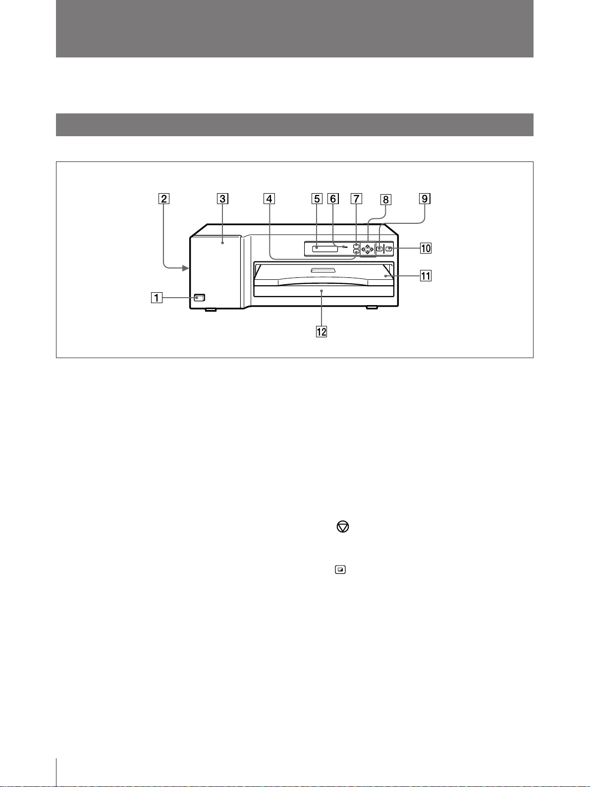
7MENU button (13, 23, 25)
Press this button to display or close the
printout adjust menu, gray balance adjust
menu and SCSI device type setting menu in
the printer window display.
8Cursor control buttons (13, 22, 23, 25)
Use these buttons to increase or decrease a
value and level shown on the menu, or scroll
up and down through a menu.
9STOP button (20)
Press this button to stop printing part-way.
0PRINT button (19, 20, 22)
Press this button to print the image data
stored in the memory of the printer.
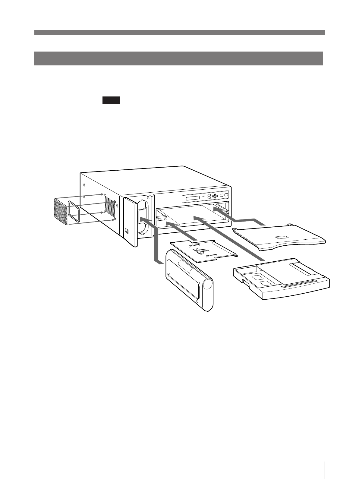
!¡ Paper cover (9)
Printouts are ejected here.
!™ Paper tray (9)
Load print paper here. Press the point
marked with PUSH to remove the paper
tray.
Location and Function of Parts and Controls
For details, refer to the pages indicated in parentheses.
Front
1UPOWER switch
Press to turn the printer on or off.
2Fan cover (9, 28)
Provided to prevent the printer from dust.
3Ribbon door (14)
Pull the tab (marked with PULL) on the top
on the ribbon door to open it when loading an
ink ribbon cassette.
4PRINT QTY (quantity) button (22)
Press this button to display or close the print
quantity setting menu in the printer window
display.
5Printer window display
Displays the status messages. In menu
operation, the print quantity setting menu,
printout adjust menu or gray balance adjust
menu is displayed.
Also, SCSI device type is dipslayed.
If an error occurs, a corresponding error
message is displayed.
6ALARM indicator (32)
Lights in orange when the ink ribbon or print
paper is exhausted, the paper jams, or another
problem occurs.