Table
of
Contents
Manual
Structure
Purpose
of
this
Manal
.........ccsscsscsssssecsceetsssessecesnsncateacseceesesseanes
3
Related
rian
als
sis;
ssseiecescscisceessoeedscerdsscstucosdensensscseccessasencsessseseseess
3
1.
Service
Overview
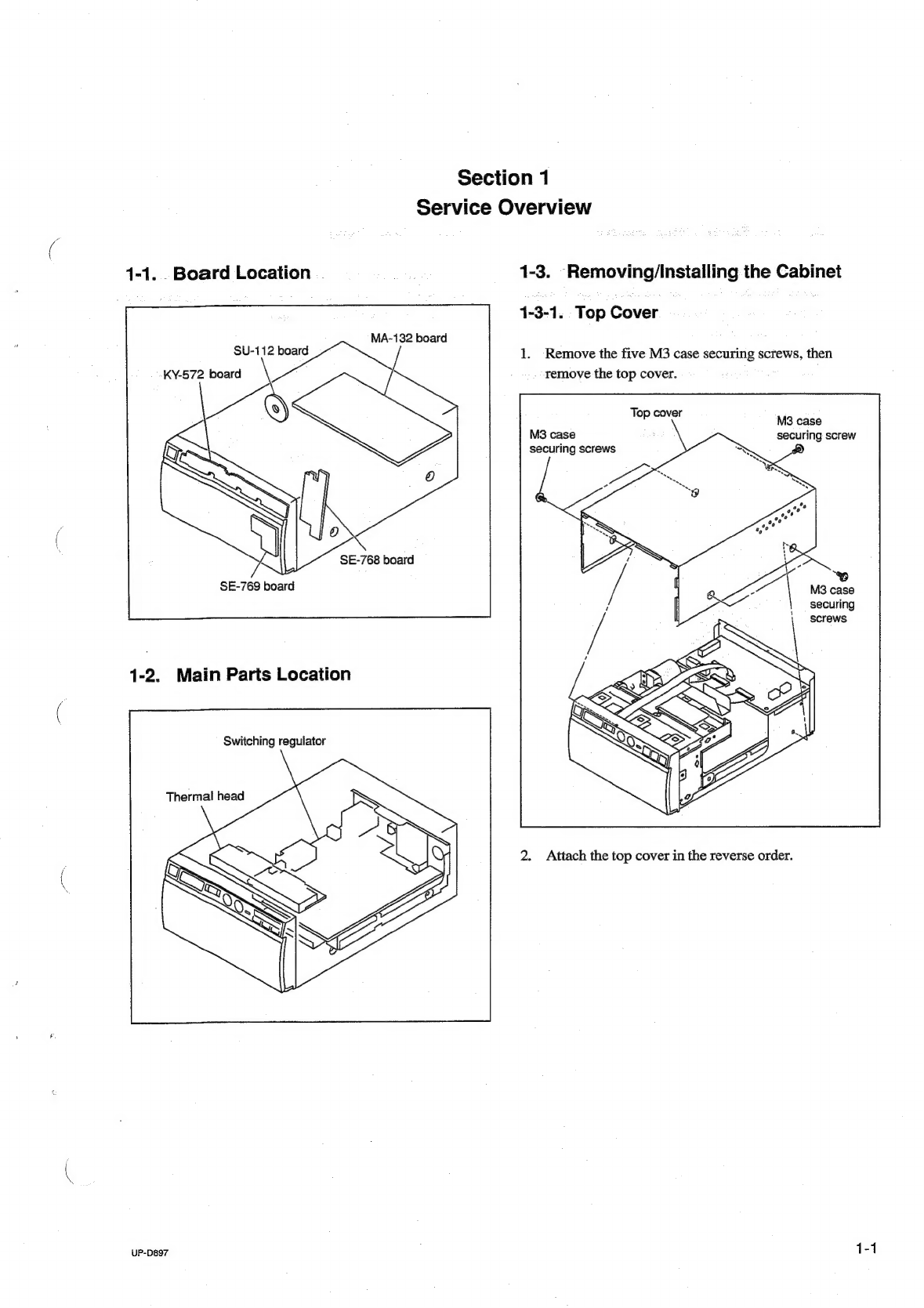
1-1.
Board
Location
1-1
1-2.
Main
Parts
Location
.........cccccssssssscssssssssssccsseserscecersesesce
1-1
1-3.
Removing/Installing
the
Cabinet
«0.0...
eeeseceesssseeees
1-1
1-3-1.
TLOD
COVER
ss
casds
ccavacsecsetssctlecestestvedeatecbsucssvesevenedecedscs
1-1
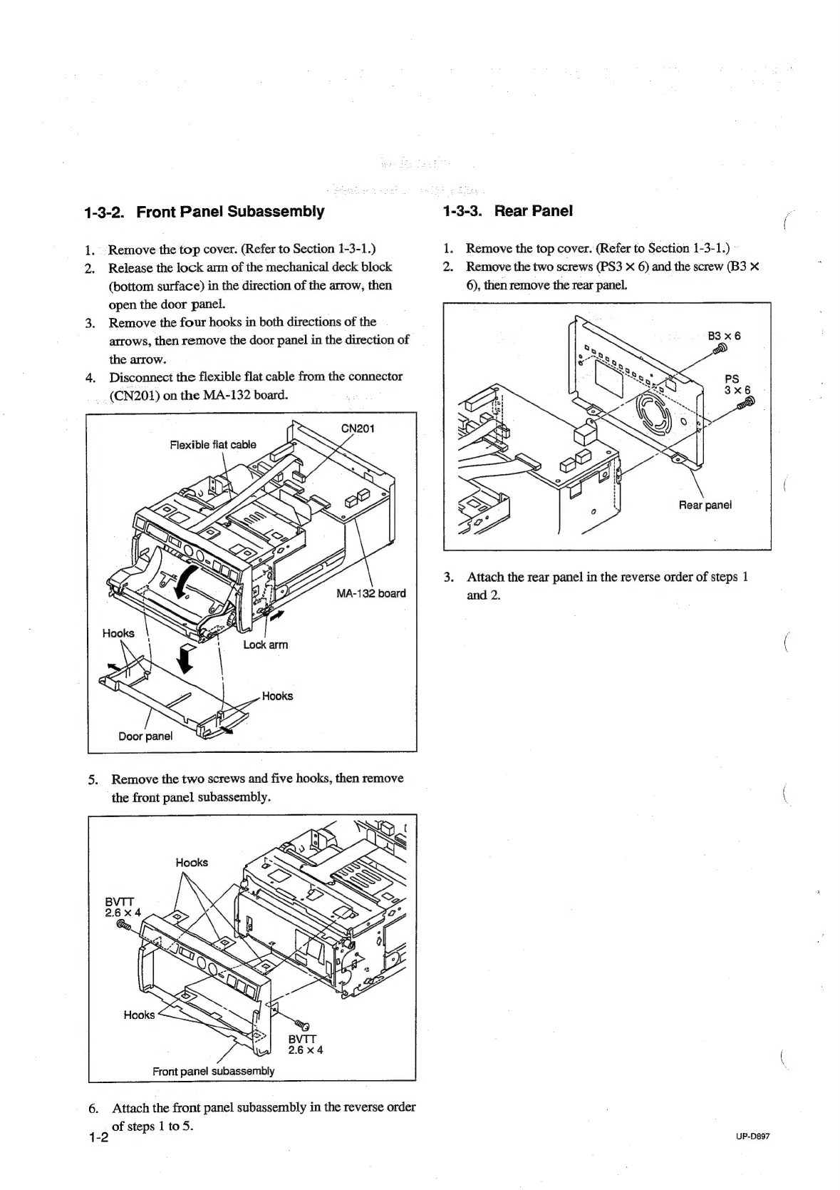
1-3-2.
Front
Panel
Subassembly
....
1-3-3.
Rear
Pane)
\ssigicciscssssinsssecssencsssncssecancscutcssacastaesosten
1-4,
Replacing
the
Main
Parts
........sccsssscscceeessecesstseesenceeeses
1-4-1.
Switching
Regulator/DC
Fan
........csssssssescsesveessee
1-3
1-4-2.
Mechanical
Deck
Assembly
............scccssssesseessessones
1-3
1-4-3.
Thermal
Head
.0.......sessssssssssesersssscrsscnseensseseseneeses
1-4
1-4-4,
Stepping
Motor/DC
Motor
.......c.cccssssssceesseseeseesere
1-5
1-4-5,
Cam
Shaft
Assembly
.............sessscsssscecseserssssessesseee
1-6
1-4-6.
Pinch
Arm
Assembly
.........scsccssssssssssssscsssererseesenes
1-7
1-4-7.
Platen
Roller
1-4-8.
Timing
Belt
....
1-5.
Procedure
Required
for
Replacement
............sssssesessesees
1-9
1-6.
Unleaded
Solder...
escsssesssssesssescsssssesessscsentessceseeness
1-9
2.
Electrical
Alignment
2-1.
Procedure
before
and
after
Adjustment
........sssssssesseseesee
2-1
2-1-1.
Procedure
of
Printing
the
User
Setting
Record
(Before
Adjustment)
...........cccessessessrsnsceseersreesseses
2-1
2-1-2.
User
Setting
Check
Procedure
(After
Adjustment)
........eecssccsesessssssecersereseesessees
2-1
2-1-3.
Factory
Setting
........sscccsssscssesssrescerssssceetssscssscernece
2-1
2-2.
Calibration
and
Electrical
Conductivity
Check
..............
2-2
2-3.
Head
Voltage
Adjustment
.........sscsscesccsescsscrsssssesssseceose
2-4.
Initialization
of
Print
Count
History
.
2-5.
Firmware
Version
Upgrade
......sscscssssccscessssesesssesssecacee
3.
Circuit
Description
3-1.
System
Control
BIOCK
........ccccssssssessccssrsecssessssseseesecseecsens
3-1
UP-D897
3-1-1.
Outline
«0...
ccescsessessceseeeesnstesassecsaetecssaseassetseenseesesees
3-1-2.
Block
Diagram
of
Electrical
Block
3-2.
Head/Mechanical
Control
Block
3-2-1.
OUTLINE
sisacissdecdensasavccssssesccniancnedsssnoasiaaisuseatedesdinesea
3-2-2.
Platen
Motor
Control...
a
3-2-3.
Thermal
Head
UP/DOWN
Control
3-2-4.
Monitoring
of
Door
Sensor
oi...
cesesssssescsseessseenees
3-2
3-2-5.
Monitoring
of
Paper
Sensor
...
3-2
3-2-6.
Monitoring
of
Head
Temperature
Sensor..............
3-2
3-2-7.
Control
of
Head
Fan
Motor
(for
Head
Cooling)
...3-2°
3-2-8.
Read
of
Buttons
3-3
3-3°-
USB
Unter
faces.
écissecccncsvscgascasen
chsdvesugetsassaecosseselussarsessbyenss
3-3
3-4.
Thermal
Head
BIOCK
...........scscssssesssesssccessecersseneresseceesneres
3-3
3-4-1.
GS
PUCUUN
x.
oc
soseecatlaces
depeden
satel
esiciasiiccssetucsnanestcueies
3-3
3-4-2.
Basic
Operation
...........
+0
3-3
3-4-3.
Temperature
Correction
.......cssssessseesseseserseseseeneees
3-4
3-4-4,
Correction
of
Resistor
COount.........scccseecesseereeeees
3-4
4.
Troubleshooting
4-1.
Print
result
is
not
SatisfactOry
.......scsssccecssessssscesersesseeres
4-1
4-2.
Print
result
density
is
too
high
or
LOW
.......seesssesesseoseees
4-1
43.
Trouble
of
determining
presence
or
absence
of
paper
....4-2
4-4.
Thermal
head
UP/DOWN
operation
trouble
.............006
4-2
4-5.
Feed
operation
trouble
..........ssscsesssssseeeescecsseneseeeeesensees
4-6.
Trouble
of
determining
door
open/close
5.
Service
Mode
(Self-diagnosis
Function)
5-1.
Startp
Procedure
..........essssssscsssvsscceecssesnssssersetenesseonees
5-1
5-2.
Service
Mode
Men
..........sssccssssssssessesssecetenssaceeteeesarsenenes
5-1
5-3.
Test
Pattern
Printing
...........scssscsccsesssaseesssesserssesneesseseees
5-1
5-4.
Test
Pattern
Print
Count
.......ssssscssssssssesressesssstseesesseerees
5-3
5-5.
LCD
Lighting
Check
5-6.
LED
Lighting
Check
5-7.
Front
Panel
Volume
Calibration
...........csessssssssecosserseses
5-4
5-8.
Log
Printing
...........sssssssseseceseesssesecsssssssnterseseenetestensneesons
5-4
5-9.
Initialization
of
Setting
..........cssssseccesssssssrscscesserssceseneee
5-5