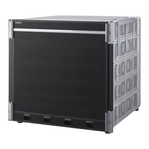
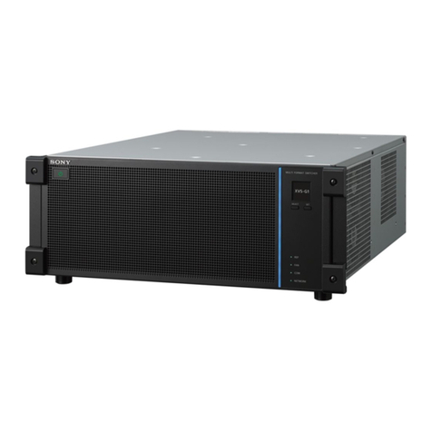
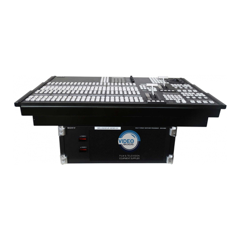
Sony BRS-200 Quick start guide

BRS-200
Operational Manual
sony.com/ptz
click: sony.com/sonysports
SONY56230_BRS-200.indd 1 4/28/10 1:43:32 PM

Table of Contents
1 What is the BRS-200?
1-1) Main features.............................................................................................................4
1-2) Applications...............................................................................................................5
2 Overview
2-1) Control panel.............................................................................................................6
2-2) Rear panel of the processor unit..............................................................................8
3 Main Features
3-1) Compact system .....................................................................................................10
3-2) Remote camera control capability ........................................................................10
3-3) Switcher mode and camera control mode...........................................................11
3-4) Rich selection of inputs and outputs......................................................................12
3-5) Equipped with DVI output as standard..................................................................13
3-6) Multi-viewing function .............................................................................................14
4 Specifications 15
5 System Examples
5-1) Basic configuration..................................................................................................16
5-2) For live production...................................................................................................16
5-3) For presentation.......................................................................................................17
5-4) For presentation with dual projectors.....................................................................17
6 Basic Setup and Operation
6-1) Turning on the power ..............................................................................................18
6-2) Menu operation.......................................................................................................20
6-3) Setting the system format........................................................................................22
6-4) Setting up video signal for monitor output ............................................................23
6-5) Setting up the VISCA camera .................................................................................24
7 Preparation
7-1) Setting up video input signal..................................................................................25
7-2) Setting up video output signal ...............................................................................27

8 Switcher Operation
8-1) Outline......................................................................................................................29
8-2) Cut/Mix ....................................................................................................................31
8-3) Wipe .........................................................................................................................32
8-4) Picture-in-Picture (PIP)..............................................................................................36
8-5) DSK............................................................................................................................41
8-6) Internal Sources .......................................................................................................48
8-7) Storing Settings ........................................................................................................50
9 VISCA Camera Operation
9-1) Functions..................................................................................................................52
9-2) Setting up BRC Series camera connection............................................................53
9-3) Operating pan/tilt/zoom ........................................................................................54
9-4) Adjusting the focus..................................................................................................55
9-5) Adjusting the exposure ...........................................................................................56
9-6) Selecting One-push Auto White Balance...............................................................57
9-7) Using the camera position preset ..........................................................................58
9-8) Operating the camera menu.................................................................................61
9-9) Controlling the tally lamp........................................................................................61
10 Operation Using External Device
10-1) Transferring data between the BRS-200 and computer ........................................62
10-2) Specifications for a GPI I/O connector ..................................................................67
10-3) Using the REMOTE Connector.................................................................................68
11 Technical Appendix
11-1) Menu list ...................................................................................................................69
11-2) WIPE pattern.............................................................................................................80
11-3) GPI I/O......................................................................................................................81
11-4) REMOTE connector ..................................................................................................82
11-5) VISCA Connector.....................................................................................................83
11-6) Connector for the cable between Control Panel and Processor Unit..................83
11-7) Conversion between input signal and output signal ...........................................84
11-8) Acceptable DVI-I Input/Output Signal format.......................................................86
11-9)
Camera Settings that Can Be Recalled with the Position Numbers of the Switcher
.......87
11-10) Messages and Troubleshooting..............................................................................88
11-11) Dimensions...............................................................................................................89

4
1What is the BRS-200?
The BRS-200 is an all-in-one live production and presentation switcher with BRC
Series control functionality.With this powerful tool, you can achieve a one-man
production operation in either HD or SD system configuration.
Compact control
panel and 1U
processor unit
HD/SD-SDI 4 inputs/
4 outputs, max.
9 inputs/5 outputs*
Built-in frame
synchronizer on
each input
Picture in Picture
function, DSK,
and Wipe
BRC Series camera
control capability
Equipped with DVI
output as standard
Multi-viewing function,
supporting
4-, 10-, or 16-split view
2 channels of frame
memory
1-1) Main features
*A maximum of 9 inputs and 5 outputs of HD/SD-SDI is available using optional boards.

5
What is the BRS-200?
Auditorium/Concert Hall City Council
Corporate/Boardroom Education
House of Worship
Sports Event
Weddings/Events
Studio
1-2) Applications

6
2Overview
2-1) Control panel
1456
32

NEAR FAR
EXIT
PAG E
FOCUS BRIGHT ZOOM PAN/TILT
F1 F2 F3 F4
CAMERA
MENU
LEFT
X
ENTER
Y
DOWN
CENTER
UP
FINE
RIGHT
Z
7
DSK PIP SETUP
MEM
MENU/SNAP SHOT/CAMERA POSITION
WIPE MATT
89
MENU
456
DIRECT
RECALL
123
PRESET
0.
CLEAR RECALL
N/R
DSK
AUTO
PIP
AUTO
AUTO
TRANS
CUT
REV
MX
WIPE
CAMERA
DSK
DEEPSTESERPHGIHWOL
P/T RST
PIP
PST SPD
AUX 1
AUTO/MANUAL
AUX 2
O P AF
PGM
BK LIGHT
PVW
SPT LIGHT
MV
O P AWB
CAMERA
DSK/AUX 123456789101112
CAM
SW
SETUP
INPUT
NAME..
FS..
ASSIGH..
SIDE..
ADJUST.. 1/1
920
PROC..
SETUP
INPUT
NAME..
FS..
ASSIGH..
SIDE..
ADJUST.. 1/1
920
PROC..
Display panel
Adjustment controls
EXIT button
PAGE button
Higher menu layer
Current displayed menu layer
Lower menu layer
Menu page
Page number
CAMERA MENU button
Camera menu
operation buttons/
location control buttons
MENU button
DIRECT RECALL button
PRESET button
RECALL button
CLEAR button
Numeric (0 to 9) buttons and
. (dot) button
Transition
lever
Transition
indicator
PIP AUTO button
DSK AUTO button
REV button
MIX button
WIPE button
AUTO TRANS button
CUT button
N/R button
CAM (camera) mode button
SW (switcher) mode button
CAMERA buttons / DSK/AUX buttons
One Push AF button /
AUX 2 button
One Push
AWB button /
MV button
SPT LIGHT button /
PVW button
Backlight button /
PGM button
AUTO/MANUAL button /
AUX 1 button
P/T Reset button /
DSK button
Preset Speed button /
PIP button
7
Overview
1. Mode button
(Camera mode/Switcher
mode select)
2. CAMERA/DSK/AUX bus section
3. Effect transition section 4. Menu/snapshot/camera position
section
5. Display panel/Camera/Switcher/
Menu control section
6. Camera menu/Location control
selection buttons

8
Overview
2-2) Rear panel of the processor unit

9
Overview
1
IN1
234PGM1 PGM2 AUX1
SDI OUTSDI IN
AUX2 GPI I/O PANEL
IN2 OUT
SDI IN1 to 4 connectors
PGM1/PGM2 output connectors
AUX1/AUX2 output connectors
GPI I/O connector
PANEL connector
REF IN REF OUT RS-232C
~AC IN
RS-422
DVI-I OUT
GENLOCK VISCA
LAN(10/100) REMOTE
DVI-I OUT connector
(ground) terminal
~ AC INconnector
LAN(10/100) connector
REMOTE connector
REF INconnector
REF OUT connector
RS-232C connector
RS-422 connector

10
3Main Features
t &BTZBOEGMFYJCMFTFUVQ
t $POTVNFTNJOJNBMTQBDFGPSDPNGPSUBCMFPQFSBUJPO
t /POFFEUPXPSSZBCPVUDPNQMJDBUFEDBCMFDPOOFDUJPOT
t $POUSPMVQUPTFWFO#3$4FSJFTDBNFSBTWJB34$PS347*4$"
t &OKPZUIFTBNFDBNFSBDPOUSPMGVODUJPOBMJUZWJBUIF3.#3SFNPUF
control unit
t 4USFBNMJOFZPVSQSPEVDUJPODSFXTFWFOBPOFNBOPQFSBUJPOJTQPTTJCMF
BRC-H700 BRC-Z700 BRC-Z330 BRC-300
1 unit 2 units (BRS-200)
3-1) Compact system
3-2) Remote camera control capability

11
Main Features
CAM mode: Position presets, Recall
SW mode: Snapshot presets, Recall
CAM mode: Camera menu selection
SW mode: P in P position selection
CAM mode: Camera selection
SW mode: DSK/AUX bus selection
CAM mode: PTZ control
SW mode: P in P position/Size selection
PGM/NEXT bus control
+
3-3) Switcher mode and camera control mode
Note: PGM/NEXT bus control can be operated both in CAM mode and SW mode.

12
Main Features
t &JHIU4%*BOEPOF%7**JOQVUNBYJNVN
t 'PVS4%*BOEUXP%7**PVUQVUNBYJNVN
t #VJMUJOGSBNFTZODISPOJ[FSPOFBDIJOQVU
Optional boards
Card slot
IN1 IN2 OUT
HD/SD-SDI input board
BRSA-20HSD1 Yes No No
DVI input board
BRSA-20DD1 Yes Yes No
Analog SD input board
BRSA-20SA1 Yes Yes No
DVI output board
BRSA-20DD2 No No Yes
Combinations of inputs and outputs
Input
Standard Option
Standard Option
SDI-I
SDI x4SDI x4
SDI x4
SDI x4
SDI x4
SDI x4
SD (Composite, Y/C)
or
DVI-I DVI-I
DVI-I
DVI-I DVI-I
SD (Composite, Y/C) SD (Composite, Y/C)
SD (Composite, Y/C)
++
++
++
++
++
1
IN1
234PGM1 PGM2 AUX1
SDI OUTSDI IN
AUX2 REF IN REF OUT RS-232C
~AC IN
RS-422
DVI-I OUT
GENLOCK VISCA
GPI I/O PANEL LAN(10/100) REMOTE
IN2 OUT
IN 1 card slot IN 2 card slot OUT card slot
Optional boards and card slots
Output
3-4) Rich selection of inputs and outputs

13
Main Features
t 4VQQPSUT869(")%5749("89("BOE9("JO)%NPEFBOE49("89("
and XGA in SD mode
t *O)%57NPEFBJBOBMPHDPNQPOFOUTJHOBMJTPVUQVU5IJTBMMPXT
operators to view footage on a cost-effective HDTV monitor or PC monitor with
an analog component terminal
DVI
DVI to D-Sub
Connector
BNC or
PIN(RCA)
D-Sub
WUXGA, SXGA,WXGA, XGA mode
HDTV mode
DVI
DVI DVI IN
RGB INPC Monitor
HD Monitor
Component IN
D-Sub
REF IN REF OUT RS-232C
~
AC IN
RS-422
DVI-I OUT
GENLOCK VISCA
REMOTE
3-5) Equipped with DVI output as standard
DVI-I Connection

14
Main Features
t "TJOHMFNPOJUPSDBOEJTQMBZBMMJOQVUTJHOBMT1(.BOE178WJB4%*BOEPS
DVI-I outputs
t &BTZUPEFUFSNJOFXIJDITJHOBMJTPOUIFBJSBOEXIJDIJTUPCFQSFTFOUFE
t 6TFSTDBODIPPTFGSPNTJOHMFTDSFFONPEFPSTQMJUTDSFFONPEFXIJDIMFUT
VTFSNPOJUPSGPVSUFOPSTJYUFFOTDSFFOTTJNVMUBOFPVTMZ
TYPE1
TYPE4
TYPE10
TYPE16
1
34
78
2
56
910
12
56
910
13 14
34
78
11 12
15 16
PVW
IN 1 IN 2
IN 5 IN 6
PGM
IN 3 IN 4
IN 7 IN 8
PVW PGM
IN 1 IN 2
IN 5 IN 6
IN 9
FM 1 FM 2
IN 3 IN 4
IN 7 IN 8
MAT2MAT1 CLBR
1
12
43
PGM
PVW PGM
IN 2IN 1
Type of multi-viewer Picture number Factory preset output video
123456789101112
123456789101112
Type 1 (full-screen mode) is useful for checking the focus and also for taking a close look at
the subject.
T I P S
3-6) Multi-viewing function

15
4Specifications
BRS-200 HD Mode SD Mode
(FOFSBM 1PXFS3FRVJSFNFOUT "$ 7UP 7 )[
1PXFS$POTVNQUJPO 1SPDFTTPSVOJU 8XJUIPVUPQUJPOBMCPBSET 8XJUIPQUJPOBMCPBSET
Control panel: 15 W
Operating 41°F to 104°F (5°C to 40°C)
Temperature
Dimensions Processor unit: 17 × 13
/
4× 17 inches (430 × 44 × 430 mm) (without protrusions)
Control panel: 163
/
4× 2 7
/8× 8 3
/
4inches (424 × 70 × 222 mm) (without protrusions)
8FJHIU 1SPDFTTPSVOJU P[ LHXJUIPVUPQUJPOBMCPBSET P[ LH
(with optional boards)
Control panel: 9 oz (4.3 kg)
7JEFP'PSNBUT )%JJ 4%JJ
4JHOBM1SPDFTTJOH :$C$SCJU
2VBOUJ[BUJPO :CJUT$CJUT,&:CJUT
I/O Delay 1H (When the frame synchronizer is OFF)
*NBHF &GGFDU 5SBOTJUJPO$65.*9'BEFS"6508*1&'BEFS"650
Effect P in P (AUTO)
%4, $ISPNBLFZ-VNJOBODFLFZ-JOFBSLFZ4QMJU
Input Video Inputs*1 HD-SDI: BNC (×4) SD-SDI: BNC (×4)
Video Inputs HD-SDI: BNC (×4) SD-SDI: BNC (×4)
(option)*1*2 %7**¨49("89("9("
"OBMPHDPNQPTJUF#/$¨4WJEFPQJONJOJ%*/¨*3
3FGFSFODF*OQVU "OBMPHCMBDLCVSTUPS "OBMPHCMBDLCVSTU#/$¨
5SJMFWFMTZOD#/$¨XJUI XJUI-PPQUISPVHI#/$¨
-PPQUISPVHI#/$¨
0VUQVU 7JEFP0VUQVU )%4%*1(.¨"69¨#/$ 4%4%*1(.¨"69¨#/$
4JHOBMT %7**¨869(")%57*449("89("9(" %7**¨49("89("9("
7JEFP0VUQVU %7**¨869(")%57*449("89("9(" %7**¨49("89("9("
(option)
Reference Output Analog black burst or Tri-level sync.: BNC (×1) Analog black burst: BNC (× 1)
Control Remote RS-422: D-sub 9-pin (×1) (for switcher control from external devices)
Signals (1*5"--: 0VUQVUQPSUTTFMFDUBCMFGPS*0T%TVCQJO¨
VISCA camera VISCA RS-232C: Mini DIN 8-pin (×1)
control VISCA RS-422: 5-pin contact connector (×1) (for BRC Series camera control)
-"/ #"4&53+GPSUIFUSBOTGFSPGTUJMMJNBHFTTOBQTIPUEBUBBOEDBNFSB
preset positions)
*1: The BRS-200 does not accept the mix of HD-SDI and SD-SDI.
.BYJNVNPGGJWFJOQVUTDBOCFBEEFE$PNCJOBUJPOPGUXPJOQVUCPBSETPG#34")4%#34"4"
BOE#34"%%DBOCFJOTUBMMFEUPUIF#340OMZGPSUIF#34")4%TJOHMFCPBSEDBOCFJOTUBMMFE
to the BRS-200.)
*O)%NPEFJOQVUTJHOBMTDBOCFVQDPOWFSUFEUPVTFBT)%TJHOBMT
*O)%57NPEFJBOBMPHDPNQPOFOU:1C1SJTBWBJMBCMF

HD-SDI
HD-SDI
HD-SDI Card
HD-SDI Card
DVI
(MV)
HD-SDI
(PGM)
VISCA
HD-SDI
HD-SDI
HD-SDI Card
HD-SDI Card
SDI Adaptor
SDI Adaptor
DVI
(MV)
HD-SDI
(PGM)
HD-SDI
(PGM)
HD-SDI
(AUX1: PRV)
VISCA
16
5System Examples
5-1) Basic configuration
5-2) For live production

HD-SDI
HD-SDI
HD-SDI Card
HD-SDI Card
BRSA-20SA1
BRSA-20DD1
BRSA-20DD2 DVI
(PGM)
HD-SDI
(PGM)
DVI
(MV)
VISCA
Composite
or S-Video (1)
RGB ––> DVI
HD-SDI
HD-SDI
HD-SDI Card
HD-SDI Card
BRSA-20SA1
BRSA-20DD1
BRSA-20DD2
SDI Adaptor
DVI
(PGM)
HD-SDI
(PGM)
DVI
(DVI Source)
HD-SDI
(AUX1: MV)
VISCA
Composite
or S-Video (1)
RGB ––> DVI
17
System Examples
* SD analog source can be input in conjunction with HD-SDI source by using BRSA-20SA1.
* SD analog source can be input in conjunction with HD-SDI Source by using BRSA-20SA1.
5-3) For presentation
5-4) For presentation with dual projectors

18
6Basic Setup and Operation
"GUFSDPOOFDUJPOUVSOPOQPXFSPGUIFTZTUFNCZGPMMPXJOHUIFTFTUFQTCFMPX
1. Set the power switch on the front of the processor unit to ON.
2. Set the power switch at the rear of the control panel to ON.
3. Turn on power to the peripheral devices.
/PUFJGZPVIBWFDIBOHFEUIFGBDUPSZQSFTFUTFUUJOHTVTFi'"$54&5wPOUIFNFOVUPSFTFUUIF
TFUUJOHTUPEFGBVMU'PSEFUBJMTQMFBTFSFGFSUPUIF0QFSBUJPONBOVBM
Basic component of system configuration
t #34QSPDFTTPSVOJUBOEDPOUSPMQBOFMTFU
t 4POZ#3$4FSJFTXJUIBO)%4%*PVUQVUDBSEBUUBDIFEVOJUT
t .POJUPSFRVJQQFEXJUIBO)%4%*JOQVUPS%7*JOQVUVOJU
6-1) Turning on the power
This section explains how to perform basic system setup.

19
Basic Setup and Operation
System connection
Note: Please be sure to turn off all the equipment before connection.
1234
PGM1 PGM2 AUX1
SDI OUTSDI IN
AUX2 REF IN REF OUT RS-232C
~
AC IN
RS-422
DVI-I OUT
GENLOCK VISCA
GPI I/O PANEL LAN(10/100) REMOTE
IN1 IN2 OUT
DC IN 12V OFF
ON
PROCESSOR
RS-232C
~
AC IN
RS-422
VISCA
RS-232C
~
AC IN
RS-422
VISCA
DC IN 12V
DC IN 12V
BRC-series cameras
with the HD-SDI
output card attached
Monitor equipped
with HD-SDI input
Monitor equipped
with DVI input
SDI OUTPUT
or
HD-SDI IN
Processor Unit
to PROCESSOR
to DC IN 12V
AC power adaptor
(supplied)
Power cord for AC
power adaptor
(supplied)
to an AC outlet
to an AC outlet
Control Panel
RS-232C IN
SDI OUTPUT
UP1"/&-
VISCA (RS-232C)
cable
to VISCA
RS-232C
Control cable
(supplied)
to ~AC
IN
AC power cord
(supplied)
to SDI
IN 1
to SDI
IN 2
Screws
+M3 × 6
(supplied)
DC IN plug retainer
(supplied)
VISCA
(RS-232C)
cable
Power cord
stopper
(supplied)
to AUX1 to DVI-I OUT
DVI IN
RS-232C
IN
RS-232C
OUT

20
Basic Setup and Operation
t5PEJTQMBZUIFNFOVOVNCFS
A 3 -digit menu page is assigned to each of all the setting menus displayed
in menu mode. Pressing the menu button specifies the menu directly. Press
UIFOVNFSJDCVUUPOTGPSiUIJSEEJHJUOVNCFSwiEPUwiTFDPOEEJHJUOVNCFSw
BOEiGJSTUEJHJUOVNCFSwJOTFRVFODF
Example:To select menu page 912
Every menu consists of three digit number. Please see technical appendix 11-1.
*OUIFGPMMPXJOHFYBNQMFUFYUUIFNFOVQBHFJTEFTDSJCFEBTGPS
FYBNQMF
t5PQNFOVMJTU
A list of menu items is shown.To
TFMFDUPOFPGUIFTFJUFNTQSFTTUIF
corresponding numeric button (4 to 9).
Each button lights up when pressed.
7
DSK PIP SETUP
MEM
MENU/SNAP SHOT/CAMERA POSITION
WIPE MATT
89
MENU
456
DIRECT
RECALL
123
PRESET
0.
CLEAR RECALL
Numeric buttons, . (dot) button
MENU button
9.12
MENU
MENU
912
Numeric
button
Top menu Menu description
4 MEM (memory)
menu
Importing an image into
the frame memory, Time
stamp setting for a file
5 WIPE menu Setting the wipe pattern
or border
6 MATT menu Setting the color matte
7 DSK menu Setting the DSK
(downstream key)
8 PIP menu Setting the PIP (picture-
in-picture)
9 SETUP menu Setting up the system
6-2) Menu operation
*GZPVXBOUUPLFFQUIFiUIJSEEJHJUOVNCFSwTJNQMZQSFTTiEPUwiTFDPOEEJHJUOVNCFSwBOE
iGJSTUEJHJUOVNCFSwJOTFRVFODF
T I P S
Other manuals for BRS-200
2
Table of contents
Other Sony Switch manuals

Sony
Sony ESBK-7052 User manual

Sony
Sony MVS-8000X SystemMVS-7000X System User manual

Sony
Sony DVS-9000 User manual

Sony
Sony MVS-6520 User manual

Sony
Sony HDS-7150 User manual

Sony
Sony DFS-700 User manual

Sony
Sony MKS-2010 User manual

Sony
Sony BVS-V3232 User manual

Sony
Sony DFS-700 User manual

Sony
Sony XVS-9000 User manual
Popular Switch manuals by other brands

Hewlett Packard Enterprise
Hewlett Packard Enterprise FlexFabric 5940 Series Configuration guide

JETI model
JETI model ENLINK 2RS Plus user manual

ORiNG
ORiNG GS-9164GF Series installation guide

Hewalex
Hewalex OPTI–HOME Installation and maintenance guide

ZGO Technologies
ZGO Technologies Zhub user guide

Konig
Konig CMP-EHUB52 manual